BIOMET OnPoint User manual
OnPoint™
Operation and Care Manual
1.2mm Scope System
Anticipate. Innovate.
TM
Manufactured by BioVision Technologies, LLC
Manufactured for

OnPoint™ Scope System
Table of Contents
1.0 Introduction
1.1 The OnPoint™ 1.2mm Scope System
1.2 Indications for Use
1.3 Contraindications
1.4 Regulatory Compliance
1.4.1 Electromagnetic Compatibility Chart
1.5 Warranty Information
1.6 How to Use This Manual
1.7 Manual Conventions
1.8 List of Symbols
2.0 Product Specifications
2.1 Contents
2.2 Features and Specifications
2.2.1 OnPoint™ Features
2.2.2 Technical Specifications
2.3 Safety Information
3.0 Setup and Basic Usage
3.1 Setup
3.1.1 OnPoint™ System
3.1.2 Attaching a Camera System and Endoscope(s)
3.1.3 Attaching External Video Devices
3.1.4 Attaching Virtual Reality Glasses
3.1.5 Setting Up and Operating MediaCaptureUSB
3.1.5a Still Capture Mode
3.1.5b Video Capture Mode
3.1.5c Reviewing Images
3.1.5.6 Set Up
3.1.5.7 Set Recording Time Limit
3.1.5.8 Set Clock Time & Date
3.1.5.9 Set Audio Setting
3.1.5.10 File System Manager
3.1.5.11 Format Media Ooption
3.1.5.12 OSD Overlay Position
3.1.5.13 Lamp Counter Notification
3.1.5.14 Video Playback Mode
1

Operation and Care Manual
2
IMPORTANT
The OnPoint™ 1.2mm Scope System is indicated to provide illumination
and visualization of anatomy in an interior cavity of the body through a
natural or surgical opening. This device is indicated for diagnostic and
operative arthroscopic and endoscopic procedures. The device is to be
used by a trained physician for the indicated uses only.
This manual describes the recommended procedures for preparing and
operating the OnPoint System. It does not describe how any medical
procedure is to be performed on a patient with this instrument.
Read all instructions in this manual carefully before using the OnPoint
1.2mm Scope System.
Carefully follow all safety instructions to prevent injury to the user or patient,
fire hazards, electrical shock, and damage to the device.
To maintain this device in optimal condition, follow all recommendations
in this manual for handling, cleaning, and storage.
Table of Contents
3.1.5.15 VGA Gamma Set Up
3.1.5.16 Print File Format
3.1.5.17 Capture Mode Set Up
3.1.5.18 Video Output Test
3.2 Basic Usage
3.2.1 Setup for Each Procedure
3.2.2 Power-Down Procedures
3.2.3 Single-use Endoscope Disposal
4.0 Cleaning and Maintenance
4.1 Cleaning of OnPoint™ System
4.2 Sterilization of OnPoint™
4.3 Lamp Life Monitoring and Replacement
4.4 Recommendations for the Disposal of the Device
4.5 Fuse Replacement
5.0 Troubleshooting

OnPoint™ Scope System
1.0 Introduction
Thank you for your purchase of the OnPoint™1.2mm Scope System. This piece
of equipment is designed and built to give you the latest technology and
the best performance. This manual will help you make the most of your
equipment investment.
1.1 The OnPoint™ 1.2mm Scope System
The OnPoint system combines several essential surgical requirements into
a single compact & portable package:
Xenon Fiber Optic Light Source
By employing state-of-the-art lamp power supply technology, a proprietary
xenon arc lamp incorporates an enhanced reflector and delivers near
175-watt illumination performance for outstanding image quality.
Proprietary High-Resolution Camera System
The OnPoint camera is a high-resolution 480-line digital camera. It uses a
quick-release optical connector that adapts to a wide variety of surgical
endoscopes. A proprietary single cable design eliminates the complexity
and cost of the traditional dual-cable system approach.
Integrated Video Display with Multiple Outputs
The OnPoint high-resolution 6.4” LCD monitor combines the performance
of the Xenon Fiber Optic Light Source and High Resolution Camera System
to deliver a brilliant, high-resolution video image for clear detail recognition
and outstanding color reproduction.
Multiple Output options on the OnPoint unit allow you to connect larger
external video monitors, video printers, and video recording devices.
MediaCaptureUSB
A full-featured, fully-integrated image capture system is included in every
OnPoint system. Every OnPoint has the capability to capture video, still
images, full-resolution video, and audio-tagged still images. Using the
popular CompactFlash® media format, MediaCaptureUSB enables users
to quickly and conveniently document their procedures. Connect directly
to a computer via USB and use the OnPoint to browse captured media
or capture still images and video directly to your practice management
software, running on Windows 2000 or Windows XP.
Camera System: CMAR-01
High-Resolution endoscopic/arthroscopic camera system with integrated
light cable and MediaCaptureUSB capture button.
3

1.2 Indications for Use
The OnPoint 1.2mm Scope System is indicated to be used by a trained
physician to provide illumination and visualization of an interior cavity of
the body through a natural or surgical opening in diagnostic and operative
arthroscopic and endoscopic procedures.
1.3 Contraindications
The OnPoint 1.2mm Scope System is contraindicated for use in applications
where high intensity light might damage tissue, such as neonate
transillumination and ophthalmic procedures. For other contraindications,
consult the literature accompanying the instrumentation utilized with this
device.
1.4 Regulatory Compliance
The OnPoint 1.2mm Scope System complies with all regulations to be
marketed in the United States of America, Canada, and the European Union.
This device complies with EN60601-1 and all collateral standards.
This device complies with part 15 of the FCC rules.
This device complies with the Medical Device Directive (Council Directive
93/42/EEC).
Federal law restricts this device to sale by or on order of a physician
licensed by the law of the state in which he practices to use or order the
use of this device.
Operation and Care Manual
4
OnPoint™ Scope System
1.4.1 Electromagnetic Compatibility (IEC 60601-1-2)
5
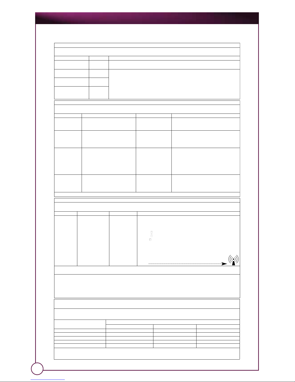
Guidance and Manufacturer’s Declaration- Electromagnetic Immunity
The OnPoint™is intended for use in the electromagnetic environment specified below. The customer or the user of the OnPoint™
should assure that it is used in such an environment.
Immunity Test IEC 60601 Test Level Compliance Level Electromagnetic Environment - Guidance
Conducted RF
IEC 61000-4-6
Radiated RF
IEC 61000-4-3
3 V rms
150 kHz to 80 MHz
outside of ISM bands
10Vrms
150 kHz to 80 MHz
in ISM bands
10 V/m
80 MHZ to 2.5 GHz
10 V rms
10 V/m
Portable and mobile RF communications equipment should be used no closer to any part
of the OnPoint™including cables, than the recommended separation distance calculated
from the equation applicable to the frequency of the transmitter.
Recommended separation distance
d= (3.5/3) P
d= (3.5/3) P 80 MHz to 800 MHZ
d= (7/3) P 800 MHz to 2.5 GHz
Where P is the maximum output power rating of the transmitter in watts (W) according to
the transmitter manufacturer and dis the recommended separation distance in meters
(m). Field strengths from fixed RF transmitters, as determined by an electromagnetic site
survey, ashould be less than the compliance level in each frequency range b.
Interference may occur in the vicinity of equipment marked with the following
symbol
NOTE 1 At 80 MHz and 800 MHz, the higher frequency range applies.
NOTE 2 These guidelines may not apply in all situations. Electromagnetic propagation is affected by absorption and reflection from structures, objects and people.
aField strengths from fixed transmitters, such as base stations for radio (cellular/cordless) telephones and land mobile radios, amateur radios, AM and FM radio
broadcast and TV broadcast cannot be predicted theoretically with accuracy. To assess the electromagnetic environment due to fixed RF transmitters, anelectro-
magnetic site survey should be considered. If the measured field strength in the location in which the Xe3000 is used exceeds the applicable RF compliance level
above, the OnPoint™should be observed to verify normal operation. If abnormal performance is observed, additional measures may be necessary, such as reori-
enting or relocating the OnPoint™.
bOver the frequency range 150 kHz to 80 MHz, field strengths should be less than 3 V/m
Guidance and Manufacturer’s Declaration- Electromagnetic Emissions
The OnPoint™is intended for use in the electromagnetic environment specified below. The customer or the user of the OnPoint™
should assure that it is used in such an environment.
Emissions Test Compliance Electromagnetic Environment - Guidance
RF Emissions
CISPR 11
Group 1 OnPoint™uses RF energy only for its internal function. Therefore, its RF emissions are very
low and are not likely to cause any interference in nearby electronic equipment.
RF Emissions
CISPR 11
Class B The OnPoint™is suitable for use in all establishments other than domestic and those directly
connected to the public low-voltage power supply network that supplies buildings used for
domestic purposes.
Harmonic Emissions
IEC 61000-3-2
Class A
Voltage Fluctuations /
Flicker Emissions
IEC 61000-3-3
Complies
Guidance and Manufacturer’s Declaration- Electromagnetic Immunity
The OnPoint™is intended for use in the electromagnetic environment specified below. The customer or the user of the OnPoint™
should assure that it is used in such an environment.
Immunity Test IEC 60601 Test Level Compliance Level Electromagnetic Environment - Guidance
Electrostatic
Discharge (ESD)
IEC 61000-4-2
+ 6 kV contact
+ 8 kV air
+ 6 kV contact
+ 8 kV air
Floors should be wood, concrete or ceramic tile.
If floors are covered with synthetic material, the
relative humidity should be at least 30%.
Electrical Fast
Transient/Burst
IEC 61000-4-4
+ 2 kV for power supply lines
+1 kV for input/output lines
+ 2 kV for power supply
lines
+1 kV for input/output
lines
Mains power quality should be that of a typical
commercial or hospital environment.
Voltage Dips, short
interruptions and
voltage variations
on power supply
input lines.
IEC 61000-4-11
<5% UT(>95% dip in UT for 0,5 cycle
40% UT (60% dip in UT) for 5 cycles
70% UT(30% dip in UT) for 25 cycles
<5% UT(>95% dip in UT) for 5 sec.
100% dip for 0.5 cycles
60% dip for 5 cycles
30% dip for 25 cycles
100% dip for 5 seconds
Mains power quality should be that of a typical
commercial of hospital environment. If the user
of the OnPoint™requires continued operation
during power mains interruptions, it is
recommended that the OnPoint™be powered
from an uninterruptible power supply or a battery.
Power Frequency
(50/60Hz) magnet-
ic field
IEC 61000-4-8
3 A/m 3 A/m Power frequency magnetic fields should be at
levels characteristic of a typical location in a
typical commercial or hospital environment.
NOTE: UT is the ac mains voltage prior to application of the test level.
Recommended separation distances between portable and mobile RF communications equipment
and the OnPoint
TM
The OnPoint™is intended for use in an electromagnetic environment in which radiated RF disturbances are controlled. The customer or the user of the OnPoint™
can help prevent electromagnetic interference by maintaining a minimum distance between portable and mobile RF communications equipment (transmitters) and
the OnPoint™as recommended below, according to the maximum output power of the communications equipment.
Rated maximum output power of
transmitter (W)
Separation distance according to frequency of transmitter
150kHz to 80MHz 80MHz to 800MHz 800MHz to 2.5GHz
0.01 0.035 0.035 0.07
0.1 0.11 0.11 0.22
1 0.35 0.35 0.7
10 1.12 1.12 2.21
100 3.5 3.5 7
For transmitters rated at a maximum output power not listed above, the recommended separation distance d in meters (m) can be estimated using the equation applica-
ble to the frequency of the transmitter, where P is the maximum output power rating of the transmitter in watts (W) according to the transmitter manufacturer.
NOTE 1 At 80 MHz and 800 MHz, the separation distance for the higher frequency range applies.
NOTE 2 These guidelines may not apply in all situations. Electromagnetic propagation is affected by absorption and reflection from structures, objects and people.

Operation and Care Manual
6
1.5 Warranty Information
When delivered to the end user in new condition in the original container,
the OnPoint 1.2mm Scope system is warranted to be free from defects in
material or workmanship for one year from the date of shipment from
Biomet Microfixation to the end user.
Within the above listed time periods, parts that are returned, freight prepaid,
to Biomet Microfixation and are determined by Biomet Microfixation to be
defective will be repaired or replaced by BioVision Technologies without
charge for parts, labor, or return ground shipping costs. Biomet Microfixation
will make every effort to accomplish this repair or replacement within a
reasonable time. After the warranty period, the purchaser must pay all
charges for repair and replacement. This warranty does not cover products
intended for single patient use beyond the initial use or consumable items.
The above actions by Biomet Microfixation shall constitute your exclusive
remedy and Biomet Microfixation’s sole obligation under this warranty.
Biomet Microfixation shall not be responsible for warranty claims made
after the warranty period. To obtain warranty repair service, you must
contact Biomet Microfixation to obtain a Return Material Authorization
(“RMA”) number, then return the product, freight prepaid, to Biomet
Microfixation. The RMA number and a complete explanation of the
problem must be included with the product being returned to Biomet
Microfixation for warranty service. The product to be repaired must be
returned in its original box and packaging, or a similar box and packaging
affording an equivalent degree of protection. Upon completion of repairs,
Biomet Microfixation will return the product to the end user, freight prepaid.
The warranty period for replacement parts shall begin upon shipment of
same, but shall in no event exceed the warranty period of the defective
part. Biomet Microfixation shall have no liability or obligation for a product
that has been subjected to any of the following:
Failure caused by or attributable to Acts of God, improper use, abuse,
negligent care or handling, accident, faulty installation, improper
cleaning, improper maintenance, or other indications of excess voltage.
This warranty is also void if the product has been repaired or modified
without prior written authorization from Biomet Microfixation, if the end-user
has failed to follow the instructions or heed the warnings or specifications
in the Operation and Care Manual, or if the product’s serial number has
been altered or removed.
EXCEPT FOR THE FOREGOING WARRANTIES, BIOMET MICROFIXATION HEREBY DISCLAIMS AND
EXCLUDES ALL OTHER WARRANTIES, EXPRESS OR IMPLIED, INCLUDING BUT NOT LIMITED TO
ANY AND/OR ALL IMPLIED WARRANTIES OF MERCHANTABILITY OR FITNESS FOR A PARTICULAR
PURPOSE. BIOMET MICROFIXATION HEREBY DISCLAIMS ANY REPRESENTATIONS OR WARRANTY
THAT THIS PRODUCT OR ANY OF ITS PARTS IS COMPATIBLE WITH NON-BIOMET MICROFIXATION
PRODUCTS OTHER THAN VIDEO EQUIPMENT ATTACHED TO ITS VIDEO OUTPUTS, AS DESCRIBED
IN THE OPERATOR’S MANUAL. THE LIABILITY OF BIOMET MICROFIXATION, IF ANY,

OnPoint™ Scope System
AND PURCHASER’S SOLE AND EXCLUSIVE REMEDY FOR DAMAGES FOR ANY CLAIM OF ANY KIND
WHATSOEVER, REGARDLESS OF THE LEGAL THEORY, SHALL NOT BE GREATER IN AMOUNT THAN
THE PURCHASE PRICE OF THE PRODUCT SOLD BY BIOVISION TECHNOLOGIES THAT CAUSED
ANY ALLEGED DAMAGE. IN NO EVENT SHALL BIOMET MICROFIXATION BE LIABLE TO PURCHASER
FOR ANY SPECIAL, INDIRECT, INCIDENTAL, OR CONSEQUENTIAL DAMAGES OF ANY KIND.
7
Contact Biomet Microfixation for warranty information
904.741.4400 • 800.874.7711
www.biometmicrofixation.com
Distributed by Biomet Microfixation
1.6 How to Use This Manual
The intention of this document is to convey the proper and prescribed
operation and care of the OnPoint™ 1.2mm Scope System.
1.7 Manual Conventions
This manual adheres to a set of conventions to help you easily find the
information you need and inform you of important information that will
help you efficiently and effectively use your equipment.
Sections and sub-sections are noted as follows:
Special and important information is called out using notes and warnings.
Notes usually pertain to a recommended protocol that will help extend
the life of your equipment. Warnings pertain to protocols that delineate
appropriate actions which maintain a safe and healthy work environment.
Notes and warnings are called out in the following manners:
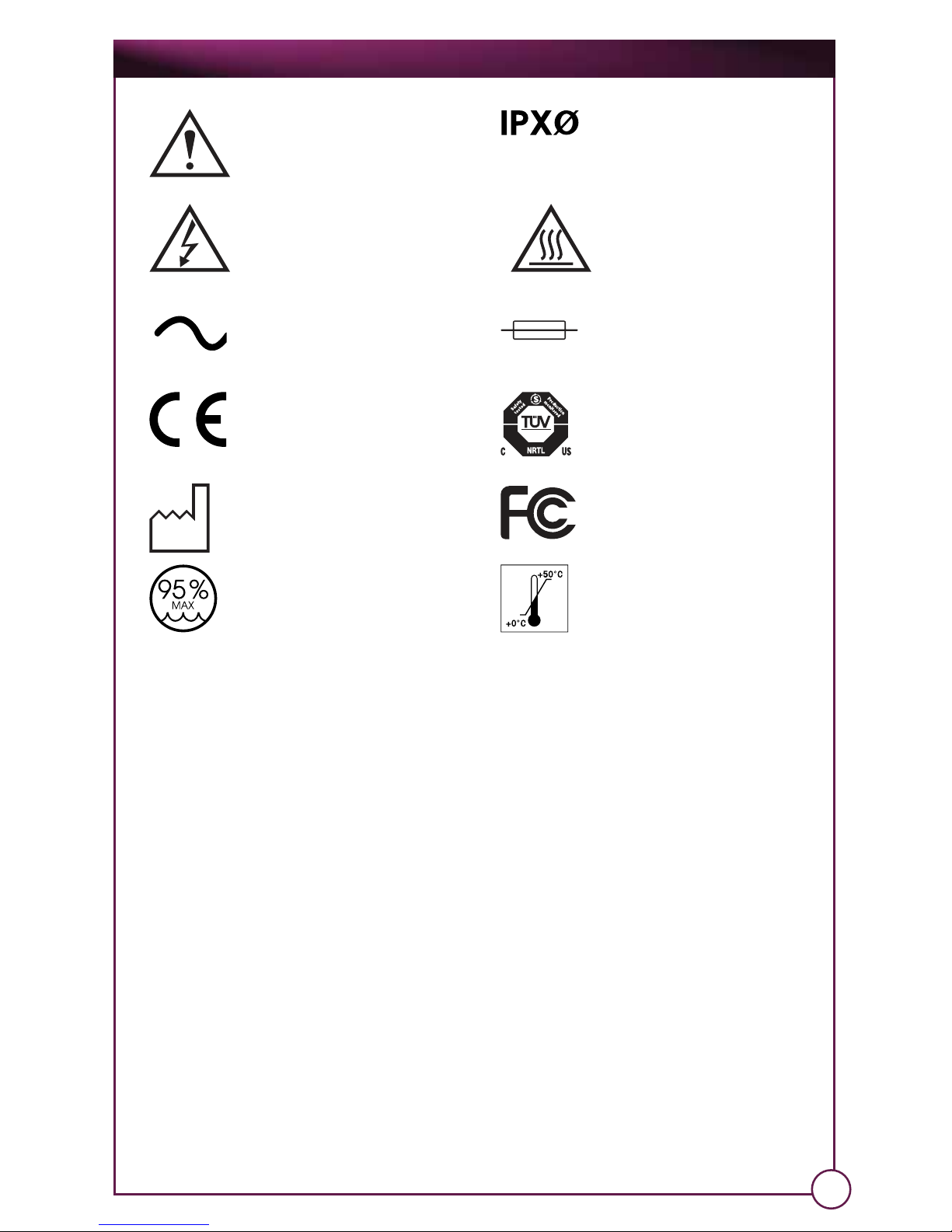
1.8 List of Symbols (used in this manual and product labels)
Note: This is a note.
WARNING: This is a warning.
1.0 Section Title
1.1 Sub-section title
Hazard Warning. Type BF
Applied Part
Operation and Care Manual
8
2.0 Product Specifications
The following section describes the components and features of the
OnPoint™ system.
2.1 Contents
The following components are included in your OnPoint system:
OnPoint™Integrated Visualization System (Base Unit)
Medical Grade Power Cord
Operation and Care Manual
Check to see that you have all of these components before proceeding.
If any of these components are missing, contact Biomet Microfixation
immediately using the contact information below:
Biomet Microfixation
1520 Tradeport Drive
Jacksonville, FL 32218-2480
Phone: 800.874.7711 or 904.741.4400
www.biometmicrofixation.com
Alternating Current Fuse
Storage Humidity Transport Temperature
European CE Mark
PRODUCT SERVICE
TUV, Nationally Recognized Testing
Laboratory (NRTL) Mark
Federal Communications
Commission Mark
Date of Manufacturing
Attention: Read Operating Manual
for Warnings, Precautions, and
Instructions for Use.
Caution - High Voltage Caution - Hot
Not Protected Against the
Ingress of Water
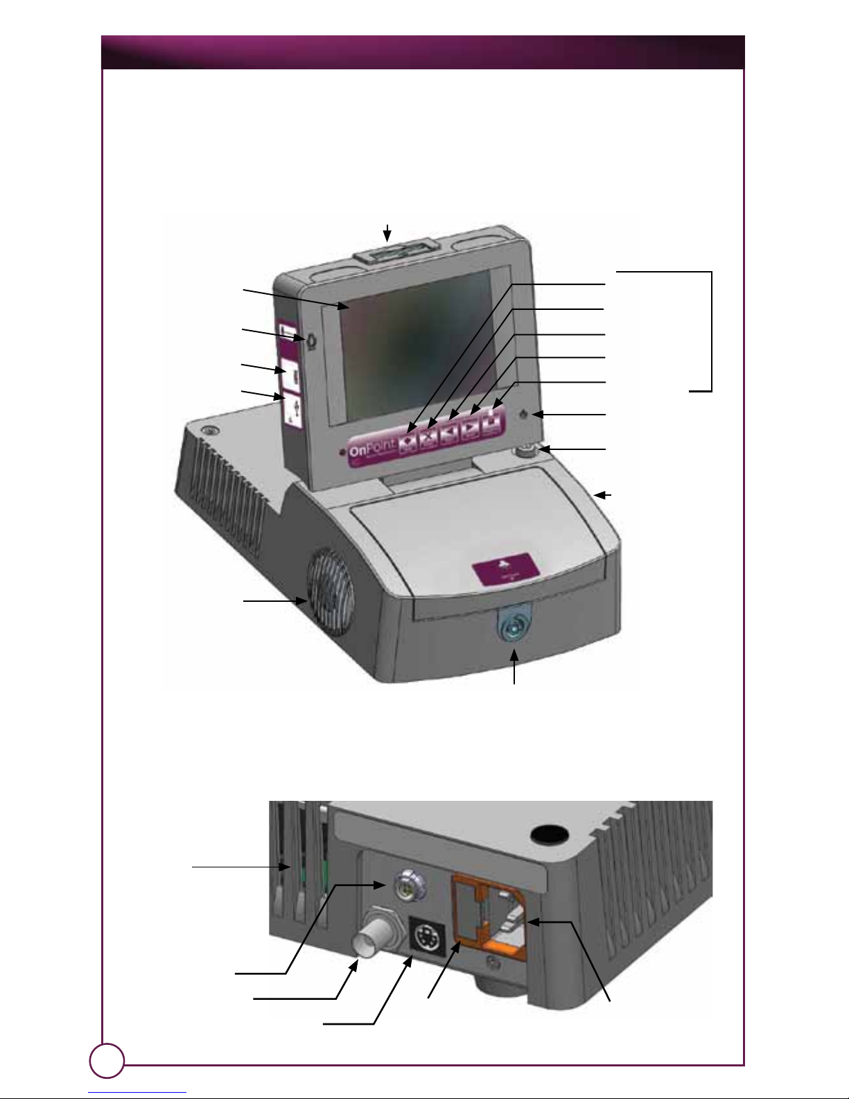
Rear
2.2 Features and Specifications
2.2.1 OnPoint Features
Microphone
PS2 Keyboard
Connection
USB Connection
Mode
Delete
Left Select
Right Select
Stop/Enter
Power Indicator
Power Button
Speaker
Ventilation
Exhaust
Integrated
LCD Monitor
CompactFlash® Media Slot
Camera Connector/Light port
S-Video
Ventilation
Exhaust
VR Connector
Composite Video Fuse Holder Power
Connector
KEYPAD
OnPoint™ Scope System
9
Operation and Care Manual
10
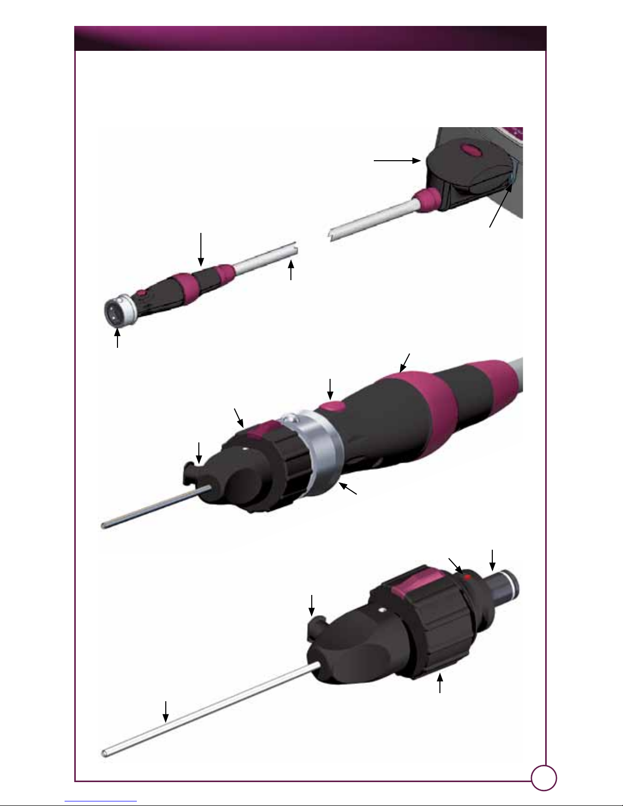
Handpiece
Camera POD
Camera
Handpiece
Camera
Connector
Scope
Coupler
Focus Knob
Image Capture
Button
Scope
Cannula
Sliding Sleeve
Scope Probe/Cannula
Cannula Luer Fitting
Coupler
Scope Handle
Scope
Fiber-optic cable
Alignment Dot
OnPoint™ Scope System
2.2.2 Technical Specifications
11
Electrical
Input voltage: 120/230VAC, 50/60Hz
Input current: 3.0/1.5A maximum.
Power connector: IEC 320
Classification: IEC60601-1 Class I, Type BF equipment
Mode of operation: Continuous
Fuse: 3.15A 250V Type F
Environmental
Operating altitude: -304.8 to 3657.6m(-1000 to 12000 ft) MSL.
Operating temperature: 0ºC to 40ºC (-32ºF to 104ºF).
Operating humidity: 0% to 95% RH, non-condensing.
Storage/transport altitude: -304.8 to 10668m (-1000 to 35000 ft) MSL.
Storage/transport temperature: 0ºC to 50ºC (-32ºF to 122ºF).
Storage/transport humidity: 0% to 95% RH, non-condensing.
Video / Display
Input video format: NTSC Composite, 75Ω, 1Vp-p.
Video output 1: NTSC Composite, 75Ω, BNC.
Video output 2: NTSC Y/C, 75Ω, 4-pin circular DIN.
Video output 3: NTSC Composite, 75Ω, 4-pin VR glasses
connector.
Display type: LCD 16.25 cm (6.4 in) TFT,
active matrix (960Hx 234V)
Light Source
Type: Xenon Arc
Lamp: BL35WXe
Power: 35W
MediaCaptureUSB
Storage media: CompactFlash®
Still image file format: JPEG
Still image size: 640x480 pixels.
Video file format: AVI (MJPEG codec)
Video size/fram rate: 640x480 pixels/30fps.
Compatible Camera Attachments
Needlescope: 24-3000
2.3 Safety Information
General requirements for the safe use of the device:
• It is important that you read, understand, and comply with all of the
following safety precautions, markings, labeling, and all accompanying
literature.
• Failure to follow these precautions could result in injury to the patient or
user, or damage to the OnPoint™ unit.
• When used in the presence of other energized, endoscopically-used
devices and accessories, such as Lasers and High Frequency Surgical
equipment, the safety precautions for such equipment must also be
followed.
Operation and Care Manual
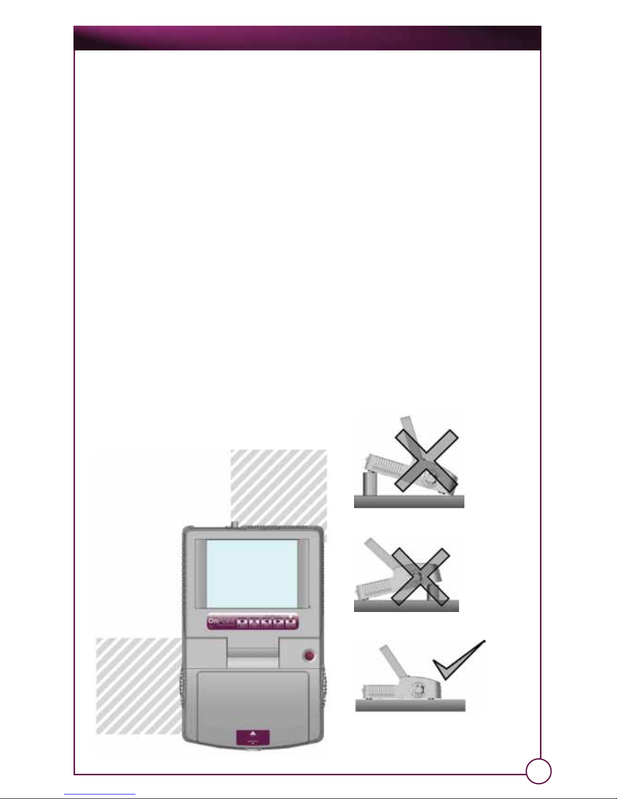
Sufficient clearance is
maintained by allowing
an area six inches by six
inches both behind and
on the left side of the
OnPoint™ unit.
• Before each use, check the outer surface of the arthroscope and
arthroscopic accessories to ensure there are no unintended rough surfaces,
sharp edges, or protrusions that may cause a safety hazard to the patient
or user; or cause damage to the equipment and other accessories.
• In the event of use with other surgical tools, such as shavers, care shall be
taken to avoid damage to the arthroscope or any arthroscopic
accessories. All damaged instruments shall be discarded immediately.
• In the event of a loss of system function during a procedure, no further
visualization is necessary, and the procedure is ended, the physician shall
remove the arthroscope and proceed with closure or further patient care
as needed. Further arthroscopic examination shall only be performed with
a fully functional system, for which a backup unit is recommended.
To avoid personal injury and damage to this device:
• Do not block ventilation slots or openings. Always ensure sufficient
clearance for ventilation by not placing any other equipment or objects
on or near the vents on either side of the OnPoint™ unit.
• Always place and keep the OnPoint unit on a flat, level, and secure
surface.
• In the event of suspected damage or failure, DO NOT OPERATE and have
the device inspected by qualified personnel.
12
A flat surface will provide the optimal
performance.
Ventilation
Clearance
6x6 inches
Ventilation
Clearance
6x6 inches

OnPoint™ Scope System
13
To avoid fire hazard and electrical shock:
• Do not operate the device outside of the specified input voltage range.
• Only use medical-grade power cords with the OnPoint™ system.
• Connect to a properly grounded hospital-grade outlet only.
• Use only the fuse type and rating specified for this device.
• DO NOT operate the OnPoint™ system in an explosive atmosphere (e.g. in the presence
of flammable anesthetics, etc.).
• The OnPoint™ unit does not have any field-replaceable parts. DO NOT disassemble or
open the front cover or any other covers or panels. Opening the front cover will void the
manufacturer’s warranty.
• Do not operate this product if there are signs of tampering or any of the covers are removed.
• Do not allow foreign objects inside of the device.
• Before performing any kind of maintenance (e.g. cleaning the OnPoint™ system,
replacing fuses, etc.), always perform the following:
Unplug the power cord.
Allow unit to cool for at least ten (10) minutes after turning off.
• Do not allow spilling of liquids on the OnPoint™ unit.
• Do not immerse any of the components in liquids.
• Do not operate in wet or damp conditions.
• If any maintenance or repair is needed beyond superficial cleaning or replacing fuses,
contact Biomet Microfixation or your authorized service representative.
Always unplug the power cord if:
• The device has been exposed to moisture, liquids has been spilled on the device, the
device or any of its components have been soaked or immersed in liquids.
• The device has been dropped.
• The device does not operate properly, the device does not turn on, or the performance
of the device is noticeably different.
• The device displays signs of tampering or damage, such as damage to the power cord,
broken enclosures, etc.
WARNING: In the event of use with other energized endoscopically-used instruments
and accessories, the PATIENT LEAKAGE currents may be additive.
WARNING: Possible explosion if used in the presence of FLAMMABLE ANESTHETICS or
other EXPLOSIVE GAS MIXTURES.
WARNING: This device is not intended to be used in the presence of HIGH FREQUENCY
SURGICAL EQUIPMENT.
WARNING: This device is not intended to be used in the presence of LASER EQUIPMENT.
WARNING: Awareness of the possibility of a gas embolism whenever compressed
gases are used in a patient procedure. To minimize the risk, you must verify that
adequate space exists for the egress of any patient applied gases.
WARNING: USB connector is never to be used when the device is in contact with a
patient.
WARNING: The lamp and reflector are not intended for field replacement. Attempts
to service or replace the lamp may result in injury or damage to the device, and void
the warranty.
WARNING: Do not look directly into the light emitting windows of the endoscope
or handpiece. This may result in eye damage.
WARNING: After removing the endoscope, do not touch the light emitting
window of the handpiece or the light receiving window of the endoscope.
They may become hot after long periods of use.
WARNING: Do not touch the light receiving port of the handpiece upon
disconnection. The tip of the port may become hot after long periods of use.
WARNING: DO NOT IMMERSE the camera handpiece in liquids of any kind, personal
injury or damage to the device may result.
Operation and Care Manual
To avoid electromagnetic interference:
• Special precautions are required regarding the electromagnetic compatibility (EMC) of
the OnPoint™ system. The system needs to be installed and put into service according
to the EMC information provided in this manual.
• Portable and mobile radio frequency (RF) communications equipment can affect any
medical electrical equipment including the system.
• Only cables and accessories provided by the manufacturer may be used with the
system. The use of any other cables or accessories may have an adverse effect in the
electroagnetic compatibility of the device such as increased emissions or decreased
immunity.
• This device should not be used adjacent to or stacked with other equipment. Should use
adjacent to other equipment become necessary the system should be observed to
verify normal operation in that configuration.
“Additional equipment connected to medical electrical equipment must comply with the
respective IEC or ISO standards (e.g. IEC 60950 for data processing equipment). Furthermore, all
configurations shall comply with the requirements for medical electrical systems (see IEC 60601-1-1
or clause 16 of the 3Ed. of IEC 60601-1, respectively). Anybody connecting additional equipment
to medical electrical equipment configures a medical system and is therefore responsible that
the system complies with the requirements for medical electrical systems. Attention is drawn to
the fact that local laws take priority over the above mentioned requirements. If in doubt, consult
your local representative or the technical service department.”
“Zusätzliche Geräte, die an medizinische elektrische Geräte angeschlossen werden, müssen
nachweisbar ihren entsprechenden IEC oder ISO Normen entsprechen (z.B. IEC 60950 für
datenverarbeitende Geräte). Weiterhin müssen alle Konfigurationen den normativen
Anforderungen für medizinische Systeme entsprechen (siehe IEC 60601-1-1 oder Abschnitt 16 der
3. Ausgabe der IEC 60601-1, jeweilig). Wer zusätzliche Geräte an medizinische elektrische Geräte
anschließt ist Systemkonfigurierer und ist damit verantwortlich, dass das System mit den
normativen Anforderungen für Systeme übereinstimmt. Es wird darauf hingewiesen, dass
lokale Gesetze gegenüber obigen normativen Anforderungen Vorrang haben. Bei Rückfragen
kontaktieren Sie bitte Ihren örtlichen Fachhändler oder den Technischen Dienst.”
3.0 Setup and Basic Usage
The following section describes how to set up
and use the OnPoint™ system for surgical
procedures.
3.1 Setup
Proper initial setup is essential to provide you
and your staff the best access to operational
and visual performance while conducting
procedures.
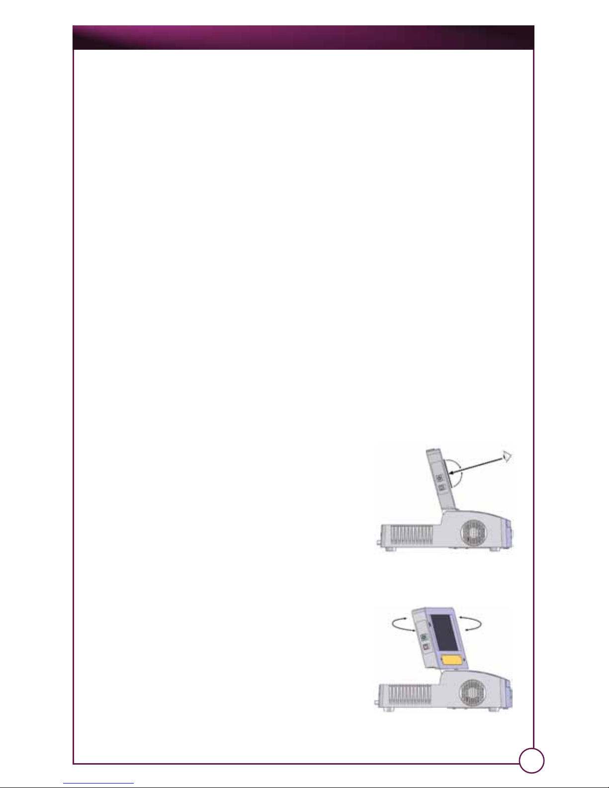
3.1.1 OnPoint System
For best performance, always operate and
keep the OnPoint unit on a flat, level, and
secure surface. Images on the Integrated
Video Display are best viewed at an angle
perpendicular to the display.
Do not tilt the OnPoint unit. For better viewing,
adjust the height and display angle.
14
Adjust display up/down for
Optimal Viewing Angle
Swivel display side-to-side
for Optimal Viewing Angle
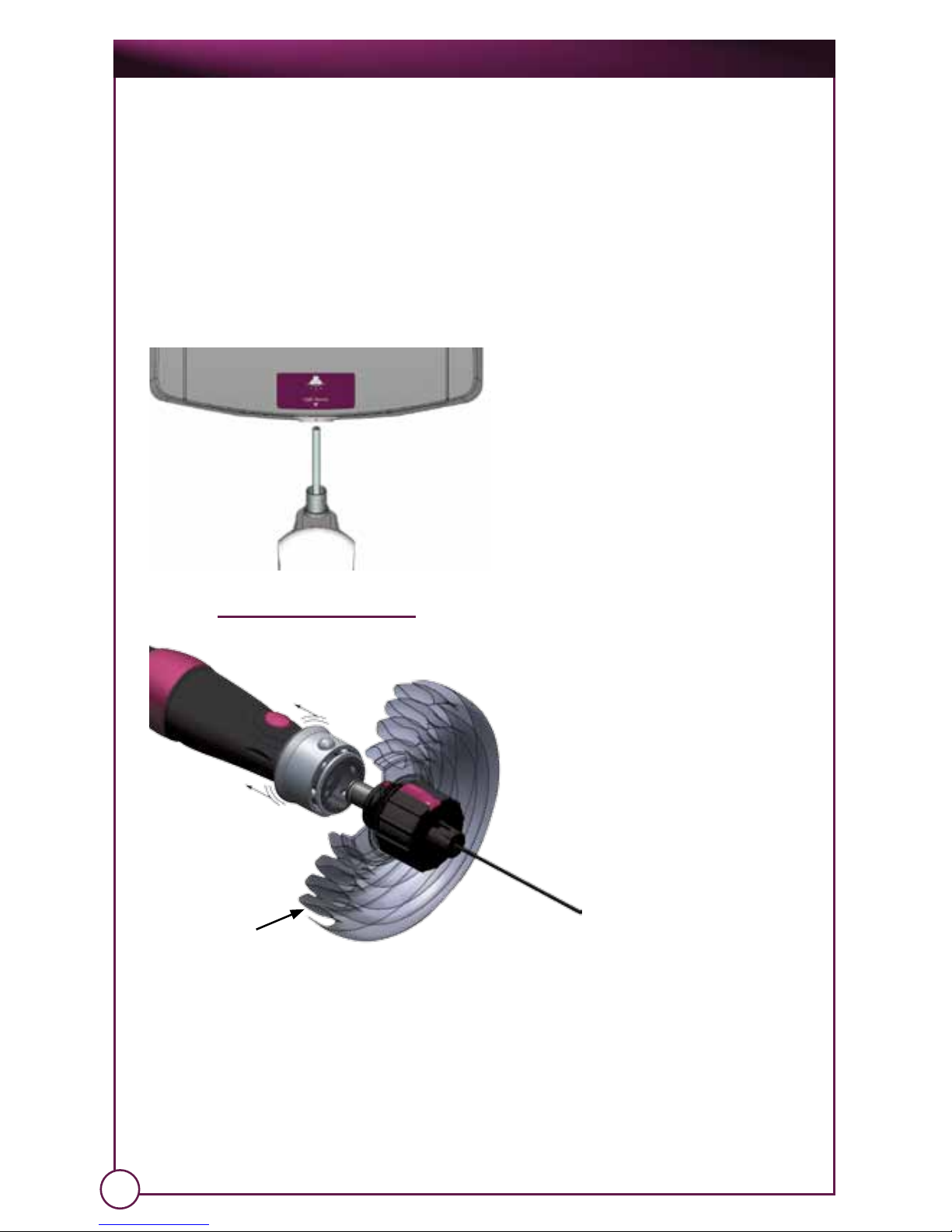
3.1.2 Attaching a Camera Handpiece and Arthroscope
The OnPoint camera handpieces attach via a combination fiberoptic/
electric connector. This connector seats in the receptacle on the front of
the unit (See also: § 2.2.1 Front).
Before connecting a camera or handpiece to the OnPoint™ unit, the camera or
handpiece must be properly cleaned (Ref. Section 4.0).
Note: For best image quality and to ensure patient safety, verify that both ends of the camera
or handpiece are free of foreign particles.
OnPoint™ Scope System
15
Pull Sliding
Sleeve
Drape
(Sectioned for illustration purposes)
Turn the power on. The monitor will power up within about fifteen (15)
seconds. Hold the distal tip of the scope approximately 2.0cm from a
surface with fine details such as your palm or surgical drape.
Turn the focus adjustment knob in either direction until the fine-detailed
surface at the distal end of the scope comes into optimal focus on the LCD
video monitor.
See also: § 3.2.2 Setup for Each Procedure
Connect the scope to the camera
by pulling the sliding sleeve and
inserting the scope. Ensure that the
light port is aligned with the bottom
of the handpiece and the red dot
on the back of the scope lines up
with the coupler top-indicator.
Release the sliding sleeve to secure
the scope in place. The proper
technique must be utilized in order
to preserve the sterile field through
the drape that is attached to the
endoscope.
Operation and Care Manual
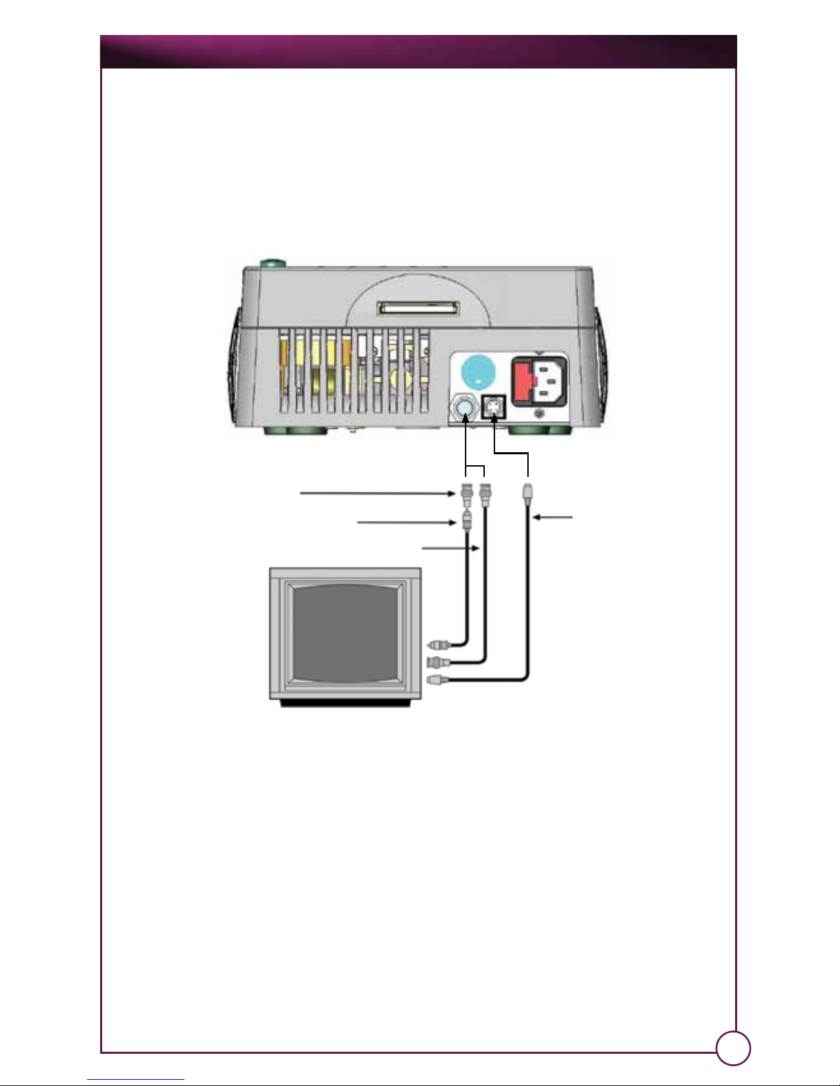
3.1.3 Attaching External Video Devices
In some cases, you may need a larger display than what is provided by the
OnPoint™ Integrated Video Display. For this reason, the OnPoint unit has
connections for multiple video outputs.
The OnPoint can be connected to a standard video monitor or an S-Video
monitor, or both. Consult your monitor manual for the corresponding
connections.
16
S-Video Cable
(not included)
BNC to RCA Adapter (included)
RCS Cable (not included)
BNC Cable (not included)
TV monitor
To make these connections, plug the connecting cable(s) into the video
output(s) on the rear of the OnPoint™ and the corresponding video input(s)
of the external devices.
A BNC-to-RCA adapter is supplied with the OnPoint for use with an RCA
cable, so that such connections can be made with an RCA cable as well
as a BNC cable. The adapter allows an RCA cable to be plugged into the
BNC video output on the rear of the OnPoint video box.
Note: The S-Video connector on the back of the OnPoint is rotated 45 degrees to the left. Most
S-Video cables have an arrow on the connectors to indicate the “top” of the connector. Finding
this arrow and rotating it to the left will help when connecting this type of cable to the OnPoint.
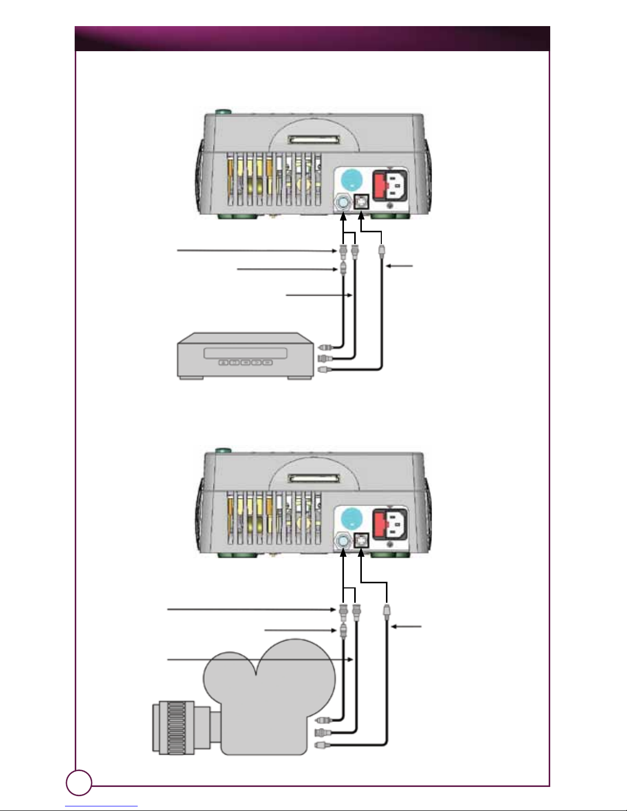
The OnPoint™ can also be connected to a standard VCR/DVR. Consult your
VCR/DVR manual for the corresponding connections.
The OnPoint can also be connected to a standard camcorder. Consult
your camcorder manual for the corresponding connections.
S-Video Cable
(not included)
BNC to RCA Adapter
(included)
RCS Cable
(not included)
BNC Cable
(not included)
VCR/DVR
Camcorder
S-Video Cable
(not included)
BNC to RCA Adapter
(included)
RCS Cable
(not included)
BNC Cable
(not included)
OnPoint™ Scope System
17
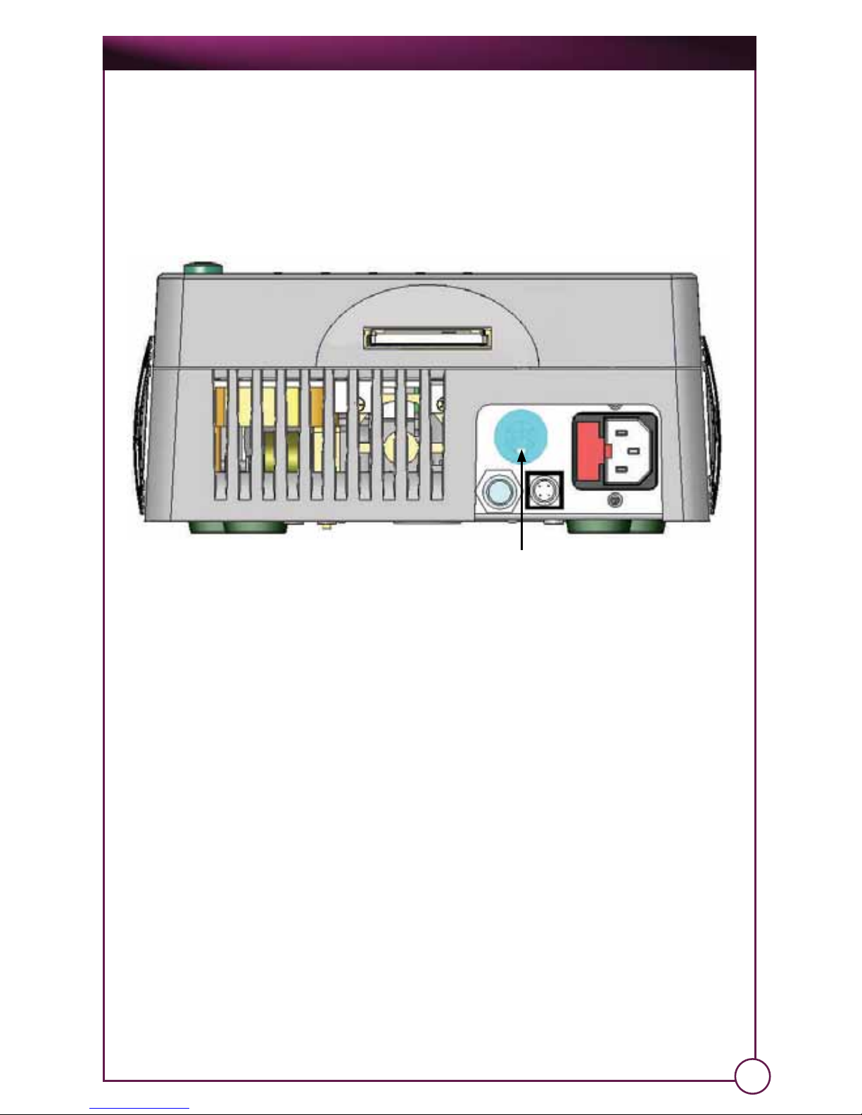
3.1.4 Attaching Virtual Reality Glasses
1. To attach the iWear VR glasses, simply take the connector on the end of
the glasses and find the 6-pin connector on the back of the OnPoint™.
2. To disconnect the iWear VR glasses, pull the knurled ring on the glasses
connector directly away from the OnPoint unit. The ring will move and
the connector will disconnect.
Operation and Care Manual
3.1.5 Setting Up and Operating MediaCaptureUSB
The MediaCaptureUSB is a full-featured, fully integrated image-capture
system that is included with every OnPoint™ system. MediaCaptureUSB is also
able to be activated from the sterile field via the camera connected to the
system. Your hand never has to leave the camera to capture what you
need.
Note: All functions that appear on the OnPoint display are also projected on any external display
(e.g. computer monitor, BioVision VR glasses, etc.).
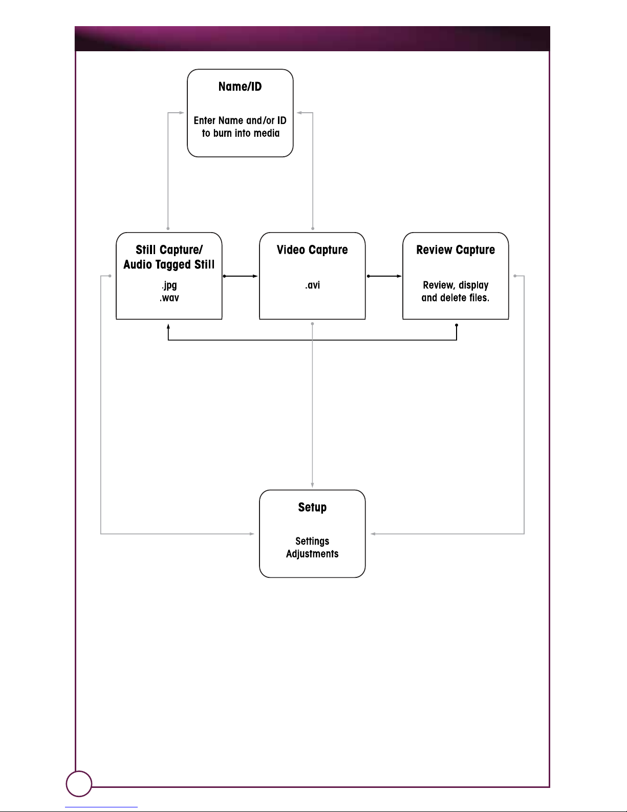
3.1.5.1 Modes
The MediaCaptureUSB has three separate modes of operation:
1. Still Capture Mode – for capturing still images (“pictures”)
2. Video Capture Mode – for capturing video images (“movies”)
3. Image/Video Review Mode (or “Review Mode”) – for reviewing image
captures (available only if a CompactFlash® card is inserted in the
OnPoint™ system’s media slot, and the card already contains captured
media).
There is a little red dot on the cable connector and the receptacle. When these are aligned, the
plug can be inserted into the receptacle.
iWear VR Glasses Connector
18
OnPoint™ Scope System
Note: If you have audio tag recording enabled, you can also include audio with any still images
you capture. Refer to the Setup section for more information on audio tag recording. Audio tags
are always recorded with video image captures.
Note: The OnPoint system will beep every time you press a button on the MediaCaptureUSB panel
(just under the OnPoint display).
To move between the different modes – in the above order – press the Mode
button under the OnPoint™ display (or press the F5 key on your keyboard).
3.1.5.2 Accessories & Attachments
You can also connect different accessories to your OnPoint system:
Note: Refer to Section 2.2.1 for the location of connectors.
19
Table of contents
Other BIOMET Medical Equipment manuals

BIOMET
BIOMET EBI Bone Healing System User manual

BIOMET
BIOMET innerVue II User manual

BIOMET
BIOMET VANGUARD XP User manual

BIOMET
BIOMET OrthoPak User manual

BIOMET
BIOMET Vanguard CR User manual

BIOMET
BIOMET SpinalPak User manual

BIOMET
BIOMET EBI Bone Healing System User manual

BIOMET
BIOMET 2001A User manual


