BioSmart PV-WM-MU User manual

Version 029.1
Date 03.2021
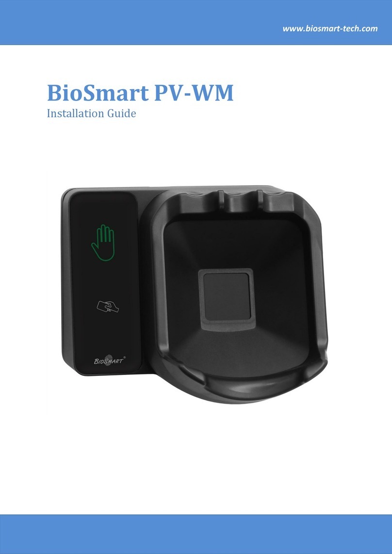
BioSmart PV-WM Reader
Operation Manual

Operation Manual BioSmart PV-WM v.029.1|03.2021|en
Page 2 of 24
CONTENTS
Introduction ..................................................................................................................................................................................................................... 3
1Description of Reader Operation ..............................................................................................................................................................4
Purpose ..............................................................................................................................................................................................................4
Technical Characteristics........................................................................................................................................................................4
Composition.................................................................................................................................................................................................... 5
Construction and Work ........................................................................................................................................................................... 5
Measuring instruments, tools and accessories ........................................................................................................................9
Marking and Sealing..................................................................................................................................................................................9
Packaging.......................................................................................................................................................................................................10
2Intended Usage ................................................................................................................................................................................................... 11
Operating Restrictions ............................................................................................................................................................................ 11
Preparing the Product for Use........................................................................................................................................................... 11
The Product Installation ........................................................................................................................................................................ 12
2.3.1 Choosing the Reader Location................................................................................................................................................. 12
2.3.2 Guidelines for Cable Routing .................................................................................................................................................... 12
2.3.3 Actions Immediately Before Connection.......................................................................................................................... 12
2.3.4 Installation Procedure .............................................................................................................................................................. 13
2.3.5 Connection to BioSmart UniPass Controller................................................................................................................... 17
Checking the Reader's Functionality............................................................................................................................................ 18
Reader Faults and Method of Its Elimination.......................................................................................................................... 18
PV-WM Reader Settings........................................................................................................................................................................ 19
Procedure for Performing Product Application Tasks .....................................................................................................20
3Maintenance for Intended Usage...........................................................................................................................................................23
4Miantenance.........................................................................................................................................................................................................23
5Storage and Transortation ..........................................................................................................................................................................23
6Utilization................................................................................................................................................................................................................23

Operation Manual BioSmart PV-WM v.029.1|03.2021|en
Page 3 of 24
BioSmart PV-WM Reader
Operation Manual
Dear Customers!
Thank you for purchasing our product. Subject to the installation and operation rules, this device will
serve for many years.
Introduction
This operating manual (OM) applies to the BioSmart PV-WM reader and contains information on the
principle of operation, technical characteristics, installation procedure and operating conditions, as well as
information on the conditions of transportation, storage, maintenance and maintenance of the reader in a
working condition.
Installation, adjustment and operation of the BioSmart PV-WM reader should be carried out by
personnel who have studied this manual.

Operation Manual BioSmart PV-WM v.029.1|03.2021|en
Page 4 of 24
BioSmart PV-WM Reader
Operation Manual
1Description of Reader Operation
Purpose
The BioSmart PV-WM reader is used as part of the BioSmart biometric access control and
management system in accordance with the BioSmart UniPass controller.
The BioSmart PV-WM reader is intended to read biometric data of a human palm vein pattern and
RFID-tag (card) code with subsequent transfer of the read information to the BioSmart UniPass or BioSmart
UniPass-EX controller via Ethernet.
The device is intended for use in premises, the operating conditions in which correspond to those
specified in this OM.
The device can be used outdoors if the following conditions are met:
installation is carried out in accordance with the requirements of this manual, taking into
account the provision of protection against dust and moisture penetration;
the reader is used in conjunction with a protective visor for
BioSmart PV-WM;
the operating conditions of the reader do not go beyond the operational limits (see par. 2.1).
Technical Characteristics
Technical characteristics are in the Table 1.
Table 1 –Reader technical characteristics
Parameter
Value
Biometric ID
Palm vein
Biometric Scanner Type
Optical, infrared
Built-in RFID tag reader
Yes
Communication interface with the control computer
Ethernet (IEEE 802.3u,
100BASE-TX)
Maximum cable lenght Ethernet, m
100
Indicators
Buzzer and LED indicator
DC supply voltage, V
12 ± 15 %
Maximum consumed current, A
0,4
PoE support
IEEE 802.3af class 3
Case material
Palstic
Dimensions, mm
185 x 160 x 134
Net weight, g
550
Gross weight, g
880
Ambient temperature during operation, °С
From -40 to +50
The upper value of the relative air humidity during operation at
a temperature of 25 С, %
95
Enclosure protection
IP65
Depending on the format of the RFID-tags (cards) used, appropriate versions of the readers are
provided. The list of versions is given in Table 2.
The list of RFID-tags formats read by BioSmart PV-WM, depending on the version of the reader, is
given in the reader's passport.
Table 2 –List of the BioSmart PV-WM reader versions Construction
Execution
Note
BioSmart PV-WM-EM
For reading EM-Marine format card
BioSmart PV-WM-MF
For reading Mifare format card
BioSmart PV-WM-LG
For reading Legic format card
BioSmart PV-WM-IC
For reading HID iClass format card

Operation Manual BioSmart PV-WM v.029.1|03.2021|en
Page 5 of 24
BioSmart PV-WM Reader
Operation Manual
Execution
Note
BioSmart PV-WM-MU
Multi-format reader
BioSmart PV-WM-MFR
Multi-format reader
Composition
The BioSmart PV-WM reader consists of the following parts:
reader case;
reader board;
biometric palm vein scanner;
RFID-tags (cards) reader.
The reader case consists of a front panel and a back cover with a mounting plate.
The back cover of the reader can be removed to provide access to the reader board.
The reader board is designed to connect the power supply and the BioSmart UniPass controller.
The palm vein scanner is designed to obtain users biometric data.
RFID-tags reader is intended to read the applied RFID-tags (cards) code.
Construction and Work
The reader is designed as a functionally complete device in a standard case.
The appearance and purpose of the main elements of the reader is shown in Figure 1 and Figure 2.
Figure 1 –Front view and purpose of the reader main elements
RFID-card
reader field
Retainer
(arrester)
between
fingers
Palm vein
scanner
Wrist retainer
(arrester)
LED indicator

Operation Manual BioSmart PV-WM v.029.1|03.2021|en
Page 6 of 24
BioSmart PV-WM Reader
Operation Manual
Figure 2 –Rear view of the back cover of the reader and the purpose of the main elements
The reader, powered and connected to the BioSmart UniPass controller, enters into palm/card
standby mode, according to the set operating mode.
During operation, the controller cyclically polls the status of connected readers. When an object is
brought to the palm vein biometric scanner, this object parameters are analyzed. If the attached object is
recognized as the palm of a living person, and biometric data of sufficient quality may be read from the palm,
then the biometric data is scanned in the infrared range by PV-WM. The read biometric data is transferred
to the BioSmart UniPass controller. Next, the obtained biometric data is compared with the palm vein
patterns stored in the database. If a template was found in the database, deviations from which fall within
the specified limit, the access settings prescribe to grant access to the appropriate employee. BioSmart
UniPass performs the actions specified in the working model for this situation and sends a message about
successful identification to the reader BioSmart PV-WM. If the template is not found in the database or the
access settings instruct to deny access, then the controller performs other actions prescribed by the working
model. For example, controller sends a message about failed identification to the reader. A failed
authentication message is being sent. Then there is a return to cyclic polling of the reader’s state.
If the object attached to the reader is recognized as an RFID-tag (card), then the BioSmart PV-WM
reads the RFID-tag code and transmits it to the controller. Upon the code receipt, the controller compares it
with the codes stored in the database. If a match is found and the access settings instruct the corresponding
employee to be allowed access, then the controller performs the actions specified in the working model for
this situation. For example, the controller activates the relay and controls the reader indication. If no match
Mounting
holes
Back cover
Cable
entry hole
Mounting
plate

Operation Manual BioSmart PV-WM v.029.1|03.2021|en
Page 7 of 24
BioSmart PV-WM Reader
Operation Manual
is found or the access settings prescribe to deny passage, then the controller performs other actions specified
in the working model. For example, BioSmart UniPass controls the sound signal on the reader.
Detailed information about operating modes is given in User Manual BioSmart UniPass.
The LED indicator displays the current reader status (see Figure 3).
Figure 3 –The reader LED indicator
The following display modes are set by default:
blue flashing - palm / card standby mode;
red single - notification about unsuccessful identification;
red flashing - there is no connection with the BioSmart UniPass controller or the reader is “not
tied” to the controller;
green single - notification about successful identification;
green flashing - firmware is being flashed (written) to the reader.
The reader board contains terminals for connectors for connecting power, external devices, as well as
LED indicators and switches.
A picture of the reader board is shown in Figure 4.
LED
Indicator

Operation Manual BioSmart PV-WM v.029.1|03.2021|en
Page 8 of 24
BioSmart PV-WM Reader
Operation Manual
Figure 4 –Reader board image
Clip connectors description of the reader board is given in Table 3.
Table 3 –Clip connectors description of the reader board
No
Marking
Description
Purpose
1
GND
Power supply, common wire
Common wire of power supply 12V
2
+12V
Power supply, +12V
«+» power supply 12V
3
Ethernet
Ethernet connector
with PoE support
Ethernet connector for connection to the
BioSmart UniPass controller
Note - The BioSmart PV-WM reader is intended for use in conjunction with the BioSmart UniPass
controller, which powers the readers through PoE technology, and therefore the GND and +12 V connectors
on the reader are used only as backup power connectors.
The green RUN LED on the reader board during the reader normal operation lights up once every two
seconds for 200 ms.
The jumpers are described in Table 4.
1
2
3

Operation Manual BioSmart PV-WM v.029.1|03.2021|en
Page 9 of 24
BioSmart PV-WM Reader
Operation Manual
Table 4 –Jumper description
Designation
Purpose
IP RST
Reset the IP-address setting
BOOT (Х2)
The reader transition into debug mode
Jumper BOOT (X2) is intended to switch the reader to debug mode (bootloader). This mode allows to
restore the reader operability if the firmware is damaged. To put in debug mode, close the BOOT (X2) jumper
when the power is off and turn on the reader power. Two seconds after turning on the reader power supply,
open the contacts.
In debug mode, the green RUN LED on the reader board blinks with a period of 1 sec (0.5 sec on, 0.5
sec off).
The reader may be powered from the BioSmart UniPass controller via an Ethernet cable using PoE
technology, or from a 12V DC voltage source connected to the clips on the reader board.
To power the reader from a DC voltage source, connect the "+" (plus) of the power supply to clip 2 on
the reader board, and source “-” (minus) - to clip 1.
The recommended type of power cables and their length are shown in Table 5.
Table 5 –Recommended power cable types
Power supply
method
Maximum
length, m
Cable type
Ethernet (IEEE 802.3)
100
A cable consisting of four twisted pairs of a category
not lower than the fifth with a cross-section of each
wire not less than 0.2 mm2
Power supply cable
50
Double-core cable with a cross-sectional area of each
core not less than 0.75 mm2
Power supply from a DC voltage source is carried out at a voltage of 12V with an output current of 1A.
The allowable range of the supply voltage is 10.2 - 13.8V. To prevent the device from malfunctioning due to
incorrect power connection, a protective diode is provided in the circuit board.
The BioSmart PV-WM readers are connected to the BioSmart UniPass controller via the Ethernet
interface.
Measuring instruments, tools and accessories
Installing the reader requires the following tools and accessories, listed in Table 6.
Table 6 –The list of tools and tackles
No
Names of tools and tackles
Notes
1
8P8C connector
For mounting the connector ("crimping") of
the Ethernet cable
2
Сrimping tool for Ethernet cables
3
Crosshead screwdriver
To lift off the cover and install the back cover
of the reader
During the operation of the reader, measuring instruments, tools and accessories are not required.
Marking and Sealing
The reader board is marked with element designations and the manufacturer's logo.
The warranty seal is installed on the reader board.
A serial number label is located on the inside of the scanner bowl and on the back of the reader, next
to the metal mounting plate.
There is a manufacturer's label on the back cover of the reader under the mounting plate. The
packaging is marked with transport markings containing handling symbols:

Operation Manual BioSmart PV-WM v.029.1|03.2021|en
Page 10 of 24
BioSmart PV-WM Reader
Operation Manual
Crushable. Caution
Protect from moisture
Stacking limit 5 kg
The packaging is labeled:
package size;
gross weight, net weight;
name of the consignee;
name of the consignor;
point of departure.
Packaging
The BioSmart PV-WM reader in accordance with its completeness, is placed in a consumer package,
which is a cardboard box with inserts made of uncrosslinked polyethylene foam.
The packaging used is intended for storage and transportation of the reader in accordance with the
conditions specified in paragraph 5.
Passport, fasteners are additionally packed in a plastic bag.
Box size (mm): length 238, width 205, height 185.
The cardboard box is non-toxic and safe to handle. It is a flammable material. Non-cross-linked
polyethylene foam liners and liner bags are highly flammable materials with high smoke-generating
capacity.
The packaging should be removed from open flames, heating devices and lighting to prevent fire.
The shelf life of the packaging is unlimited.
No special measures are required to the packaging dispose.

Operation Manual BioSmart PV-WM v.029.1|03.2021|en
Page 11 of 24
BioSmart PV-WM Reader
Operation Manual
2Intended Usage
Operating Restrictions
The reader must be operated in accordance with the technical characteristics specified in
paragraph 1.2.
During the reader operation, exposure to vibration and shock loads exceeding the following values is
not allowed:
sinusoidal vibration in the frequency range 5 - 100 Hz with an amplitude of 30 m/s2;
impacts with an amplitude of 50 m/s2.
The reader may be operated in the ambient temperature range from minus 40 to plus 50 С.
It’s not allowed to install the reader in close proximity to heat sources and under the influence of direct
sunlight in order to avoid overheating of the reader.
The reader must be installed in accordance with the requirements of paragraph 2.3.
If the requirements of paragraph 2.3 are met (to ensure protection against moisture ingress into the
case), the reader may be operated in accordance with the degree of dust and moisture protection IP54 in
accordance with conditions (dustproof with protection against water falling on the housing in the form of
splashes). Impacts not falling under the IP54 protection degree are not permitted. Such unacceptable effects
are, in particular, a jet of water directed at the case or the device immersion in water.
If the requirements of paragraph 2.3 are not met, then the reader won’t be protected against dust
and moisture. In this case, use of the device in a dusty environment and the ingress of liquid on the case is
not allowed.
To ensure dust and moisture protection, violation of the integrity of the reader body (holes, chips,
cracks) is not allowed.
The reader may be used outdoors only if the following conditions are met:
the device is not in the open air, but covered with a canopy, roof or a special canopy for
BioSmart PV-WM;
all requirements of paragraph 2.3 have been met to ensure protection against dust and
moisture ingress.
The device can be operated at a relative humidity of not more than 70% at a temperature of 25 С.
Moisture condensation is not allowed.
The device is not intended for use in aggressive and / or explosive environments.
Operation of the reader under conditions of ionizing (radiation) exposure is not allowed.
The device must be operated in conditions that exclude the influence of biological factors, such as
mold fungi, insects, animals.
Unqualified intervention in the reader design (namely, repair, improvement or any design changes)
by unauthorized persons is not allowed.
Preparing the Product for Use
1. Security measures:
Only persons who have studied this operating manual and who have permission to work with
electrical installations up to 1000 V, who have the necessary knowledge in setting up network equipment
and OS Windows administration, are allowed to install and configure the terminal.
When servicing the product, observe the safety regulations applicable when working with energized
equipment.
It is forbidden to carry out installation, commissioning of the product during a thunderstorm, due to
the danger of electric shock during lightning discharges from interference on the communication line.
All work on installation and connection of devices must be carried out with the supply voltage
disconnected.
The product is not intended to use in flammable and explosive environments. Burning of the plastic
included in the product may release toxic combustion products
The safety of the operating personnel when working with the terminal is ensured through the use of
a safe low voltage supply.
After the reader has been exposed to low temperature or high humidity conditions, it must be taken
out of the package and kept in a dry room at a temperature of (20 ± 5) С for at least 30 minutes before turning
it on.

Operation Manual BioSmart PV-WM v.029.1|03.2021|en
Page 12 of 24
BioSmart PV-WM Reader
Operation Manual
2. Scope and sequence of the device external inspection
After receiving the reader, make an external examination of the product to check the integrity of the
packaging, no damage.
Open the product packaging, remove the reader and perform the reader initial inspection to check
damage.
Check the correspondence of the serial number of the reader to the number in the passport. The
reader serial number may be seen on the labels.
Check the completeness of the reader for compliance with the passport.
The Product Installation
2.3.1 Choosing the Reader Location
When choosing a place to install the reader, consider the following:
1) The reader is recommended to be installed only on a vertical surface at a height of 150-170 cm from
the floor, based on the convenience of positioning the palm on the reader and presenting the card.
2) The place of the reader installation should be chosen so that the light of direct sunlight or light from
other bright light sources doesn’t fall on the scanner surface. Otherwise, due to the illumination of
the optical scanner screen, the number of identification errors will significantly increase.
3) To minimize the mutual negative influence of the built-in RFID-card readers, it’s not recommended
to install the reader at a distance of less than 80 cm from other RFID-readers and other sources of
electromagnetic interference.
4) When installing the reader on a metal surface, the reading range of the RFID-card may decrease.
5) If the installation site is outdoors, it’s additionally necessary to ensure:
the presence of a canopy or a special visor over the reader, which prevents the influence of
atmospheric precipitation and other liquids on the reader;
taking measures to preserve the dust and moisture protection of the reader (see paragraph
2.3).
2.3.2 Guidelines for Cable Routing
Observe the following guidelines when routing cables:
1) The cables routing must be carried out in compliance with the operation rules of electrical
installations;
2) Don’t rout cables less than 30 cm away from sources of electromagnetic interference;
3) The intersection of all cables with power cables is allowed only at right angles;
4) Any cable extensions should only be made by soldering.
5) Leave a margin of length for the cables connected to the reader, sufficient to lead the reader away
from the wall and access the jumpers.
6) To connect the reader, use the types of cables shown in Table 5.
2.3.3 Actions Immediately Before Connection
Before connecting cables, check:
1) Absence of mechanical damage on the palm vein reader scanner surface, printed circuit board and
the device case;
2) The stripped ends of the cable for connecting the reader shouldn’t exceed 5 mm to avoid short
circuits.

Operation Manual BioSmart PV-WM v.029.1|03.2021|en
Page 13 of 24
BioSmart PV-WM Reader
Operation Manual
2.3.4 Installation Procedure
1) If the operating conditions require the installation of a protective visor for the BioSmart PV-WM
reader, install the visor. For instructions on how to mount the sun visor, refer to the operating
instructions for the visor.
2) On the reader, unscrew the screws holding the mounting plate and remove the plate from the back
cover.
3) Mark the attachment points of the reader by placing the mounting plate on the surface. The
dimensions of the mounting plate are shown in Figure 5.
Figure 5 –Mounting plate dimensions
4) If the installation is carried out without using a protective visor, then drill holes in the marking points
and install the dowels from the fastening kit. If a protective visor for the BioSmart PV-WM reader is
used, then it already has holes for fastening using the bolts included in the BioSmart PV-WM visor kit.
5) Carry out the cables routing in accordance with the recommendations stated in paragraph 2.3.22.3.2.
The cable must fit freely in the dedicated space on the mounting plate (see Figure 6).
65 ± 0,2
68 ± 0,2
86 ± 0,2
147 ± 0,2

Operation Manual BioSmart PV-WM v.029.1|03.2021|en
Page 14 of 24
BioSmart PV-WM Reader
Operation Manual
Figure 6 –Space for cable on the mounting plate
To ensure protection against the ingress of dust and moisture, the reader must be connected with
one Ethernet cable, which will then be pulled into the reader case through a sealed gland. Due to the fact
that the Ethernet cable connector won’t pass through the cable gland, the cable should be “crimped” after
pulling it through the sealed lead-in.
Check the absence of breaks, short circuits and mechanical damage in the cables.
6) Fix the mounting plate by screwing self-tapping screws into the dowels or screwing the screws into
the corresponding holes on the protective cover for BioSmart PV-WM.
7) Unscrew the screws on the back cover of the reader (see Figure 7), remove the back cover.
Figure 7 –Rear cover attachment points
8) Insert the Ethernet cable through the hole in the back cover of the reader, insert the connector into
the Ethernet port and secure the rear cover of the reader. To achieve the declared IP54 protection
degree, follow the steps below.
It’s recommend to take the following measures to ensure protection against dust and moisture,
regardless of the intended operating conditions, as taking these steps increases the device survivability.
Measures to ensure protection of the reader from dust and moisture:
a) install the sealed lead-in on the reader back cover. The sealed lead-in composition is shown in Figure
8.
Space for
cable
Rear cover
attachment
points

Operation Manual BioSmart PV-WM v.029.1|03.2021|en
Page 15 of 24
BioSmart PV-WM Reader
Operation Manual
Figure 8 –Sealed lead-in composition
Sequence of step:
screw the connecting branch of sealed lead-in from the side of the tooth-type coupling,
leaving a hole large enough to insert the cable to be fixed;
install a rubber seal ring on the connecting branch of sealed lead-in;
insert the connecting branch of sealed lead-in into the cable hole on the back cover of the
reader so that the rubber seal ring is tightly clamped between the outer side of the back cover
and the wide part of the nipple;
screw the fastening nut onto the connecting branch thread protruding from the back (inner)
side of the reader back cover.
b) with the sealed lead-in installed, connect the reader to the Ethernet network, for which do the
following:
insert the uncrimped end of the cable into the sealed lead-in and stretch the cable to the
required length, if it’s necessary first loosen the hold-down nut;
“crimp” the end of the cable in accordance with Figure 9;
tightly tighten the hold-down nut from the outside of the back cover;
insert the connector into the Ethernet port.
Hold-down
nut
Sealing disk
Connecting
branch
Rubber seal ring
Anchor nut

Operation Manual BioSmart PV-WM v.029.1|03.2021|en
Page 16 of 24
BioSmart PV-WM Reader
Operation Manual
Figure 9 –Installing the Ethernet Cable Connector
c) install the back cover of the reader on the reader in accordance with the following requirements:
attach the back cover to the reader case. Make sure that the sealing gum didn’t fall out of the
special groove and was firmly pressed by the protrusion on the back cover side;
fix the back cover with screws (see Figure 7). It’s important to check that the sealing gum
doesn’t squeeze out of the special recess while tightening the screws. Therefore, tighten the
screws on the back cover carefully, tightening each screw in turn.

Operation Manual BioSmart PV-WM v.029.1|03.2021|en
Page 17 of 24
BioSmart PV-WM Reader
Operation Manual
Figure 10 –A notch with a sealing rubber on the reader body and a protrusion on the back cover
9) Fix the reader on the mounting plate and fix with screws at the bottom end (Figure 11).
Figure 11 –Fixing the reader to the mounting plate
2.3.5 Connection to BioSmart UniPass Controller
1) The interaction between the BioSmart PV-WM reader and the BioSmart UniPass controller is
provided via the Ethernet interface.
2) No more than two BioSmart PV-WM readers may be connected to one BioSmart UniPass controller.
Readers connection scheme is on the Figure 12.
Mounts on the bottom of the
reader

Operation Manual BioSmart PV-WM v.029.1|03.2021|en
Page 18 of 24
BioSmart PV-WM Reader
Operation Manual
Figure 12 –Readers connection scheme
Checking the Reader's Functionality
To check the reader operability, put your palm to the palm vein scanner or a card of the corresponding
format to the card reader (provided that the reader is connected to a powered BioSmart UniPass controller).
A beep should sound, and the LED should display a successful or unsuccessful identification signal.
Reader Faults and Method of Its Elimination
Troubleshooting methods for some reader problems are shown in the Table 7.
Table 7 - Reader faults and methods of their elimination.
№
Fault description
Possible reason
Elimination method
1
The reader doesn’t
turn on
Insufficient supply voltage
Connect to another power supply
2
Reader doesn’t
respond to applied
palm/card
Connection with BioSmart
UniPass controller isn’t
established
Restart the BioSmart UniPass
controller and reader on power
supply. Make sure the reader and
controller are powered at the same
time
BioSmart UniPas controller
has a working model not
providing palm/card waiting
Check the working model BioSmart
SmartHub or the BioSmart UniPass
controller settings
3
The user can’t be
identified by the palm
veins
User's palm vein patterns are
absent in the Biosmart-Studio
software database
Check the user templates presence, if
it’s necessary, scan the palm veins
(see Biosmart-Studio User Guide or
User Manual BioSmart UniPass
Controller)

Operation Manual BioSmart PV-WM v.029.1|03.2021|en
Page 19 of 24
BioSmart PV-WM Reader
Operation Manual
№
Fault description
Possible reason
Elimination method
Access group is not assigned
to BioSmart UniPass
controller
Check access group assignment (see
Biosmart-Studio User Guide)
The palm vein patterns were
incorrectly registered (the
correct palm position wasn’t
observed when scanning)
Re-add the palm veins following the
recommendations for the palm veins
scanning (see the Biosmart-Studio
User Guide)
4
The user can’t be
identified by the card
There is no card code in the
Biosmart-Studio software
database
Check the user cards presence in
memory (see the Biosmart-Studio
User Guide and User Manual
BioSmart UniPass Controller)
Card format doesn’t match
the reader type
Make sure that the RFID-card type
used is compatible with the built-in
RFID-reader type
Access group is not assigned
to BioSmart UniPass
controller
Check access group assignment (see
the Biosmart-Studio User Guide)
In the case when the measures taken didn’t allow to eliminate the malfunction and in the event of
malfunctions that are not described in Table 7, it’s recommended to contact technical support.
PV-WM Reader Settings
After connecting the readers to the BioSmart UniPass controller and connecting the controller to the
local network, it’s necessary to specify the readers serial numbers. These actions are performed in the
controller's WEB interface.
Access to the controller's WEB-interface is carried out using a computer with a WEB-browser. To gain
access, it’s necessary to supply power to the controller and connect it to a PC. Make sure that routing is
configured between the computer and the controller, TCP port 8082 is open.
To enter the web-interface, enter the controller's IP-address in the browser line in the form
IP_address:8082. By default, the controller has an IP-address 172.25.110.71, so if the IP-address hasn’t
changed, enter 172.25.110.71:8082 into the browser line. The screen will display the form shown in Figure 13.
Figure 13 –Access wondow to the controller web-interface

Operation Manual BioSmart PV-WM v.029.1|03.2021|en
Page 20 of 24
BioSmart PV-WM Reader
Operation Manual
In the Login and Password fields, enter username and password. Installed by default:
Login: root;
Password: bioroot.
After successful authorization pass on the “Settings” tab and enter the serial numbers of the BioSmart
PV-WM readers in the corresponding fields “Ethernet port 1” and “Ethernet port 2” (see Figure 14). The serial
number of each reader is given in the passport and on the reader back cover.
Then click Save.
Figure 14 –Reader serial number recording
The controller will reboot and the readers indication will change to blue. This indication mode
indicates that the readers are ready for operation.
Procedure for Performing Product Application Tasks
To start using the reader, follow the steps:
connect the reader to the BioSmart UniPass controller via an Ethernet cable;
if it’s necessary, connect executive devices to the controller;
on the BioSmart UniPass controller select the working model (the reader operation mode in
accordance with the BioSmart UniPass controller operation manual);
make settings in the Biosmart-Studio v5 software (add employees, register biometric data,
assign access groups, etc. in accordance with the Biosmart-Studio v5 User Manual).
To pass identification by the palm veins pattern, place palm against the reader in accordance with
the recommendations (see Figure 15)
This manual suits for next models
1
Table of contents
Other BioSmart IP Access Controllers manuals
Popular IP Access Controllers manuals by other brands

Tidel
Tidel IES 50 Installation and startup guide

Benzoville Hardware
Benzoville Hardware SDGF-001 user guide
ektor
ektor EV-AWAC-KIT installation instructions
Texas Instruments
Texas Instruments TMS320C645X user guide

CrucialTrak
CrucialTrak Quattro Troubleshooting

BRAINTECH
BRAINTECH FM1000 series user manual
