BioSure EOS8131-CL User manual
INSTALLATION & OPERATION MANUAL
Model: EOS8131-CL [G3]
EOS8132-CL [G6]
EOS8134-CL [G9]
Thank you for purchasing BioSure Professional product
Please read the instructions carefully and follow the safety precautions when using this
product.

General Information
2
Installation
7
Operation
12
Maintenance
20
Troubleshooting
24
1
4
2
5
3
The illustrations used in this Instruction Manual may vary from the actual
product that you have purchased.
EOS816X-ENG_V1.0
Table of Contents

IMPORTANT SAFETY INSTRUCTIONS
READ AND FOLLOW ALL INSTRUCTIONS
Read this manual completely before attempting installation, operation or servicing.
•Follow all applicable electrical codes.
•Electric shock hazard. Be sure to turn power OFF before servicing. Failure to do so
could result in serious injury or death.
•Do not operate with any panels or covers removed.
•Hazardous levels of ozone may be trapped in the system after a fault condition or when
power is turned off during operation. Always ensure ozone has been purged by allowing
Ozone Generator to complete its shutdown sequence before servicing.
•Short term inhalation of high concentrations of ozone and long term inhalation of low
concentrations of ozone can cause serious harmful physiological effects. DO NOT inhale
ozone gas produced by this device.
•Do not store or use gasoline, chemicals or other flammable liquids or vapors near this or
any other appliance.
SAVE THESE INSTRUCTIONS
CAUTIONS AND GENERAL NOTES
This manual covers all BioSure Professional G Series Electrolytic Ozone Generators,
Models G-3/6/9.
Any variations in system operation or configuration between models are noted in the text.
BioSure Professional reserves the right to make changes to the product covered in this
manual. Use this manual only with its original product. Although every effort has been
made to ensure accuracy of the information contained in this manual, BioSure
Professional assumes no responsibility for inadvertent errors.
WARRANTY SUMMARY
•Two (2) years on entire Ozone Generator.
•One (1) year on replacement parts.
•To prevent voiding warranty, follow all installation instructions and ensure that an
authorized BioSure Professional technician has commissioned the unit prior to first start-
up. After commissioning, the end user is responsible for all routine maintenance outlined
in Section 4 of this manual.
1
1.1 Production Description
The G series Ozone Generators described in this manual applies BioSure Professional’s
Indirect Electrolytic Ozone Generation (iEOG) technology to generate ozone gas in high
concentrations. This advanced ozone technology enables ozone to be formed steadily
from water with NOx-free and 28wt% high purity results. They are designed to support
modular application so that they can be easily integrated into all types of systems for
ozone applications.
The G series systems contain all elements necessary for the production ozone
electrolytically from municipally treated and filtered tap water. They are designed to
operate under vacuum, typically engaging with suction provided by a self-priming mixing
pump or venturi injector in a side stream of the process flow.
Follow the instructions in this manual carefully to ensure safe and reliable operation of the
G Series Ozone Generator Systems.
1.2 Ozone Generator Overview
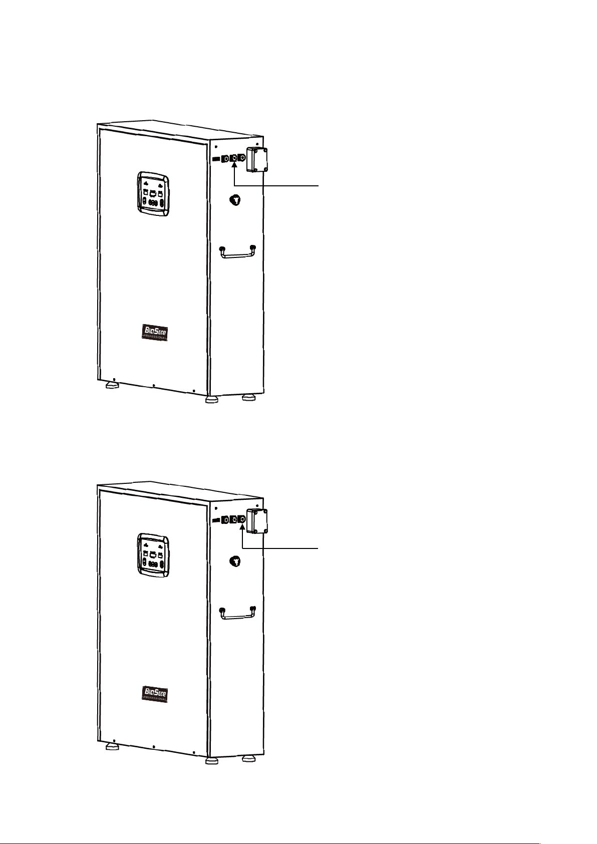
Refer to Figure 1 & 2 below for an overview of the G Series Ozone Generator, system
connections and panel descriptions. Labels are provided on the Ozone Generator near
selected connections to assist in proper installation.
2
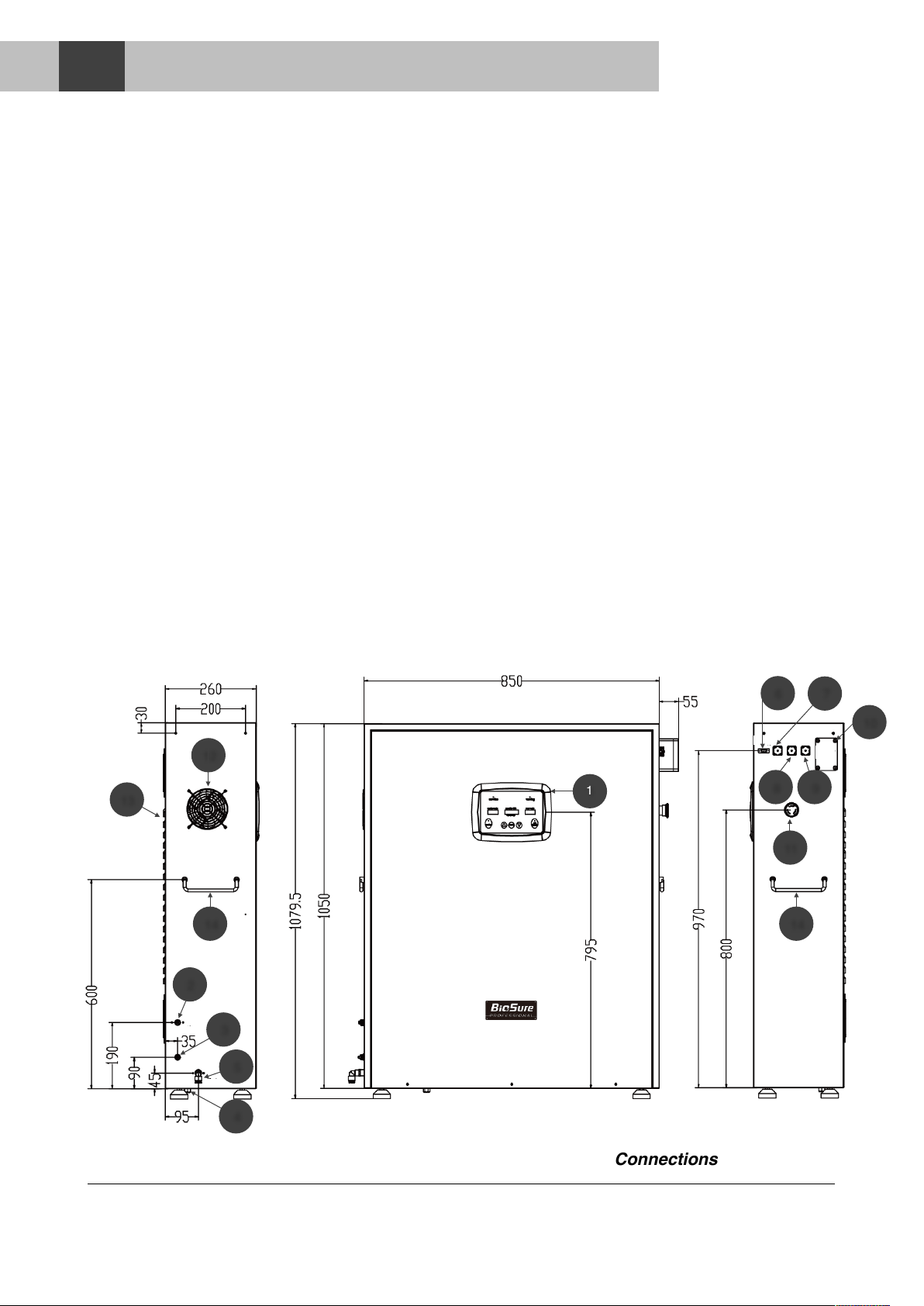
Figure 1. G Series Dimension Drawing Showing Connections
1
2
3
5
6
7
8
9
10
11
14
14
12
13
4
GENERAL INFORMATION
1

Captions
1. Operator Interface Panel (OIP)
2. iEOG Feed Water Inlet, 3/8”
3. Ozone Gas Outlet, 3/8”
4. Exhaust Outlet (Oxygen)
5. Drain Outlet, 7x10
6. Programming Port (DB9)
7. OWS Parallel Communication Port
8. External Signal Control Port (DC 5-12V)
9. External Circuit Control Port (ON/OFF)
10. Electrical Terminal Box
11. Mains Switch / Emergency Stop Switch
12. Side Air Inlet
13. Rear Air Outlet
14. Carry Handle(s)!
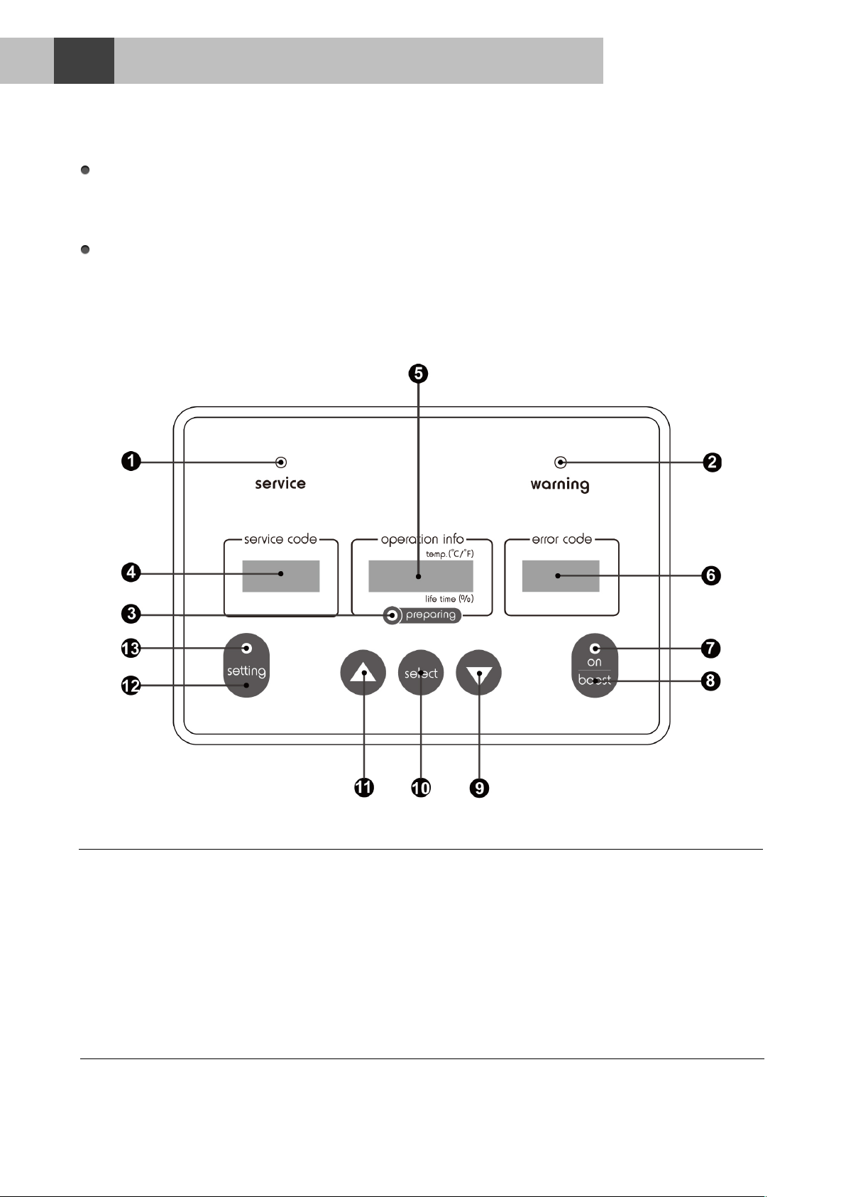
Captions
1. Service Indicator (Yellow)
2. Warning Indicator (Yellow)
3. Preparing Indicator (Green)
4. Service Code Screen
5. Operation Information Screen
6. Error Code Screen
7. Operation Indicator (Green)
8. [Cancelled Button]
9. Page-Down Key
10. Select/Enter Key
11. Page-Up Key
12. Setting Key
13. Setting Indicator (Green)!
3
Figure 2. G Series Operator Interface Panel (OIP) Descriptions

1.3 Ozone Generator Specifications
Engineering Configurations
System Code
G3
G6
G9
Model Number
EOS8131-CL
EOS8132-CL
EOS8134-CL
Ozone Production
3 g/h
6 g/h
9 g/h
Output Proportion
20-28 wt% O3(with 72-80 wt% O2)
Type of Ozone Generator
Indirect electrolytic ozone generation (iEOG)
Ozone Generation Source
Water (municipally treated water)
Principle of Setup
Central, Stationary Type (Point of Entry, POE)
Start Control Method
Signal Control
Off-gas handling
Built-in thermal catalytic process
Cooling Configuration
Air cool
IP Code
IP-X2
Noise Level
Max. 45 bB (at 1 m or 3.3 ft)
Dimensions
Width
905 mm
Depth
260 mm
Height
1079.5 mm
Weight
Net
60 kg
68 kg
75 kg
Gross
90 kg
98 kg
105 kg
Ambient Requirements
Location
For use on a hard, level, and stable surface only
Temperature
5 ~ 40°C (41 ~ 104°F)
Ventilation
Min. 5 air changes per hour
Clearance
Min. 10 cm (4”) clearance around unit
Power Requirements
Applied Power
□AC 220-240V, 50/60Hz
Rated Power
G3
300W
G6
600W
G9
900W
4

1.4 Functional Descriptions
Ozone (O3) is an active and unstable molecule consisting of three oxygen atoms. It is a
strong oxidizing agent, which is classed as particularly environmentally friendly as it
breaks down into oxygen. It is used especially in water for sanitation and disinfection
purposes.
The BioSure Professional G Series System produces ozone from water. The water in the
system is purified by reverse osmosis and ion-exchange and then dissociated by
electrolysis, the electrolysis cell uses a solid polymer membrane as electrolyte.
Using this membrane technology ozone can be produced by electrolysis from
demineralized water.
The main advantages of ozone production with a BioSure Professional’s G-Series
electrolytic ozone generator are as follows:
•Steady and concentrated ozone output promotes ozone dissolution and reactions.
•No feed gas preparation, as the ozone is produced from water by electrolysis.
•Performance independent to air (air quality, humidity and flow).
•No Nitric Oxides (NOx) formation (or formation of Nitrous Acid in water).
•No pure water input, as the pure water is self-prepared by the systems.
•No ionic contamination, as the water is dissociated using a solid polymer electrolyte.
•Easy integration and operation.
1.5 Ozone in Practice
Ozone itself is a colorless gas with a pungent smell. It is one of the strongest known
oxidizing agents. It has an electrochemical oxidation potential of 2.08 V. The ozone
molecule is only moderately stable and has a half-life in pure water and under normal
operating conditions of about 20 minutes. In the absence of oxidizable substances,
ozone decays to oxygen. In the presence of oxidizable substances, traces of CO2 will
also be formed.
Many years of experience show that an average ozone concentration of about 0.1 to 0.2
ppm (mg/L) is sufficient to maintain the colony forming unit (cfu) count in pure water
systems below 1 cfu per 100 ml.
Input Water Requirements - iEOG Feed Water
Conductivity
≤500μs/cm
Temperature
5 ~ 35 °C (41 ~ 95 °F)
Operating Pressure
2.0 - 7.0 kg/cm2(28.5 - 99.5 psi)
Flow Rate
≥300 LPH (1.3 GPM)
Others
pH 6~8; chlorine residual ≤0.1ppm; filtered to 1μm
5

1.6 Physical Properties of Ozone
*Normal conditions acc. to DIN1343: Pn = 1.01325 bar; Tn = 273.15°C, tn = 0°C
1.7 Intended Use
Applications
The BioSure Professional G Series ozone systems are used to produce ozone
electrolytically from water with promoted dissolution and disinfection performance and is
suitable for all types of industrial applications:
-Bottled Water Manufacturing
-Beverage Manufacturing
-Pharmaceutical Manufacturing
-Cosmetic Manufacturing
-Semi-Conductor Industry
-Personal Product Industry
-Foodstuffs Industry
-Industrial Cleaning Processes
-etc.
Ozone-containing gas or hydrogen should not be vented in an uncontrolled manner in
buildings or to atmosphere. The operator is responsible for the process and ensuring that
adequate safety precautions have been taken.
Molecular weight
47.9982
g/Mol
Density under normal conditions
2.144
g/L
Relative density
1.5582
g/L
Molecular volume under normal
22.387
m3/kMol
Boiling point (760 mm Hg)
-111.9 ± 0.3
°C
Melting point
-192.7 ± 0.2
°C
Critical temperature
-12.1 ± 0.1
°C
Critical pressure
54.6
atm.
Critical volume
111
cm3/Mol
Heat of vaporization
75.6
cal/g
Free energy (25 °C)
32.4
Kcal/Mol
6

Consult your local BioSure Professional dealer for installation arrangements. The
information described below in this section is intended for operator’s reference.
The most common configurations for common installation sites are discussed in this
section. For additional installation options or questions on your specific installation,
please contact your regional BioSure Professional dealer.
1. Pre-installation
Inspect the location for installation. Check for:
oSpace for the unit / Ventilation / ambient temperature
oWater supply flow and pressure
oDrain availability
oPower supply availability
Refer to the product specifications in Section 1.3 (P. 4-5) for all the requirements
and detail.
2. Location
The G-Series Ozone Generator is designed for location on the floor or support
plate. Place the unit on a flat and stable or similar placement surface to prevent
toppling and falling. Locate the unit out of reach of water splash and airborne
water with a degree of protection from dirt or other containments. Allow sufficient
access for maintenance and all piping. Other key requirements of the location are
as follows (Refer to Section 1.3, P. 4-5):
•Well ventilation - min. 5 air changes per hour
•A 10 cm (4”) minimum free air space must be maintained on all sides
•Climate-controlled, ambient temperature of 5° to 40°C (41° to 104°F)
3. iEOG Water Feed Pre-filtration
For water that enters the unit as input for iEOG water feed, the water quality must
meet our standards as follows:
oMunicipally treated tap water, 5 ~ 35 °C (41 ~ 95 °F)
oWater conductivity below 500 μs/cm, pH between 6 and 8
oFiltered to 1 μm with chlorine residual less than 0.1 ppm
BioSure Professional recommends that pre-filtration be installed on our products for
the input to the iEOG water feed. In most cases, treatment is needed to address
the removal of dirt, debris, sediment and chlorine residual. This stabilizes the iEOG
process resulting in maintained performance.$
The type of pre-filtration may vary with local water quality. Please see your local
BioSure Professional distributor for the best recommendation for your area.
Note: Filtration, or treatment, must be sized properly to be effective.
Inadequate flow and pressure will cause problem with operation of the unit.
7
INSTALLATION
2
4. Electrical
The G-Series Ozone Generator is supplied with an electrical terminal box on the
side for Power and Ground Connections. A hole underneath the box is provided for
conduit fitting.
Refer to specifications of the unit (Refer to Section 1.3) and your local electrical
codes for information on proper electrical connection. All permanent electrical
connections should be made by a qualified electrician.
Note: The circuit must be protected by a GFCI (Ground fault Circuit
Interrupter) installed in accordance with electrical codes.
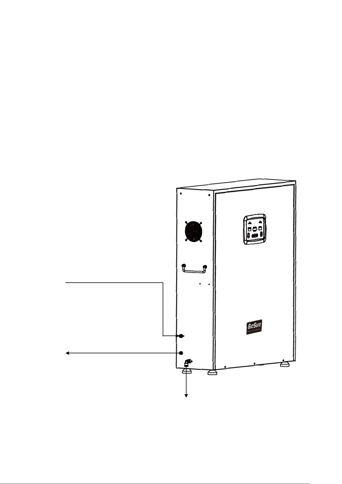
5. Connections
Water Input and Ozone Output
8
Water In
Ozone Out
•Press Connection.
•3/8” PE tube (white), included
accessory.
•Refer to specifications for
water quality requirements.
Drain
•Press Connection.
•3/8” PTFE tube, included
accessory.
•Quick Connection.
•7X10 PVC tube (black),
included accessory.
Figure 3. G-Series Water Input and Ozone Output Connections
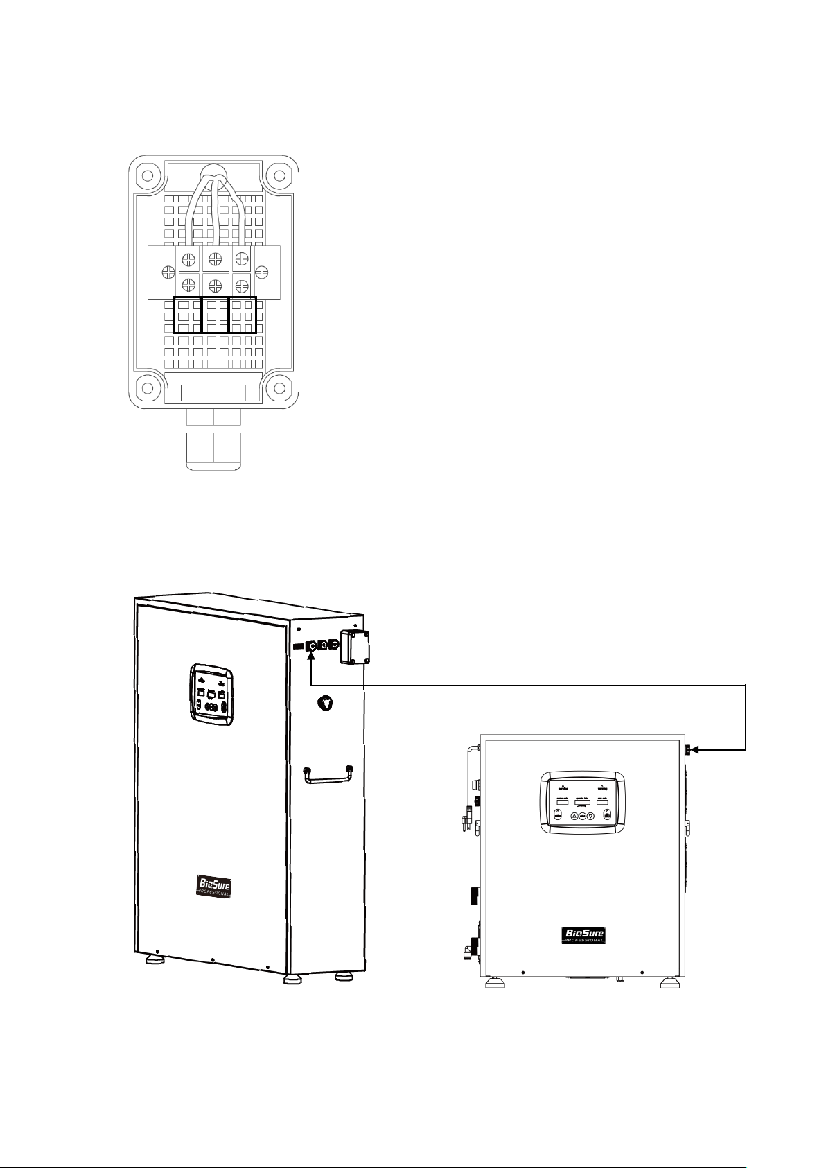
Electrical Connections
Control Connections
Model 1 - Operated with BioSure Professional OWS Series
9
N
L
E
Refer to Figure 3 for illustration of the Power
and Ground connections in the Electrical
Terminal Box.
Figure 4. G-Series Electrical
Terminal Box Power and
Ground Connections
Figure 5. G-Series Control Connection - Connecting with BioSure Professional
OWS-Series
OWS-1 (EOS8131-CD) Shown
Note: This complementary control wiring plug is
an optional accessory. Please contact your local
BioSure Professional distributor to order this
accessory if so needed.
Control Connections
Model 2 - Operated with an External Signal DC 5-12V
Control Connections
Model 3 - Operated with a Closed Contact Switch (ON/OFF)
10
Figure 6. G-Series Control Connection -
Connecting with a DC Signal for switching off
Supply DC 5-12V to switch off
operation.
Application: Safety control from ambient
ozone monitor
Note: This complementary control wiring
plug is an optional accessory. Please
contact your local BioSure Professional
distributor to order this accessory if so
needed.
Supply a closed contact for normal
operation.
Application: Remote Main switch or
timer control
Figure 7. G-Series Control Connection -
Connecting with a closed contact for normal
operation.
Note: This complementary control wiring
plug is an optional accessory. Please
contact your local BioSure Professional
distributor to order this accessory if so
needed.

6. Material Compatibility
In order to avoid ozone leaks, all materials coming into contact with ozone must be
completely ozone compatible. Acceptable materials include stainless steel, glass,
Hypalon, Teflon (PTFE), PVDF, etc.
As a general rule, the following minimum material qualities are recommended:
•Stainless steel ASTM 316 L for wet ozone gas
•PTFE, PVDF or Viton Gaskets for wet and dry ozone gas
11
3.1 Correct and Proper Use
The G-Series Ozone Generator MUST remain connected to the supply of power and
water AT ALL TIMES. This is because the stability and sustainability of the iEOG’s
performance is highly reinforced by the continuance of connected power and water
supply to the system.
Installation in an environment where temperatures may exceed 40°C can impair cooling
performance and may result in system overheat. The system will shut down
automatically for protection once inside temperature exceeds 44°C.
3.2 Descriptions of OIP Display and Button Functions
Captions
1. Service Indicator (Yellow)
2. Warning Indicator (Yellow)
3. Preparing Indicator (Green)
4. Service Code Screen
5. Operation Information Screen
6. Error Code Screen
7. Operation Indicator (Green)
8. [Cancelled Button]
9. Page-Down Key
10. Select/Enter Key
11. Page-Up Key
12. Setting Key
13. Setting Indicator (Green)!
12
OPERATION
3

“Service” Indicator (Yellow)
At the top-left corner is the “Service Indicator”, flashing in two modes to indicate the
service is required and the degree of urgency to the requirement:
“Warning” Indicator (Yellow)
At the top-right corner is the “Warning Indicator”, flashing to indicate an error and the unit
has stopped operating:
“Preparing” Indicator (Green)
The “Preparing Indicator” will light solid-on or flash to indicate three different status for
iEOG’s preparation conditions:
“Service Code” Screen
When service is due, together with flashing service indicator, this screen displays service
code to notify the required item(s) for replacement.
In addition, it will also display a number from 1 to 6 together with display of “Operational
Code” in “Operation Info” screen. As the “Operation Code” are divided and displayed in
groups of 6, here this number from 1 to 6 is displayed for identification of the group
numbers (Refer to Service Manual in addition).
LED Mode
Interpretation
Slow Flashing Yellow
[On 0.5S/Off 0.5S]
Servicing parts approaching the end of lifecycle (2%
remaining).
Quick Flashing Yellow
[On 0.1S/Off 0.2S]
Servicing parts reached the end of lifecycle.
LED Mode
Interpretation
Quick Flashing Yellow
[On 0.1S/Off 0.2S]
Error encountered and operation is stopped.
LED Mode
Interpretation
Solid ON Green
iEOG preparation in process (pure water refilling).
Slow Flashing Green
[On 0.5S/Off 0.5S]
iEOG re-start protection (30 min suspended).
Quick Flashing Green
[On 0.1S/Off 0.2S]
iEOG preparation failure (PS. plus flashing warning).
13

“Operation Info” Screen
In the middle of the three screens is for “Operation Information” that can provide
information about various operational data:
“Error Code” Screen
On the far right of the three screens is for “Error Code” that will display error codes to
notify the occurrence of any self-detectable problems.
“ON” Indicator (Green)
At the right-bottom corner, on the “On/Boost” button is the “On” Indicator that will light
solid on when the unit is running under normal conditions:
Readings/Display
Display Conditions
Service Code
Indicate which part is required for replacement when
Service Indicator starts flashing.
Operational Code
Group Number
Associated with Operational Code, display numbers
from 1 to 6 to identify the groups.
Readings/Display
Display Conditions
Temperature
Under normal conditions (including normal standby
and running), display water temperature inside the unit.
Use “▲” (page-up) or “▼” (page-down) key under
standby mode to switch between degree Celsius (°C)
and Fahrenheit (°F) in the display based on preference.
Part’s Remaining
Life-span
Press “select” to display the remaining life span for
each consumable part. Use “▲” (page-up) or
“▼” (page-down) key under standby mode to roll up or
down. Press “select” again to return.
Operational Code
Press “setting” (hold 15 sec) to display the Operation
Codes for operating history. Refer to P.xx for further
detail.
LED Mode
Interpretation
Solid ON Green
System running.
14

“Select” Key
This button is used for operators to switch the display between the “Temperature” and
“Part Remaining Life-time”. Also, it can be used to cancel the display of “Operational
Code”:
“Setting” Key
The “setting” button is used for operators to activate the display of “Operational Code”:
“Setting” indicator (Green)
At the left-bottom corner, on the “setting” button is the “Setting Indicator” that will flash
slowly when the “Operational Code” is displayed.
Function
Conditions / Outcomes
Part Remaining
Life Span Display
(Press 0.3S)
To display the Part Remaining Life-Time in the
“Operation Info” screen. Use “▲” (page-up) or
“▼” (page down) key to switch the display of between
each part. Press the “select” again to return to standby
with temperature display.
Operational Code
Display Cancellation
(Press 0.3S)
To cancel the Operational Codes display.
Function
Conditions / Outcomes
Operation Code
(Press 15S)
Press and hold on the key for 15 seconds to activate
the display of Operation Codes. Use “▲” (page-up) or
“▼” (page down) key to switch between each
displayed codes group (6 groups in total). Press
“select” to return.
LED Mode
Interpretation
Slow Flashing Green
[On 0.5S/Off 0.5S]
Indicate “Operational Code” is being displayed.
15
Summary of Button Functions
3.3 Pre-Commissioning Check
Confirm all below points prior to start-up:
•All inputs, output and drain are correctly installed to their corresponding connections.
•The power supply meets the requirements as indicated in the product specifications.
•Input water pressure is 2-7 kg/cm2.
•The area of operation is well ventilated (Min. 5 air changes per hour).
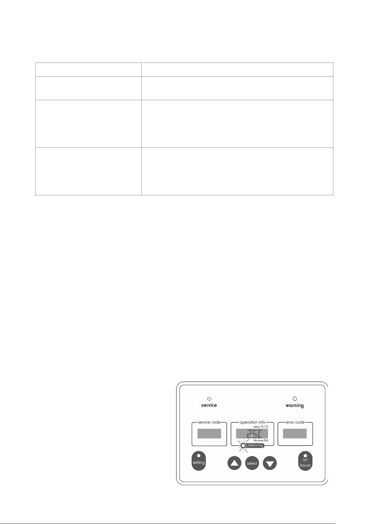
3.4 Initial Start-Up
The system is switched ON either controlled by OWS-Series or an external closed contact
switch. To use the machine at the first time, connect the machine to your selected signal
source for switching on and the “preparing” light will begin to flash slowly. At this point,
the machine is in preparation stage refilling water for iEOG start-up. This process will
take about 40 to 90 minutes depending on models, ambient and water temperature and
on-site water pressure.
Note: System draining during this stage is normal.
Functions
Operation Instructions
Switch temperature between °C
and °F
•Press “▲” (page-up) or “▼” (page-down) key under
standby mode.
Display part remaining life-time
information
•Press “select” key under standby mode (Temperature
display).
•Use “▲” (page-up) or “▼” (page-down) key to display
data.
•Press “setting” key to return.
Display operational code
•Press and hold on the “setting” key for 15 seconds to
display the system operation codes.
•Use “▲” (page-up) or “▼” (page-down) key to switch
between each displayed codes group.
•Press “select” key to return.
16
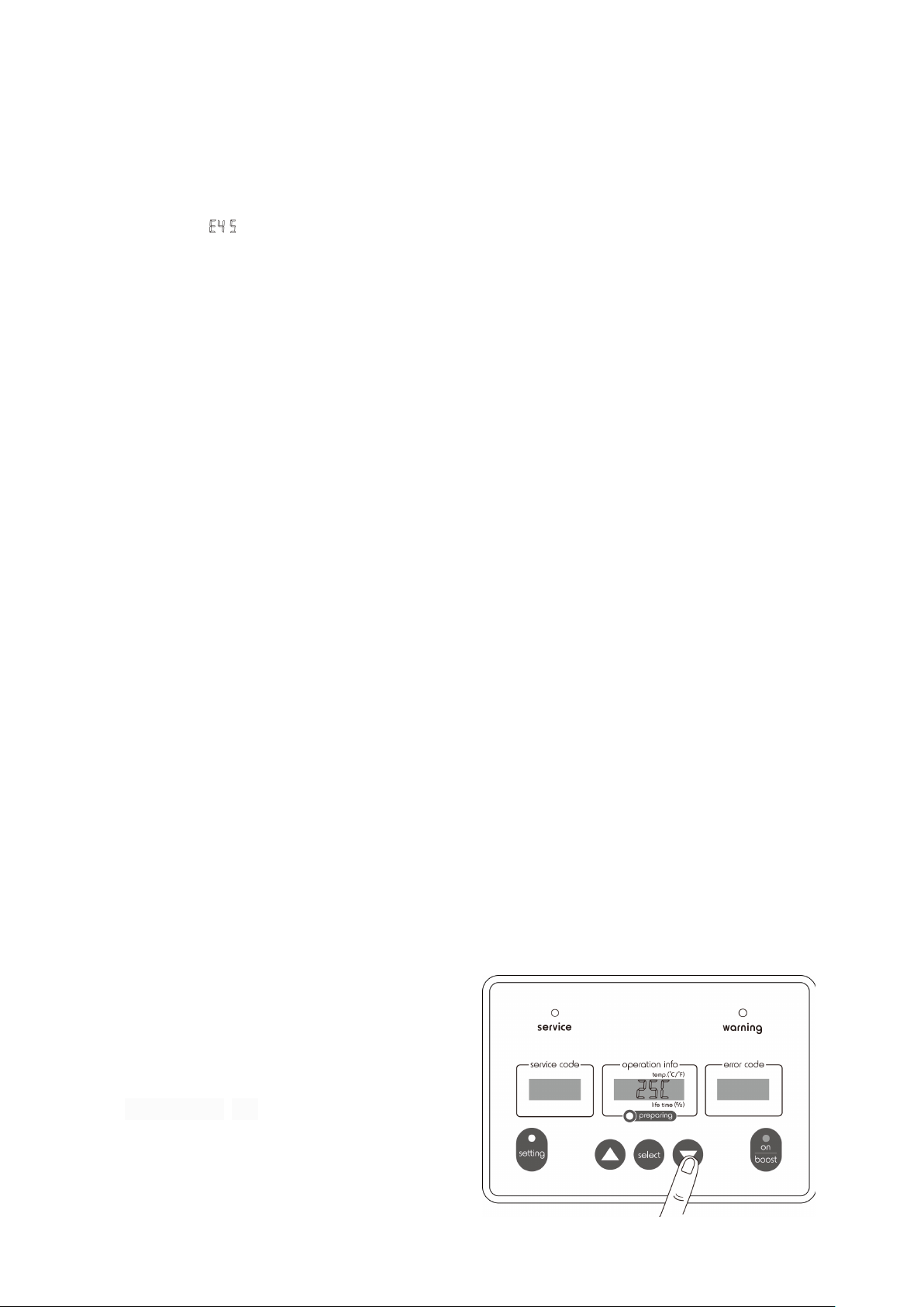
Once this preparation phase is complete, the “preparing” light will go out automatically,
and the system is now ready for normal operation. At this point, the panel displays the
detected water temperature inside the system on the “Operation Info” screen.
However, if in two hours the initial water filling process for iEOG start-up cannot be
completed, a “ ” error code will be displayed, indicating that the water filling process
was unsuccessful. All functions will remain suspended. Please check the input water
pressure and refer to the troubleshooting section on P.25 if the symptom is identified.
3.5 Shut-down, Re-Start & Power Disconnection Protection
The G-Series Ozone Generator is intended for being power connected and switched on
at all times, unless in necessary situations, such as to stop the unit for service or
relocation. The unit can be switched OFF by disconnecting the power supply or switching
off the Mains Switch / Emergency Stop Switch. Before shutting down the unit, the water
supply to the unit should be completely turned off.
Note: Disconnecting the power too often may cause unexpected impacts on the
iEOG module, which may result in degradation to the product performance.
To re-start the unit, simply reconnect the unit to power or switching on the Mains Switch
for switching on. However, after re-start all functions will be suspended for 30 minutes.
This is a standard protection procedure to minimize the impacts on the iEOG-working
module. During this “PROTECTION” period, system is running program for check and
maintenance.
3.6 Operation States
Starting and Running
The G-Series units are signal-controlled systems. Once a selected signal is available
(mastered by OWS-Series or a contact type ON/OFF circuit), the unit enters the “Running
State” automatically, which is also indicated on the OIP with “On” indicator lighting solid
on green. In this state, the electrolytic ozone generator module is running and ozone is
being delivered to the output. This ozone delivery will continue unless the signal is off to.
During the OFF period the ozone is destructed within the unit and discharged through
exhaust in the form of oxygen.
The G-Series units measure system temperature inside the unit and displays it on the
“Operation Info” screen for operator’s
reference. This display under all states as a
primary display comes as default in any new
unit. You can press “▲” (page-up) or
“▼” (page-down) under standby mode to
switch the unit between degree Celsius (°C)
and Fahrenheit (°F).
17
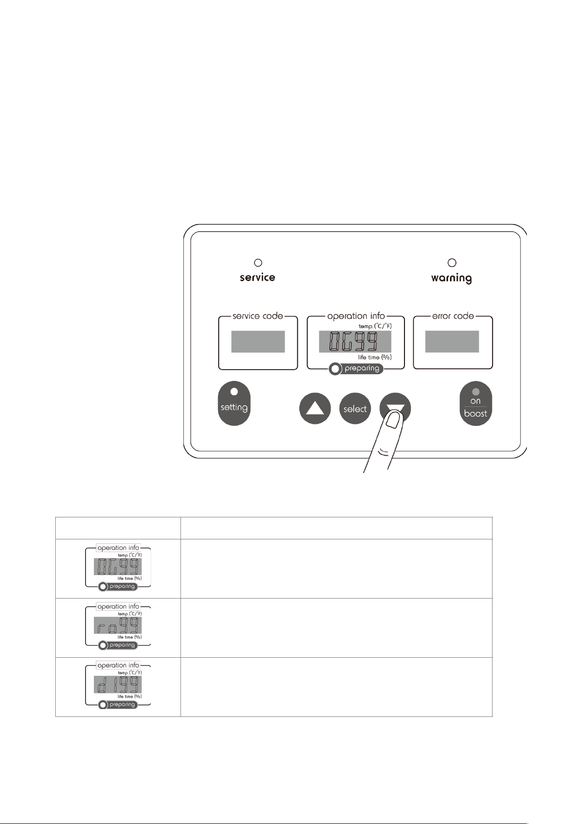
Display of Parts Life Cycle
The G-Series units record Remaining Life Cycle of each consumable part for operator’s
reference. The information is displayed on the “operation info” screen. Under standby
mode, press “select” button to switch the display for between the measured water
temperature and Remaining Life Cycle Information of each consumable part. The first
two codes represent the part and the following two indicate the Remaining Life Cycle in
percentage (%). Press “▲” (page-up) or “▼” (page-down) to switch the display for each
of the consumable parts equipped in the units for regular check purpose.
The coding system for the Remaining Life Cycle display is interpreted as follows:
Coding
Interpretation
Wording translation: OG99
Indicated part: EOG Cell(s)
Interpretation: Remaining life 99% for EOG Cell(s)
Wording translation: ro99
Indicated part: Reverse Osmosis (RO) Module
Interpretation: Remaining life 99% for RO Module
Wording translation: dI99
Indicated part: Resin Deionizer (DI) Module
Interpretation: Remaining life 99% for DI Module
18
This manual suits for next models
2
Table of contents
Other BioSure Cleaning Equipment manuals


Popular Cleaning Equipment manuals by other brands


Suevia
Suevia 130.5011 EASYCLEANER Mounting instructions

i-MO
i-MO Öko 2000 user guide

unGer
unGer Hydro Power Ultra UNP01 operating instructions

Black & Decker
Black & Decker BHPC130 Original instructions

Uni-ram
Uni-ram UG5000E operating manual

Axi
Axi MTC HC-300 Installation, operating and maintenance manual