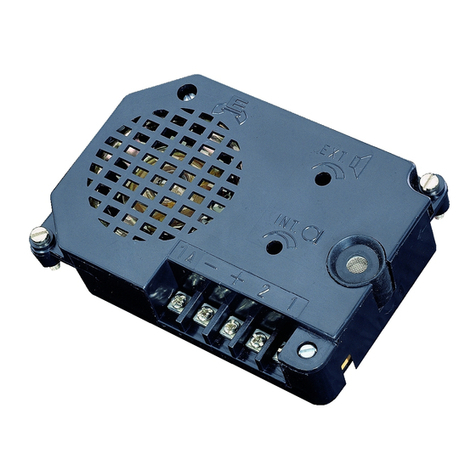
Bitron Video GCM80/21 User manual

cod. 012 175554.10
BITRON VIDEO s.r.l.
Via Torino 21/B - 10044 PIANEZZA (Torino) Italy
Tel. +39 011 968.46.11 (r.a.) - Fax +39 011 966.31.49
MANUALE ISTRUZIONE
CARATTERISTICHE DI FUNZIONAMENTO E INSTALLAZIONE
INSTRUCTIONS MANUAL
OPERATION FEATURES AND INSTALLATION
NOTICE
CARACTERISTIQUES DE FONCTIONNEMENT ET INSTALLATION
GCM80/21
AN 9540
GCM80/20
AN 9524
CITOFONIA • VIDEOCITOFONIA • TVCC • TELEFONIA

1
NOTA - NOTE
La piastrina porta-nome deve avere le dimensioni descritte.
The name-tag shall have the following dimensions.
La plaque porte-nom doit avoir les dimensions suivantes.
A
BC
A
1
B1 C1
A= 39 mm
B= 14,6 mm
C = 1,2 mm
A1 = 82 mm
B1 = 14,6 mm
C1 = 1,2 mm
4
3
2
P
CP
CH
CD
–
~
0
AP
0 12
0 230
AN 9524
AN 9540
AN1299
5
A
l morsetto 1 del citofono
To door phone terminal 1
A
la borne 1 du combiné
2
N.I. 012175554.
6
7
ab
TABELLA CONDUTTORI / WIRES DIAMETER AND CROSS SECTION / DIAMETRE ET SECTION DES CONDUCTEURS
CONDUTTORE / WIRE / CONDUCTEUR DISTANZE / DISTANCES / DISTANCES
50 mt 100 mt 200 mt 300 mt
Rif. FUNZIONE / FUNCTION / FONCTION
ØSez.
mm² ØSez.
mm² ØSez.
mm² ØSez.
mm²
1 Com. fonica - Speech com. - Com. phonie 0,8 0,5 1 0,75 1,2 1 1,4 1,5
2 Fonia e chiamata - Speech and call - Phonie et appel 0,8 0,5 1 0,75 1,2 1 1,4 1,5
0 Comune alimentazione - Supply common - Commun alimentation 1,2 1 -
~Alimentazione – Power supply – Alimentation 1,2 1
Ap Apriporta / Door opener / Gâche 1,2 1

DATI TECNICI
Alimentazione: ………………12 V c.a. (80 mA a riposo)
Dimensioni: …………………..…….. 110 x 120 x 56 mm
Peso: …………………………………………..….. 280 gr.
GENERALITA'
I moduli citofonici tipo GCM80/20 ( 0 tasti ) e GCM80/21 ( 1 tasto raddoppiabile ) sono stati progettati per realizzare impianti citofonici a 1 + n
fili, (1 filo comune + 1 filo per ogni citofono).
Il posto esterno di cui sono stati dotati costituisce l'unità di amplificazione fonica di tutto l'impianto citofonico.
Le funzioni principali del dispositivo sono:
1) Amplificazione delle fonie in entrambi i sensi
2) Generazione delle note di chiamata sia per il citofono che per la chiamata al piano
3) Conferma acustica di avvenuta chiamata
4) Funzione di disgiuntore fonico per impianti con segreto
COMPONIBILITA' VERTICALE
I supporti portamoduli (KSM 70/1 - KSM 70/2 e KSM 70/3) vengono forniti con la testata inferiore in plastica, già assemblata.
Per completare la pulsantiera è sufficiente inserire i/il modulo/i nelle apposite scanalature. Nel caso di montaggio di più moduli, interporre il
distanziale in plastica già fornito nel corredo dei supporti moduli, come indicato nelle tre figure presenti sulla scatola imballo.
Completare la preparazione della pulsantiera, inserendo la testata superiore e serrando a fondo, le due viti di chiusura testata, date a corredo.
Ricordare che nell'ultimo modulo in basso, ( quello a contatto con la testata inferiore ) occorre piegare di 90° le due forcelle
del comune pulsanti, come indicato in fig. 1 per evitare interferenze.
COMPONIBILITA' ORIZZONTALE
Le pulsantiere sono componibili anche in senso orizzontale (max 3 file). Per quest'applicazione, sono forniti con i supporti moduli, dei profilati di
accoppiamento da inserire nelle due scanalature esterne, dei supporti moduli adiacenti, prima di fissare le testate superiori. Quest'accessorio
consente di risparmiare l'utilizzo di cornici, garantendo comunque un perfetto allineamento delle pulsantiere.
(Come indicato nelle figure presenti sulla scatola imballo).
FISSAGGIO AL MURO
Murate opportunamente le scatole incasso procedendo come indicato nella fig. 2, utilizzando le viti di sicurezza a corredo e l'apposito utensile
in dotazione.
Eseguire i collegamenti elettrici, come da schema e chiudere la pulsantiera, ruotandola verso l'alto. Vedi fig. 3
APERTURA E TRASFORMAZIONE TASTO DA SEMPLICE A DOPPIO
L'accessibilità al cartellino portanome, è ottenibile utilizzando l'apposito attrezzo in dotazione, facendo leva, in uno qualsiasi dei quattro angoli
del copritasto.
Per la trasformazione del tasto da semplice a doppio, operare nel modo indicato. Gli accessori (portacartellini e cartellini) sono forniti a corredo
nei moduli tasti. Fig. 4
Ricordarsi sempre di tagliare il comune sulla parte posteriore della pulsantiera. Per le figure fare sempre riferimento alla
scatola imballo .
MORSETTI DI COLLEGAMENTO
AP Morsetto per serratura elettrica (chiusura a massa)
0 Negativo alimentazione dal trasformatore
~Alimentazione 12 Vca dal trasformatore
–Massa impianto (verso i citofoni)
CD Comune diodi (uscita fonia e apriporta)
CH Sensore e chiamata citofonica
CP Comune pulsanti (chiamata citofonica)
PChiamata al piano
COLLEGAMENTI
Per quanto riguarda i collegamenti, è opportuno tenere presente alcune regole fondamentali:
- rispettare accuratamente le sezioni indicate nelle tabelle a piè di schema.
- evitare di posare i cavi dell'impianto vicino a quelli della normale rete elettrica (almeno 30 cm di distanza).
- collegare i fili di massa esattamente come indicato in fig. 5per evitare ronzii.
Posizionare il trasformatore ad una distanza massima dal Posto Esterno, di 20 mt.
Utilizzare per la connessione dei terminali ~ e 0 dei conduttori da 1 mm². Rispettare inoltre scrupolosamente i collegamenti
indicati sullo schema, al fine di evitare ronzii sulla fonia
I morsetti di chiamata CP e P dovranno essere utilizzati esclusivamente per l’uso previsto onde evitare funzionamenti anomali
sulla fonia.
MONTAGGIO PIASTRA DIODI
Sui moduli pulsanti (PSM70), negli impianti citofonici 1 + n (moduli citofonici GMC80/20 – AN9524 e GCM80/21 – AN9540) si dovrà installare
la piastra diodi PDM70 - AN 6298 (Fig.7a)
La piastra diodi potrà essere montata indifferentemente a destra o a sinistra nel caso si utilizzi il tasto normale e su entrambi i lati qualora
vengano raddoppiati i tasti. I reofori dei diodi sono già a passo e dovranno essere serrati sotto gli appositi morsetti.
La piastra diodi è dotata di una morsettiera ove viene indicato il comune diodi (CD) ed inoltre un filo uscente anche lui collegato al comune
diodi. La piastra è confezionata a 4 elementi pre-tranciati e si può spezzare nella configurazione richiesta dal modulo pulsanti utilizzato.
Nei caso di utilizzo di tasti doppi ricordarsi di tagliare il collegamento comune del pulsante. (Fig.7b)
REGOLAZIONE DEI VOLUMI
Il posto fonico esterno, viene regolato in fase di produzione sui valori ottimali, per un impianto di media grandezza.
Talvolta, può rendersi necessario variare tale regolazione.
In tal caso procedere come segue:
- Volume esterno: agire sul trimmer EXT in senso orario, per aumentare il volume ed in senso opposto per ridurre il volume.
- Volume interno: agire sul trimmer INT in modo analogo al precedente.
COLLEGAMENTO COMUNE PULSANTI
Al fine di evitare ponticelli volanti, tutti i moduli pulsanti (incluso il modulo citofonico a 1 tasto, GCM80/21 AN 9540) portano sul lato inferiore
una forcella in corrispondenza del comune pulsanti.
Per il ripristino del comune pulsanti, tra modulo e modulo, sarà sufficiente allentare la vite (sul modulo più in basso) del primo pulsante, inserire
la forcella e richiudere le vite.
Se si utilizzano versioni di pulsantiere su più file, occorrerà utilizzare un filo di collegamento tra i due comuni pulsanti delle file.
E' inoltre sempre necessario, ponticellare il comune pulsanti di destra, con quello di sinistra, all'interno della stessa fila.
ESCLUSIONE CONFERMA DI CHIAMATA
Se la chiamata citofonica raggiunge il citofono, il posto esterno genera una nota di conferma; tale nota può essere disabilitata, tagliando il
ponticello sotto il coperchio di protezione del posto esterno, come indicato in figura 6.
PROTEZIONE AL CORTOCIRCUITO SULLA CHIAMATA
Un eventuale cortocircuito sui morsetti di chiamata, farà intervenire la protezione in corrente che interrompe le chiamate per alcuni secondi.
Trascorso tale tempo, il posto esterno sarà nuovamente in grado di generare una nuova chiamata e se non verrà eliminato il cortocircuito, il
ciclo si ripeterà.
I
4
MANUALE ISTRUZIONI – 012175554.
NOTA
NOTA
NOTA
NOTA

TECNICAL DATA
Supply: ………………12 V ac. (80 mA in stand-by)
Dimensions: ………………….. 110 x 120 x 56 mm
Weight: …………………………….……….. 280 gr.
GENERALITA'
I moduli citofonici tipo GCM80/20 ( 0 tasti ) e GCM80/21 ( 1 tasto raddoppiabile ) sono stati progettati per realizzare impianti citofonici a 1 + n
fili, (1 filo comune + 1 filo per ogni citofono).
The main functions of this device are:
1) Speech amplification in both ways
2) Generation of notes for the door phone call and for the call at the floor
3) Acoustic confirmation of the call
4) Speech separator function for systems with secrecy of conversation
VERTICAL MATCHING
The modules supports ( KSM 70/1 - KSM 70/2 e KSM 70/3 ) are supplied with the plastic lower head already assembled.
In order to complete the panel it is sufficient to insert the module/s into the appropriate openings. In case of several modules insert, between
modules, the spacer supplied with the modules support, as shown in the three drawings on the external packaging.
Complete preparation of the panel inserting the upper head and firmly fixing the 2 supplied screws.
Do not forget that the last lower module (the one in contact with the lower head) will have the two button commons forks
bent of 90° as indicated in drw. 1in order to avoid interferences.
HORIZONTAL MATCHING
The panel can also be matched horizontally (max 3 rows). For this application the modules supports are supplied with coupling profiles to be
inserted into the two external side grooves before fixing the upper heads. This accessory ensures a perfect alignment of the panels without
using finishing frames.
(As shown in the drawing on the external packaging).
WALL FIXING
After the boxes have been embedded proceed as indicated in drw. 2
Make electrical connections following the scheme and close the panel rotating it upwards. Drw. 3
HOW TO OPEN THE BUTTON AND TRANSFORM IT INTO DOUBLE
Access to the name tag is possible by means of the supplied key lifting any of the 4 button cover angles.
In order to transform the button from single into double, proceed as indicated.
The required accessories are supplied with the buttons modules.
Do not forget to always cut the buttons common in the panel rear part. Drw.4. In order to find the drawings please kindly look
at the external packaging ).
CONNECTION TERMINALS
AP Terminal for electric lock (closing to ground)
0 Supply negative from the transformer
~12V ac supply from the transformer
–System ground (towards the door phones)
CD Diodes common (speech output and door opener)
CH Detector and door phone call
CP Buttons common (door phone call)
PCall at the floor
CONNECTIONS
As far as connections are concerned, it is necessary to keep the following main points in mind:
- carefully follow the wires sections indicated in the tables at the bottom of the diagrams
- avoid placing the system's cables next to the mains' ones (at least 30 cm away).
- connect ground wires exactly as indicated in fig. 5in order to avoid buzzing.
Install the transformer at a max. distance of 20 mt from the loudspeaking unit. For connection of terminals ~ e 0 use 1 mm²
wires. Furthermore, carefully follow the connections indicated in the diagram, in order to avoid buzzing on the speech.
Call terminals CP and P shall be used only for the foreseen purpose in order to avoid anomalous operation on the speech.
DIODES PLATES MOUNTING
The diodes plate PDM 70 - AN 6298 shall be installed in buttons modules (PSM 70) when coupled to video modules or in 1 + n door phone
systems (door phone modules GCM80/20 - AN 9524 and GCM80/21 - AN 9540 ) (drw.7a).
The diodes plates shall be mounted either at the right or the left hand side, in case of standard button and on both sides when the button is
doubled
Diodes pins already have the proper dimension and shall be tightened under the appropriate terminals.
The diodes plate is equipped with a terminal board where the diodes common (CD) is indicated, as well as with an outgoing wire also
connected to diodes common.
The plate is foreseen for 4 pre-cut elements and can therefore be cut for the configuration required by the used buttons module.
When using the double button, remember to cut buttons common connection. (drw.7b)
VOLUMES ADJUSTEMENT
The loudspeaking unit is set, during production, on optimum values for a standard installation. If, however, such setting had to be changed it is
necessary to proceed as follows:
- External volume: act on EXT trimmer rotating it clockwise to increase the level and counter-clockwise to decrease it.
- Internal volume: act on INT trimmer in the same way as the previous one.
CONNECTION OF BUTTON COMMON
In order to avoid further connections, all the buttons modules (including the door phone module 1 button GCM80/21 AN 9540 ) have, on the
lower side, a fork in correspondance of the button common.
In the order to connect the buttons common between modules, it is sufficient to loosen the screw (on the lowest module) on the first button,
insert the fork and tighten the screw again.
When using several row panels, it will be necessary to use a connection wire between the two buttons commons of the rows.
It is in any case important to always connect a bridge between right and left buttons common inside the same row.
DISABLING OF CALL CONFIRMATION
When the door phone call reaches the door phone, the loudspeaking unit generates a confirmation note; this can be eliminated cutting the
bridge under the loudspeaking unit protection cover, as indicated in drw. 6.
PROTECTION AGAINST SHORT CIRCUIT ON THE CALL
A possible short circuit on call terminals will generate current protection that interrupts the calls for a few seconds. After this time, the
loudspeaking unit will again be able to generate a new call; if the short circuit continues the cycle repeats.
GB
6
INSTRUCTION MANUAL – 012175554.
NOTE
NOTE
NOTE
NOTE

DONNEES TECHNIQUES
Alimentation: ………………. 12 V c.a. (80mA in stand-by)
Dimensions: …………….………….…. 110 x 120 x 56mm
Poids: …………………………..………………...….. 280 gr.
GENERALITE
Les modules parlophones GCM80/20 (0 touche) et GCM80/21 (1 touche dédoublable) ont été conçus pour la réalisation de systèmes de
parlophonie à 1 + n fils.
Le micro HP dont ils sont équipés forme l’unité d’amplification phonique de tout le système de parlophonie.
Le fonctions principales du dispositif sont:
1) Amplification des phonies dans les deux sens
2) Génération de la note d’appel soir pour le combiné soit pour l’appel à l’étage
3) Confirmation acoustique de l’appel
4) Fonction de séparateur phonique pour systèmes avec secret
MONTAGE VERTICAL
Les supports de modules ( KSM 70/1 - KSM 70/2 e KSM 70/3 ) sont fournis avec la tête inférieure en plastique déjà assemblée. Pour
compléter la platine il suffit d'insérer le/les module/s dans les fentes appropriées. Dans le cas de plusieurs modules l'entretoise en plastique
fournie avec les supports de modules.
Compléter la préparation de la platine en insérant la tête supérieure et vissant à fond les 2 vis de fermeture fournie, comme indiqué dans les
trois dessins de la boîte extérieure.
Ne pas oublier que le dernier module en bas (celui en contact avec la tête inférieure) aura les deux fourchettes du commun
des touches pliées de 90° comme indiqué dans la dessin 1,pour éviter des interférences.
MONTAGE HORIZONTAL
Les platines peuvent être jumelées aussi horizontalement (max 3 rangées) .
Pour cette application les supports de modules sont fournis avec des profilés de jumelage à insérer dans les deux rainures extérieures des
supports d'à côte avant de fixer les têtes supérieures.
Cet accessoire garantit un alignement parfait des platines sans avoir à utiliser les cadres enjoliveurs.
(Comme indiqué dans le dessin de la boîte extérieure).
INSTALLATION MURALE
Après avoir maçonné les boîtiers d'encastrement, il faut procéder comme indiqué dans la dessin 2en utilisant les vis de sécurité et la clé
fournis avec le module. Effectuer les connexions électriques comme indiqué dans le schéma et fermer le module le tournant vers le haut .
Dessin 3
OUVERTURE ET TRANFORMATION TOUCHE DE SIMPLE EN DOUBLE
L'étiquette porte-nom est accessible en utilisant l'outil qui est fourni soulevant le plastique de couverture sur un des quatre angles.
Pour transformer la touche de simple en double, procéder comme indiqué.
Les accessoires sont fournis avec les modules touches. Dessin 4
Ne pas oublier de couper le commun des touches du côté postérieur de la platine. Les dessins se trouvent sur le boîtier
extérieur.
BORNES DE CONNEXION
AP Borne pour serrure électrique (fermeture à masse)
0 Négatif alimentation du transformateur
~Alimentation 12 Vca du transformateur
–Masse système (vers les combinés)
CD Commun diodes (sortie phonie et ouvre-porte)
CH Détecteur et appel de parlophonie
CP Commun des touches (appel de parlophonie)
PAppel à l’étage
BRANCHEMENTS
En ce qui concerne les connexions il faut tenir compte des points suivants qui sont très importants:
- respecter scrupuleusement les sections des fils indiquées en bas des schémas
- éviter de placer les câbles d'installation près des fils du réseau électrique (au moins à 30 cm de distance).
- brancher les fils de masse exactement comme indiqué dans le dessin 5afin d’éviter des ronflements.
Le transformateur sera placé à une distance max. de 20 mt du micro HP. Pour la connexion des bornes ~ et 0 utiliser des
conducteurs de 1 mm². Respecter aussi scrupuleusement les branchements indiqués dans le schéma pour éviter les
ronflements sur la phonie.
Les bornes d’appel CP et P devront être utilisées seulement pour l’emploi prévu afin d’éviter tout fonctionnement étrange sur
la phonie.
MONTAGE PLAOUE A DIODES
La plaque à diodes PDM 70 - AN 6298 sera installée sur les modules touches (PSM 70) jumelés à des modules vidéo ou dans les système de
portier électrique à 1 + n fils (modules GCM80/20 – AN9524 et GCM80/21 – AN9540) et modules touches relatifs. (dess.7a)
La plaque à diodes pourra-t-etre montée soit à droite soit à gauche dans le cas de la touche normale et des deux cotés lors de l'utilisation de la
touche dédoublbe. Les pins des diodes ont la mesure appropriée et devront être serrés sous les bornes relatives.
La plaque à diodes est équipée. d'un bornier où est indiqué le commun diodes (CD) ainsi que d'un fil en sortie lui aussi branché au commun
des diodes.
La plaque est prévue pour 4 éléments pré découpès et peut être cassée pour la configuration nècessaire au module touches utilisé.
Lorsque l'on utilise la touche double il ne faut pas oublier de couper le branchement des communs des touches. [dess.7b]
REGLAGE DES VOLUMES
Le micro-HP est réglé, pendant la production, sur des valeurs optimales pour une installation standard. Si, toutefois, il s’avérait nécessaire de
varier ce réglage, il faudrait agir comme suit:
- Volume extérieur: agir sur le trimmer EXT le faisant tourner dans le sens des aiguilles d'une montre pour augmenter le niveau et dans le
sens contraire pour le diminuer
- Volume intérieur: agir sur le trimmer INT de façon analogue.
BRANCHEMENT DU COMMUN DES TOUCHES
Pour èviter des pontets volants, tous les modules touches (y inclus les modules portier 1 touche GCM80/21 – AN9540) ont, sur le côtè
infèrieur, une fourche en correspondance des communs des touches. Pour rètablir le commun des touches entre un module et l'autre, il suffit
de desserrer la vis (sur e module plus bas) de la première touche, insérer la fourche et refermer la vis Si l'on utilise des versions de platines
sur plusieurs files, il faudra utiliser un fil de branchement entre les deux communs des touches des files Il faut en tout cas toujours brancher un
pontet entre le commun des touches de droite et celui de gauche à l'intèrieur de la meme file
EXCLUSION DE LA CONFIRMATION DE L’APPEL
Lorsque l’appel arrive au combiné le micro HP génère une note de confirmation; cette note peut être exclue en coupant le pontet qui se trouve
sous le couvercle de protection du micro HP, comme indiqué dans le dessin 6.
PROTECTION AU COURT CIRCUIT SUR L’APPEL
Un éventuel court circuit sur les bornes d’appel enclenche la protection en courant qui interrompt l’appel pendant quelques secondes. Après
ce temps le micro HP pourra de nouveau générer un nouvel appel; si le court circuit continue, le cycle se répète.
F
8
NOTICE - 012175554.
NOTE
NOTE
NOTE
NOTE

179 215 70
NB. TAGLIARE IL PONTICELLO DI RAME PRESENTE SUL CIRCUITO STAMPATO
DI TUTTI I CITOFONI AN 1000 – AN 7320 – AN 9300
NOTE: CUT THE JUMPER ON THE PCB OF ALL DOOR PHONES AN 1000 – AN
7320 – AN 9300
NOTE: COUPER LE PONTET DU CIRCUIT IMPRIME DE TOUS LES COMBINES
A
N 1
000
–
AN 7
3
2
0
–
AN
9300
IMPIANTO DI 1 POSTO ESTERNO CON
CHIAMATA ESTERNA ELETTRONICA
(+ CHIAMATA ELETTRONICA AL PIANO)
DOOR PHONE SYSTEM 1 ENTRANCE,
ELECTRONIC CALL
(+ ELECTRONIC CALL AT THE FLOOR)
SYSTEME PARLOPHONE 1 ENTREE AVEC
APPEL ELECTRONIQUE
(+ APPEL ELECTRONIQUE A L’ETAGE)
179 215 80
NB. TAGLIARE IL PONTICELLO DI RAME PRESENTE SUL CIRCUITO STAMPATO
DI TUTTI I CITOFONI AN 1000 – AN 7320 – AN 9300
NOTE: CUT THE JUMPER ON THE PCB OF ALL DOOR PHONES AN 1000 – AN
7320 – AN 9300
NOTE: COUPER LE PONTET DU CIRCUIT IMPRIME DE TOUS LES COMBINES
A
N 1000
–
AN 7320
–
AN 9300
IMPIANTO DI 2 POSTI ESTERNI CON
CHIAMATA ESTERNA ELETTRONICA
(+ CHIAMATA ELETTRONICA AL
PIANO)
DOOR PHONE SYSTEM 2
ENTRANCES, ELECTRONIC CALL
(+ ELECTRONIC CALL AT THE
FLOOR)
SYSTEME PARLOPHONE 2 ENTREES
AVEC APPEL ELECTRONIQUE
N.I. 012175554. N.I. 012175554.
This manual suits for next models
1
Table of contents
Languages:
Other Bitron Video Intercom System manuals
Bitron Video
Bitron Video AN9508 User manual
Bitron Video
Bitron Video AV1860/1 User manual
Bitron Video
Bitron Video AV1407/005 User manual
Bitron Video
Bitron Video AV1860/11 User manual

Bitron Video
Bitron Video GVM3000 User manual
Bitron Video
Bitron Video AV2058/52 User manual
Bitron Video
Bitron Video AV1407/010 User manual
Bitron Video
Bitron Video AN 9839 User manual
Bitron Video
Bitron Video MV1000 User manual
Bitron Video
Bitron Video AV1860/30 User manual


