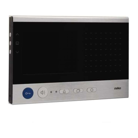
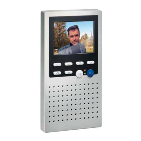
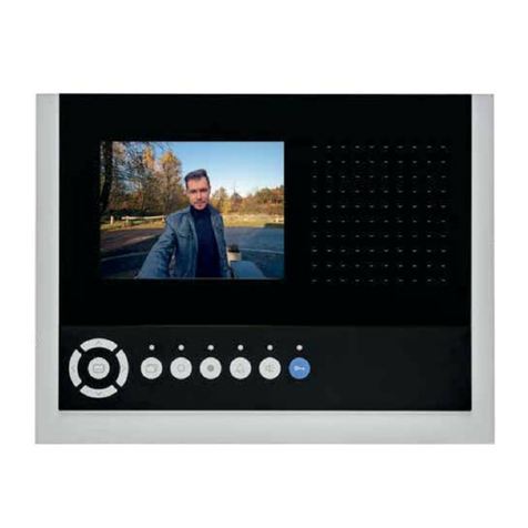
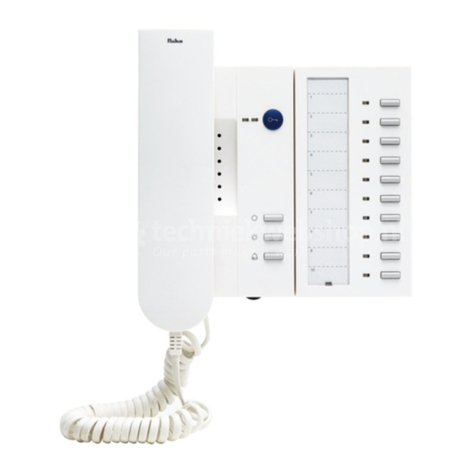
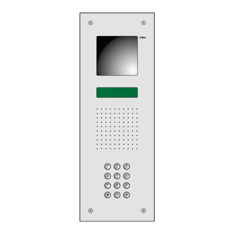
Niko 10-589 User manual

1
10-589
LEES DE VOLLEDIGE HANDLEIDING VÓÓR INSTALLATIE EN INGEBRUIKNAME.
1. BESCHRIJVING
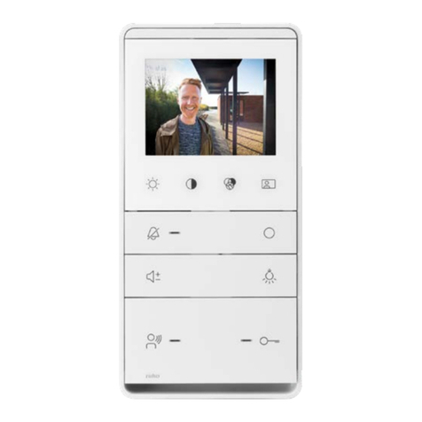
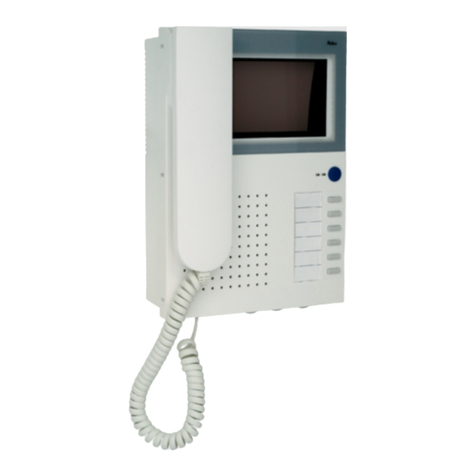
De videobinnenpost 10-589 uit het gamma Toegangscontrole Standaard maakt altijd deel uit van een systeem met één of meerdere buitenposten en
een voeding uit het gamma Niko Toegangscontrole Standaard.
Meer informatie over de integratie van het product in een volledig systeem vind je terug in de technische catalogus.
De videobinnenpost 10-589 biedt je standaard de mogelijkheid om:
• een deur te openen;
• een gesprek te voeren;
• het belsignaal uit te schakelen;
• verlichting te schakelen;
• camerabeelden op te roepen.
2. ONDERDELEN
Basisonderdelen
De videobinnenpost bestaat uit de volgende onderdelen:
toetsen om de beeldkwaliteit in te stellen
achterpaneel
jumpers
verbindingskabel
voorpaneel
etiketten met het serienummer van de videobinnenpost
Bijkomende benodigdheden
De videobinnenpost 10-589 moet 6-draads bekabeld worden.
Gebruik een getwiste kabel voor een optimale kwaliteit van het videobeeld.
Let daarnaast op de diameter van de aders in de kabel want deze bepaalt de maximum afstand die behaald kan worden tussen de voeding en de videobin-
nenpost.
Niko raadt aan om de volgende kabels te gebruiken voor de installatie van de videobinnenpost 10-589:
• JYSTY (-F2) min. 3 x 2 x 0,8mm (max. afstand 200m);
• TVVF (-F2) min. 3 x 2 x 0,8mm (max. afstand 200m);
• TPVF min. 3 x 2 x 0,6mm (max. afstand 100m);
• UTP/FTP/STP 4 x 2 x 0,5mm (max. afstand 70m).
Opmerking
• Bovenvermelde maximum afstanden zijn enkel geldig als er slechts één toestel actief is. Als er 2 monitoren parallel op dezelfde kabel werken, deel de
maximum afstand dan door 2. Bij 3 monitoren deel je door 3, enz.
• Je kan maximum 6 monitoren (lijn in en lijn uit) bekabelen. Als je meer dan 6 monitoren wil aansluiten of als je voor sterbekabeling kiest, gebruik dan
videosplitters. Aan elke uitgang van een videosplitter kan je opnieuw 6 monitoren aansluiten.
3. MONTEREN
Let op!
Installeer de videobinnenpost 10-589 niet onder spanning. Sluit het toestel pas na volledige installatie aan op de netspanning.
Ga als volgt te werk om de videobinnenpost te monteren:
➥1 Om de videobinnenpost te openen, steek je een
schroevendraaier in de opening onderaan het
toestel en duw je zacht tegen het voorpaneel.
NL

2
10-589
➥2Monteer het achterpaneel met geschikte schroeven tegen de muur.
oriënteringspijl die de richting van montage aanduidt
aansluitklemmen voor de aansluiting van de bedrading
montagegat voor de inkomende kabel
➥3Sluit de bedrading aan volgens het aansluitschema op pagina 6.
Opmerking
• Gebruik in één systeem dezelfde kleurencode voor dezelfde klemmen (a, b, P, ...) voor alle producten van het gamma Toegangscontrole
Standaard.
• De metalen behuizing kan geaard worden aan de klem
➥4Als het systeem meerdere binnenposten bevat, configureer je de afsluitweerstand via de jumper (J2) aan de binnenkant van het voorpaneel.
Standaard is J2 niet verbonden.
Deze binnenpost is niet het laatste toestel in lijn: J2 is niet verbonden.
Deze binnenpost is het laatste toestel: J2 is verbonden.
➥5Sluit het voorpaneel met de verbindingskabel aan op het achterpaneel.
➥6 Om de videobinnenpost te sluiten, plaats je het voorpaneel op het achterpaneel. Beide
panelen worden samengehouden door krachtige magneten.
NL

3
10-589
4. PROGRAMMEREN
Standaardfuncties activeren
Standaard zijn de volgende functies op de functietoetsen geprogrammeerd:
De deur openen.
Het belsignaal uitschakelen.
Het lichtrelais op de voeding schakelen.
Het camerabeeld van één of meerdere camera’s oproepen.
Een gesprek voeren:
• 2-richtingscommunicatie door éénmaal kort op de toets te drukken.
• 1-richtingscommunicatie (walkie-talkieprincipe) door de toets ingedrukt
te houden.
Een stuurfunctie uitsturen om een relais te bedienen.
Om deze functies te activeren, moet je enkel de videobinnenpost aan de buitenpost(en) koppelen.
Alternatieve functies programmeren
Je kan aan enkele van de functietoetsen ook de volgende alternatieve functies toekennen:
Als er geen gesprek gestart is: het licht aanschakelen.
Als er een gesprek gestart is, behoudt deze toets zijn standaardfunctie, namelijk de deur openen.
Etagedeur openen. Zie hoofdstuk ‘Etagebeldrukknop activeren’.
via de voeding of het servicetoestel
Als er een gesprek gestart is, het gesprek beëindigen.
Als er geen gesprek gestart is, behoudt deze toets zijn standaardfunctie, namelijk het belsignaal onder-
drukken.
via het servicetoestel
Een tweede interne oproep maken. via het servicetoestel
Eén van deze functies:
• Een eerste interne oproep maken.
• De ‘bel-en–kom-binnen’-functie activeren.
• De oproepomleiding activeren.
via het servicetoestel
Voor meer informatie over het programmeren via de voeding, zie handleiding van de voeding.
Voor meer informatie over het programmeren via het servicetoestel, zie handleiding van het servicetoestel (10-870).
Etagebeldrukknop activeren
Je kan op de functietoets ook de functie etagedeur openen programmeren:
➥1Druk gedurende 8s op tot je een beep hoort en beide leds oplichten.
➥2Druk gedurende 8s op tot je een beep hoort en beide leds doven.
➥3Wacht 8s tot je een beep hoort en de leds doven.
De functie etagedeur openen is geprogrammeerd op de toets .
Vervolgens kan je met de toets tot 30s na een etageoproep stuurfunctie 11 uitsturen om de etagedeur te openen. Stuurfunctie 11 kan je aan een program-
meerbaar relais (10-830, 10-836 of 10-837) aanleren.
Belsignaal instellen
Je kan via de functietoetsen voor elk type oproep een apart belsignaal instellen. Je kan kiezen uit 13 belsignalen.
➥1Druk gedurende 8s op tot je een beep hoort en beide leds oplichten.
➥2Druk meerdere keren op één van de volgende functietoetsen om de verschillende belsignalen te doorlopen.
• Om het belsignaal voor de buitenpost met een adres gelijk aan 0 te selecteren, druk op .
• Om het belsignaal voor de buitenpost met een adres verschillend van 0 te selecteren, druk op .
• Om het belsignaal voor de etagebeldrukknop te selecteren, druk op .
• Om het belsignaal voor een interne oproep te selecteren, druk op .
➥3Wacht 8s tot je een beep hoort en de leds doven.
De laatst geselecteerde belsignalen worden bewaard in het geheugen.
NL

4
10-589
Tijden instellen
Standaard zijn de volgende tijden geprogrammeerd:
Spreektijd na het starten van een gesprek 2 min
Spreektijd na het openen van de deur 4s
Duur dat het camerabeeld actief blijft 80s
Aantal keer dat de rode led knippert als de videofoon bezet is 5 maal binnen 10s
Aantal keer dat de rode led knippert als het video- of gesprekskanaal bezet is 3 maal binnen 6s
Duur dat een oproep van een buitenpost of een etagebeldrukknop gesignaleerd blijft 2min
Duur dat een door jezelf gelanceerde interne oproep gesignaleerd blijft 30s
Duur dat een stuurfunctie van een relais actief blijft 30s
Duur dat je instellingen kan wijzigen na activering 8s
Je kan ook andere tijden instellen via
• de voeding
Voor meer informatie over het programmeren via de voeding, zie handleiding van de voeding.
• het servicetoestel
Voor meer informatie over het programmeren via het servicetoestel, zie handleiding van het servicetoestel (10-870).
• het relais
5. TROUBLESHOOTING
Controleer bij problemen altijd eerst met een multimeter of de volgende spanningen aanwezig zijn:
• tussen b en a: ca. +24VDC;
• tussen b en P: ca. +24 VDC;
• tussen M en P: ca. +24VDC;
• tussen M en V1 of V2: ca. +5VDC.
Hieronder vind je een lijst van mogelijke problemen met hun oorzaken en oplossingen.
Probleem Oorzaak Oplossing
Je hoort een negatieve toon als
je op drukt.
Er is een fout in de programmering. Wis de programmering en voer ze opnieuw uit.
Het systeem bevindt zich nog in program-
meermodus.
Verlaat de programmeermodus.
De videobinnenpost is niet correct aan-
gesloten.
Kijk de bedrading na.
Aan de toets zijn twee functies toegekend. Als er een gesprek gestart is, schakelt het relais om de deur te openen.
Als er nog geen gesprek gestart is, schakelt het lichtrelais.
Het beeld op de videobinnenpost
is onduidelijk.
De aders V1 en V2 zijn omgewisseld. Wissel de aders V1 en V2 om.
De kabel is niet geschikt:
• de kabelafstand is te groot;
• de kabel is verweerd;
• de kabel heeft een te dunne sectie;
• het is geen twisted pair kabel.
Vervang de huidige kabel door een geschikte kabel.
De versterking op de splitters is niet goed
geregeld.
Regel de versterking op de splitters met behulp van de potentiometers.
Er is geen beeld op de video-
binnenpost. De andere functies
werken wel.
De bedrading is niet correct aangesloten:
• M of P ontbreken;
• V1 of V2 zijn niet aangesloten.
Kijk de bedrading na (zie aansluitschema).
De jumpers zijn niet correct geconfigu-
reerd.
Plaats de jumpers correct op de contacten (zie hoofdstuk Monteren)
Er is geen spraak op de videobin-
nenpost. Enkel het beeld wordt
weergegeven.
De bedrading is niet correct aangesloten. Kijk de bedrading na (zie aansluitschema).
NL

55
10-589
6. TECHNISCHE GEGEVENS
Voedingsspanning 26V DC ±8%
Materiaal • achterpaneel: staal
• voorpaneel: aluminium
Afmetingen H215 x B280 x D30mm
Toegelaten omgevingstemperatuur 0° tot 40°C
Ingangsstroom in rust • 0,5mA aan klem a
• 15mA aan klem P
Maximale ingangsstroom 400mA aan klem P
Beeldscherm TFT- kleurenbeeldscherm
Beeldschermgrootte 5,6inch diagonaal
7. WETTELIJKE WAARSCHUWINGEN
- De installatie dient te worden uitgevoerd door een bevoegd persoon en met inachtname van de geldende voorschriften.
- Deze handleiding dient aan de gebruiker te worden overhandigd. Zij moet bij het dossier van de elektrische installatie worden gevoegd en dient te worden
overgedragen aan eventuele nieuwe eigenaars. Bijkomende exemplaren zijn verkrijgbaar via de Niko-website of -supportdienst.
- Bij de installatie dient rekening gehouden te worden met (lijst is niet limitatief):
- de geldende wetten, normen en reglementen;
- de stand van de techniek op het ogenblik van de installatie;
- het feit dat een handleiding alleen algemene bepalingen vermeldt en dient gelezen te worden binnen het kader van elke specifieke installatie;
- de regels van goed vakmanschap.
- Bij twijfel kan u de supportdienst van Niko raadplegen of contact opnemen met een erkend controleorganisme.
Support België: Support Nederland:
tel. + 32 3 778 90 80 tel. + 31 183 64 06 60
website: http://www.niko.be website: http://www.niko.nl
In geval van defect kan u uw product terugbezorgen aan een erkende Niko-groothandel samen met een duidelijke omschrijving van uw klacht (manier van
gebruik, vastgestelde afwijking…).
8. GARANTIEBEPALINGEN
- Garantietermijn: twee jaar vanaf leveringsdatum. Als leveringsdatum geldt de factuurdatum van aankoop van het goed door de consument. Indien geen
factuur voorhanden is, geldt de productiedatum.
- De consument is verplicht Niko schriftelijk over het gebrek aan overeenstemming te informeren, uiterlijk binnen de twee maanden na vaststelling.
- In geval van een gebrek aan overeenstemming van het goed heeft de consument recht op een kosteloze herstelling of vervanging, wat door Niko bepaald
wordt.
- Niko is niet verantwoordelijk voor een gebrek of schade als gevolg van een foutieve installatie, oneigenlijk of onachtzaam gebruik of verkeerde bediening of
transformatie van het goed.
- De dwingende bepalingen van de nationale wetgevingen betreffende de verkoop van consumptiegoederen en de bescherming van de consumenten van de
landen waarin Niko rechtstreeks of via zuster/dochtervennootschappen, filialen, distributeurs, agenten of vaste vertegenwoordigers verkoopt, hebben voorrang
op bovenstaande bepalingen.
Documentatieconcept en uitwerking
Human Interface Group
De Regenboog 11
2800 Mechelen (Belgium)
www.higroup.com

6
10-589
NL
9. AANSLUITSCHEMA
✱verwijder het lampje !
230V~
a b E P M V1 V2
a b E P M V1 V2
aG b R P M V1 V2
16 17
L N
230V~
L N
a b + -
1 2 3 4 5 6 7 8 9 10 11 12
14 15 16 17 18 19 20 21 22 23 24 25
13
25 26 27 28 29 30 31 32 33 34 35 36 37 38 39 40 41 42
1 2 3 4 5 6 7 8 9 10 11 12 13 14 15 16 17
43
18
44
19
45
20
46
21
47
22
48
23
49
24
(Fonts)
10-805-01
+ –
L N PE
10-589
10-801 10-805-01
10-589
12V 1A max
12V 1A max
�
�

7
10-589
Lisez entièrement le mode d’emploi avant toute installation et mise en service.
1. DESCRIPTION
Le poste intérieur vidéo 10-589 de la gamme Contrôle d’Accès Standard fait toujours partie d’un système à un ou plusieurs postes extérieurs et une
alimentation de la gamme Niko Contrôle d’accès Standard.
Vous trouverez dans le catalogue technique de plus amples informations sur l’intégration du produit dans un système complet.
Le poste intérieur vidéo 10-589 vous offre en standard la possibilité de:
• ouvrir une porte;
• converser;
• déconnecter le signal d’appel;
• commuter l’éclairage;
• appeler des images caméra.
2. ELÉMENTS
Eléments de base
Le poste intérieur vidéo se compose des éléments suivants:
touches pour régler la qualité d’image
panneau arrière
cavaliers
câble de liaison
panneau avant
étiquettes avec le numéro de série du poste intérieur vidéo
Matériel complémentaire
Le poste intérieur vidéo 10-589 doit être câblé à 6 fils.
Utilisez un câble torsadé pour une qualité d’image vidéo optimale.
Tenez compte en outre du diamètre des conducteurs dans le câble, celui-ci déterminant la distance maximale pouvant être couverte entre l’alimentation
et le poste vidéo intérieur.
Niko conseille l’utilisation des câbles suivants pour l’installation du poste intérieur vidéo 10-589:
• JYSTY (-F2) min. 3 x 2 x 0,8mm (distance max. 200m);
• TVVF (-F2) min. 3 x 2 x 0,8mm (distance max. 200m);
• TPVF min. 3 x 2 x 0,6mm (distance max. 100m);
• UTP/FTP/STP 4 x 2 x 0,5mm (distance max. 70m).
Remarque
• Les distances maximales susmentionnées sont valables uniquement si un seul appareil est actif. Si 2 moniteurs fonctionnent en parallèle sur le même
câble, divisez alors la distance maximale par 2. Pour 3 moniteurs, divisez-la par 3, etc.
• Vous pouvez câbler au maximum 6 moniteurs (entrée et sortie ligne). Si vous voulez raccorder plus de 6 moniteurs ou si vous optez pour un câblage en
étoile, utilisez des répartiteurs vidéo. A chaque sortie d’un répartiteur vidéo, vous pouvez de nouveau raccorder 6 moniteurs.
3. MONTAGE
Attention!
N’installez pas le poste intérieur vidéo 10-589 sous tension. Ne raccordez l’appareil à la tension réseau qu’après installation complète.
Procédez comme suit pour monter le poste intérieur vidéo:
➥1Pour ouvrir le poste intérieur vidéo, enfoncez un tournevis
dans l’ouverture en dessous de l’appareil et faites
levier doucement contre le panneau avant.
FR

8
10-589
➥2Montez le panneau arrière contre le mur à l’aide des vis appropriées.
flèche d’orientation indiquant le sens montage
bornes de raccordement pour raccorder le câblage
trou de montage pour le câble entrant
➥3Raccordez le câblage conformément au schéma de raccordement en page 12.
Remarque
• Dans un même système, utilisez le même code de couleurs pour les mêmes bornes (a, b, P, ...) pour tous les produits de la gamme Contrôle
d’accès standard.
• Le boîtier en métal peut être mis à la terre à la borne
➥4 Si le système comprend plusieurs postes intérieurs, configurez la résistance terminale raccordement via le cavalier J2 à la partie interne du
panneau avant. En standard, J2 est horizontal.
Ce poste intérieur n'est pas le dernier appareil. J2 n'est pas connecté.
Ce poste intérieur est le dernier appareil: J2 est connecté.
➥5Raccordez le panneau avant avec le câble de liaison sur le panneau arrière.
➥6 Pour fermer le poste intérieur vidéo, placez le panneau avant sur le panneau arrière. Les
deux panneaux sont maintenus ensemble par de puissants aimants.
FR

9
10-589
4. PROGRAMMATION
Activer les fonctions standard
En standard, les fonctions suivantes sont programmées sur les touches de fonction:
Ouvrir la porte.
Désactiver le signal d’appel.
Commuter le relais d’éclairage sur l’alimentation.
Appeler l’image caméra d’une ou de plusieurs caméras.
Mener une conversation:
• communication bidirectionnelle en appuyant une fois brièvement sur la touche.
• communication unidirectionnelle (principe du walkie-talkie) en maintenant la touche enfoncée.
Envoyer une fonction de commande pour commander un relais.
Pour activer ces fonctions, il vous suffit de raccorder le poste intérieur vidéo au(x) poste(s) extérieur(s).
Programmer des fonctions de substitution
Vous pouvez également attribuer les fonctions de substitution suivantes à certaines des touches de fonction:
Si aucune conversation n’est entamée: allumer la lumière.
Si une conversation est entamée, cette touche conserve sa fonction standard, à savoir l’ouverture de la porte.
Ouvrir porte d’étage. Voir le chapitre ‘Activer bouton de sonnerie d’étage’
via l’alimentation ou l’appareil
de service
Si une conversation est entamée, terminer la conversation.
Si aucune conversation n’est entamée, cette touche conserve sa fonction standard, à savoir l’arrêt du signal
d’appel.
via l’appareil de service
Effectuer un deuxième appel interne via l’appareil de service
L’une de ces fonctions:
• Effectuer un premier appel interne.
• Activer la fonction ‘appeler et entrer’.
• Activer la déviation d’appel.
via l’appareil de service
Pour de plus amples informations sur la programmation via l’alimentation, voir le manuel de l’alimentation.
Pour de plus amples informations sur la programmation via l’appareil de service, voir le manuel de l’appareil de service (10-870).
Activer le bouton de sonnerie d’étage
Vous pouvez également programmer sur la touche de fonction la fonction ouvrir porte d’étage:
➥1 Appuyez pendant 8s sur jusqu’à ce que vous entendiez un bip et que les deux LED s’allument.
➥2 Appuyez pendant 8s sur jusqu’à ce que vous entendiez un bip et que les deux LED s’éteignent.
➥3 Attendez 8s jusqu’à ce que vous entendiez un bip et que les LED s’éteignent.
La fonction ouvrir porte d’étage est programmée sur la touche .
Ensuite, la touche vous permet jusqu’à 30s après un appel d’étage d’envoyer la fonction de commande 11 pour ouvrir la porte d’étage. Vous pouvez
attribuer la fonction de commande 11 à un relais programmable (10-830, 10-836 ou 10-837).
Régler le signal sonore
Les touches de fonction vous permettent de régler un signal sonore distinct pour chaque type d’appel. Vous pouvez choisir parmi 13 signaux sonores.
➥1Appuyez pendant 8s sur jusqu’à ce que vous entendiez un bip et que les deux LED s’allument.
➥2Appuyez plusieurs fois sur l’une des touches de fonction suivantes pour parcourir les différents signaux sonores.
• Appuyez sur pour sélectionner le signal sonore pour le poste extérieur ayant une adresse égale à 0.
• Appuyez sur pour sélectionner le signal sonore pour le poste extérieur ayant une adresse différente de 0.
• Appuyez sur pour sélectionner le signal sonore pour le bouton de sonnerie d’étage.
• Appuyez sur pour sélectionner le signal sonore pour un appel interne.
➥3Attendez 8s jusqu’à ce que vous entendiez un bip et que les LED s’éteignent.
Les derniers signaux sonores sélectionnés sont mémorisés.
FR

10
10-589
Régler les temps
Les temps suivants sont programmés en standard:
Temps de parole après le début d’une conversation 2 min
Temps de parole après l’ouverture de la porte 4s
Durée où l’image caméra demeure activée 80s
Nombre de fois où la LED rouge clignote lorsque le vidéophone est occupé 5 fois dans les 10s
Nombre de fois où la LED rouge clignote lorsque le canal vidéo ou conversation est occupé 3 fois dans les 6s
Durée au cours de laquelle un appel d’un poste extérieur ou d’un bouton de sonnerie d’étage reste signalé 2min
Durée au cours de laquelle est appel interne lancé par vous-même demeure signalé 30s
Durée au cours de laquelle une fonction de commande d’un relais demeure active 30s
Durée au cours de laquelle vous pouvez modifier des réglages après activation 8s
Vous pouvez également régler d’autres temps via
• l’alimentation
Pour de plus amples informations sur la programmation via l’alimentation, voir le manuel de l’alimentation.
• l’appareil de service
Pour de plus amples informations sur la programmation via l’appareil de service, voir le manuel de l’appareil de service (10-870).
• le relais
5. DÉRANGEMENTS
En cas de problèmes, contrôlez toujours d’abord à l’aide d’un multimètre si les tensions suivantes sont présentes:
• entre b et a: environ +24VDC;
• entre b et P: environ +24 VDC;
• entre M et P: environ +24VDC;
• entre M et V1 ou V2: environ +5VDC.
Vous trouverez ci-dessous une liste de problèmes possibles, avec leurs causes et leurs solutions.
Problème Cause Solution
Vous entendez une tona-
lité négative lorsque vous
appuyez sur .
La programmation est erronée. Effacez la programmation et recommencez-la.
Le système se trouve encore en mode
programmation.
Quittez le mode programmation.
Le poste intérieur vidéo n’est pas rac-
cordé correctement.
Contrôlez le câblage.
Deux fonctions sont attribuées à la
touche.
Si une conversation est entamée, le relais se commute pour ouvrir la porte.
Si aucune conversation n’est commencée, le relais d’éclairage se commute.
L’image sur le poste intérieur
vidéo n’est pas claire.
Les conducteurs V1 et V2 sont permutés. Permutez les conducteurs V1 et V2.
Le câble n’est pas adapté:
• la distance de câble est trop grande;
• le câble est dégradé;
• le câble a une section trop mince;
• le câble n’est pas torsadé.
Remplacez le câble actuel par un câble approprié.
L’amplification sur les répartiteurs n’est
pas correctement réglée.
Réglez l’amplification sur les répartiteurs à l’aide des potentiomètres.
Aucune image n’apparaît sur
le poste intérieur vidéo. Les
autres fonctions fonctionnent
correctement.
Le câblage n’est pas raccordé cor-
rectement:
• M ou P manque;
• V1 ou V2 n’est pas raccordé.
Contrôlez le câblage (voir schéma de raccordement).
Les cavaliers ne sont pas configurés
correctement.
Disposez les cavaliers correctement sur les contacts (voir le chapitre
Montage)
Aucun son n’est transmis sur
le poste intérieur vidéo.Seule
l’image est transmise.
Le câblage n’est pas raccordé cor-
rectement.
Contrôlez le câblage (voir schéma de raccordement).
FR
11
10-589
6. CARACTÉRISTIQUES TECHNIQUES
Tension d’alimentation 26V DC ±8%
Matériau • n panneau arrière: acier
• n Panneau avant: aluminium
Dimensions H215 x B280 x P30mm
Température ambiante max. de 0° à 40°C
Courant d’entrée au repos • 0,5mA à la borne a
• 15mA à la borne P
Courant d'entrée maximal 400mA à la borne P
Ecran Ecran couleur TFT
Taille de l’écran 5,6inch de diagonale
7. PRESCRIPTIONS LEGALES
- L’installation doit être effectuée par un installateur agréé et dans le respect des prescriptions en vigueur.
- Ce mode d’emploi doit être remis à l’utilisateur. Il doit être joint au dossier de l’installation électrique et être remis à d’éventuels autres propriétaires. Des
exemplaires supplémentaires peuvent être obtenus sur le site web ou auprès du service ‘support Niko’.
- Il y a lieu de tenir compte des points suivants avant l’installation (liste non limitative):
- les lois, normes et réglementations en vigueur;
- l’état de la technique au moment de l’installation;
- ce mode d’emploi qui doit être lu dans le cadre de toute installation spécifique;
- les règles de l’art.
- En cas de doute, vous pouvez appeler le service ‘support Niko’ ou vous adresser à un organisme de contrôle reconnu.
Support Belgique: Support France:
+ 32 3 778 90 80 + 33 820 20 6625
site web: http://www.niko.be site web: http://www.niko.fr
En cas de défaut de votre appareil, vous pouvez le retourner à un grossiste Niko agréé, accompagné d’une description détaillée de votre plainte (manière
d’utilisation, divergence constatée…).
8. CONDITIONS DE GARANTIE
- Délai de garantie: 2 ans à partir de la date de livraison. La date de la facture d’achat par le consommateur fait office de date de livraison. Sans facture
disponible, la date de fabrication est seule valable.
- Le consommateur est tenu de prévenir Niko par écrit de tout manquement à la concordance des produits dans un délai max. de 2 mois après constatation.
- Au cas ou pareil manquement serait constaté, le consommateur a droit à une réparation gratuite ou à un remplacement gratuit selon l’avis de Niko.
- Niko ne peut être tenu pour responsable pour un défaut ou des dégâts suite à une installation fautive, à une utilisation contraire ou inadaptée ou à une
transformation du produit.
- Les dispositions contraignantes des législations nationales ayant trait à la vente de biens de consommation et la protection des consommateurs des différents
pays où Niko procède à la vente directe ou par entreprises interposées, filiales, distributeurs, agents ou représentants fixes, prévalent sur les dispositions
susmentionnées.
Conception et élaboration documentation
Human Interface Group
De Regenboog 11
2800 Malines (Belgique)
www.higroup.com
FR

12
10-589
FR
230V~
a b E P M V1 V2
a b E P M V1 V2
aG b R P M V1 V2
16 17
L N
230V~
L N
a b + -
1 2 3 4 5 6 7 8 9 10 11 12
14 15 16 17 18 19 20 21 22 23 24 25
13
25 26 27 28 29 30 31 32 33 34 35 36 37 38 39 40 41 42
1 2 3 4 5 6 7 8 9 10 11 12 13 14 15 16 17
43
18
44
19
45
20
46
21
47
22
48
23
49
24
(Fonts)
10-805-01
10-589
10-801 10-805-01
10-589
12V 1A max
12V 1A max
�
�
9. SCHEMA DE RACCORDEMENT
✱enlevez la lampe !

13
10-589
Read the complete manual before attempting installation and activating the system.
1. DESCRIPTION
Video internal unit 10-589 from the Access Control Standard range is an essential component of a system with one or more external units and a power
supply from the Niko Access Control Standard range.
More information about the integration of the product in a complete system can be found in the technical catalogue.
Video internal unit 10-589 allows you to:
• open a door;
• make a call.
• deactivate the ring tone;
• switch the lighting;
• call up camera images.
2. COMPONENTS
Basic components
The video internal unit consists of the following components:
buttons to set the image quality
rear panel
jumpers
connecting cable
front panel
labels with the serial number of the video internal unit
Cabling
Video internal unit 10-589 requires 6-wire cabling.
Use a twisted cable to ensure optimum quality of the video image.
Another important factor is the diameter of the conductors as it determines the maximum distance that can be bridged between the power supply and
the video internal unit.
Niko recommends to use the following cables for installation of video internal unit 10-589:
• JYSTY (-F2) min. 3 x 2 x 0,8mm (max. distance 200m);
• TVVF (-F2) min. 3 x 2 x 0,8mm (max. distance 200m);
• TPVF min. 3 x 2 x 0,6mm (max. distance 100m);
• UTP/FTP/STP 4 x 2 x 0,5mm (max. distance 70m).
Note
• The above maximum distances apply if only one device is active. For 2 monitors connected in parallel to the same cable, divide the maximum distance
by 2, for 3 monitors by 3, etc.
• Up to 6 monitors (line in and line out) can be cabled. If you want to connect more than 6 monitors or if you choose star cabling, use video splitters. Each
video splitter output can again receive up to 6 monitors.
3. INSTALLATION
Note!
Make sure video internal unit 10-589 is not energised before installing it. Do not connect the device to the mains until installation is complete.
To install the video internal unit, proceed as follows:
➥1 To open the video internal unit, insert a screwdriver
into the opening at the bottom of the device
and gently push against the front panel.
EN

14
10-589
➥2Mount the rear panel on the wall using suitable screws.
orientation arrow indicating the mounting direction
terminals for connection of the wiring
mounting hole for the incoming cable
➥3Connect the wiring as indicated on the wiring diagram on page 18.
Note
• In one system, use the same colour code for the same terminals (a, b, P…) for all products of the Access Control Standard range.
• The metal cover can be earthed at terminal
➥4 If the system includes multiple internal units, configure the terminal resistor via jumper J2 on the inside of the front panel. The default position
of J2 is not connected.
This internal unit is not the last device. J2 in not connected.
This internal unit is the last device: J2 is connected.
➥5Connect the front panel to the rear panel using the connecting cable.
➥6 To close the video internal unit, place the front panel on the rear panel. Both panels are
held together by powerful magnets.
EN

15
10-589
4. PROGRAMMING
Activating standard functions
The following standard functions have been programmed on the function key buttons:
Open the door.
Deactivate the ring tone.
Switch the light relay on the power supply.
Call up the camera image from one or more cameras.
Make a call:
• briefly press the button once for 2-way communication.
• press and hold down the button for 1-way communication (walkie-talkie principle).
Transmit a control function to operate a relay.
To activate these functions, you only need to connect the video internal unit to the external unit(s).
Programming alternative functions
Some of the function key buttons can also be assigned the following alternative functions:
If no call is in progress: switch on the light.
If a call is in progress, this button retains its standard function, i.e. opening the door.
Opening floor door. See chapter ‘Activating floor bell push button’
via the power supply or the service unit
If a call is in progress: end the call.
If no call is in progress, this button retains its standard function, i.e. deactivating the ring tone. via the service unit
Making a second internal call via the service unit
One of the following functions:
• Making a first internal call.
• Activating the ‘ring-and-come-in’ function.
• Activating call diversion.
via the service unit
For more information about programming via the power supply, see the power supply manual.
For more information about programming via the service unit, see the service unit (10-870) manual.
Activating floor bell push button
Function key button can also be programmed to perform the ‘open floor door’ function:
➥1Press for 8s until you hear a beep and both LEDs light up.
➥2Press for 8s until you hear a beep and both LEDs go out.
➥3Wait 8s until you hear a beep and the LEDs go out.
The 'open floor door’ function is now programmed on button .
Up to 30s after a floor call, you can use button to transmit control function 11 to open the floor door. Control function 11 can be learned by a program-
mable relay (10-830, 10-836 or 10-837).
Setting the ring tone
You can set a different ring tone for each type of call via the function key buttons. You can choose from 13 ring tones.
➥1Press for 8s until you hear a beep and both LEDs light up.
➥2Repeatedly press one of the following function key buttons to go through the different ring tones.
• Press to select the ring tone for the external unit with an address equal to 0.
• Press to select the ring tone for the external unit with an address different from 0.
• Press to select the ring tone for the floor bell push button.
• Press to select the ring tone for an internal call.
➥3Wait 8s until you hear a beep and the LEDs go out.
The last selected ring tones are stored in memory.
EN

16
10-589
Setting times
The following times have been programmed by default:
Speaking time after starting a call 2 min
Speaking time after opening of the door 4s
Time the camera image remains active 80s
Number of times the red LED flashes when the videophone is busy 5 times within 10s
Number of times the red LED flashes when the video or voice channel is busy 3 times within 6s
Time a call from an external unit or floor bell push button remains displayed 2min
Time an internal call launched by you remains displayed 30s
Time a control function of a relay remains active 30s
Time the settings can be changed after activation 8s
You can also set other times via
• the power supply
For more information about programming via the power supply, see the power supply manual.
• the service unit
For more information about programming via the service unit, see the service unit (10-870) manual.
• the relay
5. TROUBLESHOOTING
In case of problems, always first check with a multimeter whether the following voltages are present:
• between b and a: approx. +24VDC;
• between b and P: approx. +24 VDC;
• between M and P: approx. +24VDC;
• between M and V1 or V2: approx. +5VDC.
A list of possible problems with their causes and remedies is given below.
Problem Cause Remedy
You hear a negative tone when
pressing .
Programming error. Erase the programming and programme again.
System is still in programming mode. Exit programming mode.
Video internal unit is not connected cor-
rectly.
Check the wiring.
Two functions assigned to the button. If a call is in progress, the relay switches to open the door.
If no call is in progress, the light relay switches.
The image on the video internal
unit is not clear.
Conductors V1 and V2 have been
reversed.
Reverse conductors V1 and V2.
Cable is unsuitable:
• cable distance is too great;
• cable is eroded;
• cable cross-section too small;
• cable is not a twisted pair cable.
Replace the current cable with a suitable cable.
The gain on the splitters is not set cor-
rectly.
Adjust the gain on the splitters with the potentiometers.
No image on the video internal
unit. The other functions work
OK.
Wiring is not connected correctly:
• M or P missing;
• V1 or V2 not connected.
Check the wiring (see wiring diagram).
Jumpers not configured correctly. Set the jumpers correctly on the contacts (see chapter Installation)
No voice on the video internal
unit. Only the image is dis-
played.
Wiring is not connected correctly. Check the wiring (see wiring diagram).
EN

17
10-589
6. TECHNICAL DATA
Mains supply 26V DC ±8%
Material • rear panel: steel
• front panel: aluminium
Dimensions H215 x B280 x D30mm
Permissible ambient temperature 0° tot 40°C
Input current at rest • 0,5mA at terminal a
• 15mA at terminal P
Maximum input current 400mA at terminal P
Screen TFT colour screen
Screen size 5,6inch diagonal
7. LEGAL WARNINGS
- The installation has to be carried out by a registered installer and in compliance with the statutory regulations.
- This user manual has to be handed over to the user. It has to be included in the electrical installation file and has to be passed on to any new owners.
Additional copies are available on the Niko website or via the support service.
- During installation, the following has to be taken into account (not limited to list below):
- The statutory laws, standards and regulations;
- The state of the art technique at the moment of installation;
- This user manual, which must be read within the scope of each specific installation, only states general regulations;
- The rules of proper workmanship
- In case of questions, you can consult Niko’s support service or contact a registered control organisation.
Support Belgium: Support UK
+32 3 778 90 80 +44 1525877707
website : http://www.niko.be website: http://www.nikouk.com
In case of a defect, you can return your product to a registered Niko wholesaler, together with a clear description of your complaint (Conditions of use, stated
defect…).
8. GUARANTEE PROVISIONS
- Period of guarantee: 2 years from date of delivery. The delivery date is the invoice date of purchase of the product by the consumer. If there is no invoice,
the date of production applies.
- The consumer is obliged to inform Niko in writing about the defect, within two months after stating the defect.
- In case of a failure to conform, the consumer has the right to a repair or replacement (decided by Niko) free of charge.
- Niko cannot be held liable for a defect or damage as a result of an incorrect installation, improper or careless use or wrong usage or transformation of the
goods.
- The compulsory regulations of the national legislation concerning the sales of consumer goods and the protection of the consumers in the countries where
Niko sells, directly or via sister or daughter companies, chain stores, distributors, agents or permanent sales representatives, take priority over the rules and
regulations mentioned above.
Documentation concept and design:
Human Interface Group
De Regenboog 11
2800 Mechelen (Belgium)
www.higroup.com
EN

18
10-589
EN
9. WIRING DIAGRAM
✱remove the lamp !
230V~
a b E P M V1 V2
a b E P M V1 V2
aG b R P M V1 V2
16 17
L N
230V~
L N
a b + -
1 2 3 4 5 6 7 8 9 10 11 12
14 15 16 17 18 19 20 21 22 23 24 25
13
25 26 27 28 29 30 31 32 33 34 35 36 37 38 39 40 41 42
1 2 3 4 5 6 7 8 9 10 11 12 13 14 15 16 17
43
18
44
19
45
20
46
21
47
22
48
23
49
24
(Fonts)
10-805-01
10-589
10-801 10-805-01
10-589
12V 1A max
12V 1A max
�
�

19
10-589
BITTE LESEN SIE DIE ANLEITUNG VOR DER INSTALLATION VOLLSTÄNDIG DURCH.
1. PRODUKTBESCHREIBUNG
Die Video-Innensprechstelle 10-589 aus der Produktreihe Zugangskontrolle Standard ist Teil eines System bestehend aus einer oder mehreren
Außensprechstellen und einem Netzteil aus der Produktreihe Niko Zugangskontrolle Standard.
Weitere Informationen über die Integration des Produkts in eine größere Anlage finden Sie im technischen Katalog.
Die Video-Innensprechstelle 10-589 bietet standardmäßig die folgenden Funktionen:
• Öffnen einer Tür;
• Sprechfunktion;
• Ausschalten des Rufsignals;
• Licht ein- und ausschalten;
• Kamerabilder aufrufen.
2. EINZELTEILE
Basisteile
Die Video-Innensprechstelle besteht aus den folgenden Teilen:
Tasten zur Einstellung der Bildqualität
Hintere Abdeckung
Steckbrücken (Jumper)
Verbindungskabel
Frontplatte
Etiketten mit der Serienummer der Video-Innensprechstellet
Ferner benötigt
Die Video-Innensprechstelle 10-589 muss mit 6 Drähten verkabelt werden.
Verwenden Sie hierzu ein Twisted-Pair-Kabel, um beim Videobild die optimale Qualität zu erhalten.
Achten Sie auf den Durchmesser der Adern des Kabels, da diese entscheidend sind für den maximalen Abstand zwischen Netzteil und Video-
Innensprechstelle.
Niko empfiehlt für die Installation der Video-Innensprechstelle 10-589 die folgenden Kabel:
• JYSTY (-F2) min. 3 x 2 x 0,8mm (max. Länge 200m);
• TVVF (-F2) min. 3 x 2 x 0,8mm (max. Länge 200m);
• TPVF min. 3 x 2 x 0,6mm (max. Länge 100m);
• UTP/FTP/STP 4 x 2 x 0,5mm (max. Länge 70m).
Anmerkung
• Die oben genannten Maximallängen gelten für nur ein aktives Gerät. Wenn zwei Monitoren parallel am selben Kabel angeschlossen sind, halbiert sich
diese Länge. Bei drei Monitoren ist sie ein Drittel des genannten Werts usw.
• Es können maximal sechs Monitore (Line-in und Line-out) angeschlossen werden. Wenn mehr als sechs Monitore oder die Monitore sternförmig angeschlossen
werden sollen, verwenden Sie hierfür Videosplitter. An jedem Ausgang eines Videosplitters können weitere sechs Monitore angeschlossen werden.
3. MONTAGE
Achtung!
Installieren Sie die Video-Innensprechstelle 10-589 nicht unter Spannung. Schließen Sie das Gerät erst nach abgeschlossener Installation ans Stromnetz an.
Gehen Sie bei der Montage der Video-Innensprechstelle fol-
gendermaßen vor:
➥1 Stecken Sie zum Öffnen der Video-Innensprechstelle
einen Schraubenzieher in den Schlitz unten am
Gerät und drücken Sie ihn vorsichtig in Richtung
Frontplatte.
DE

20
10-589
➥2Befestigen Sie die hintere Abdeckung mit geeigneten Schrauben an der Mauer.
Orientierungspfeil, der die Montagerichtung anzeigt
Anschlussklemmen für den Anschluss der Verkabelung
Öffnung für die eingehenden Kabel
➥31 Nehmen Sie die Verkabelung entsprechend dem Anschlussplan auf Seite 25 vor.
Anmerkung
• Verwenden Sie in einer Anlage bei allen Produkten der Produktreihe Zugangskontrolle Standard für identische Klemmen (a, b, P, ...) den
selben Farbcode.
• Das Metallgehäuse kann an Klemme geerdet werden
➥4Wenn es in der Anlage mehrere Innensprechstellen gibt, konfigurieren Sie den Abschlusswiderstand mittels Jumper (J2) auf der Innenseite
der Frontplatte. Standardmäßig ist J2 nicht verbunden.
Diese Innensprechstelle ist nicht das letzte Gerät in der Schaltung: J2 ist nicht verbunden.
Diese Innensprechstelle ist das letzte Gerät in der Schaltung: J2 ist verbunden.
➥5 Schließen Sie die Frontplatte mit dem Verbindungskabel an die rückwärtige Abdeckung
an.
➥6 Um die Video-Innensprechstelle zu schließen, setzen Sie die Frontplatte auf die hintere
Abdeckung. Die Frontplatte wird durch starke Magneten gehalten.
DE
Other manuals for 10-589
1
Table of contents
Languages:
Other Niko Intercom System manuals

Niko
Niko 10-15 Series User manual

Niko
Niko 10-570 User manual

Niko
Niko 10-001-01 User manual

Niko
Niko 10-512 User manual

Niko
Niko 10-01 Series User manual

Niko
Niko 10-571 User manual

Niko
Niko 10-20 Series User manual

Niko
Niko Access Control Standard 10-520 User manual

Niko
Niko 10-571 User manual

Niko
Niko 10-30 Series User manual
Popular Intercom System manuals by other brands

Clear-Com
Clear-Com ECLIPSE ICS 92/52 instruction manual

HIK VISION
HIK VISION DS-KH6210(L) user manual

HIK VISION
HIK VISION DS-KD7003EY-IME2 user manual

Cellularline
Cellularline Interphone U-COM 16 user manual

HIK VISION
HIK VISION DS-KV8402-IM user manual

HIK VISION
HIK VISION DS-KB8112-IM quick start guide