104-A00 page 4/16
INSTALLATION
PUMP MOUNTING
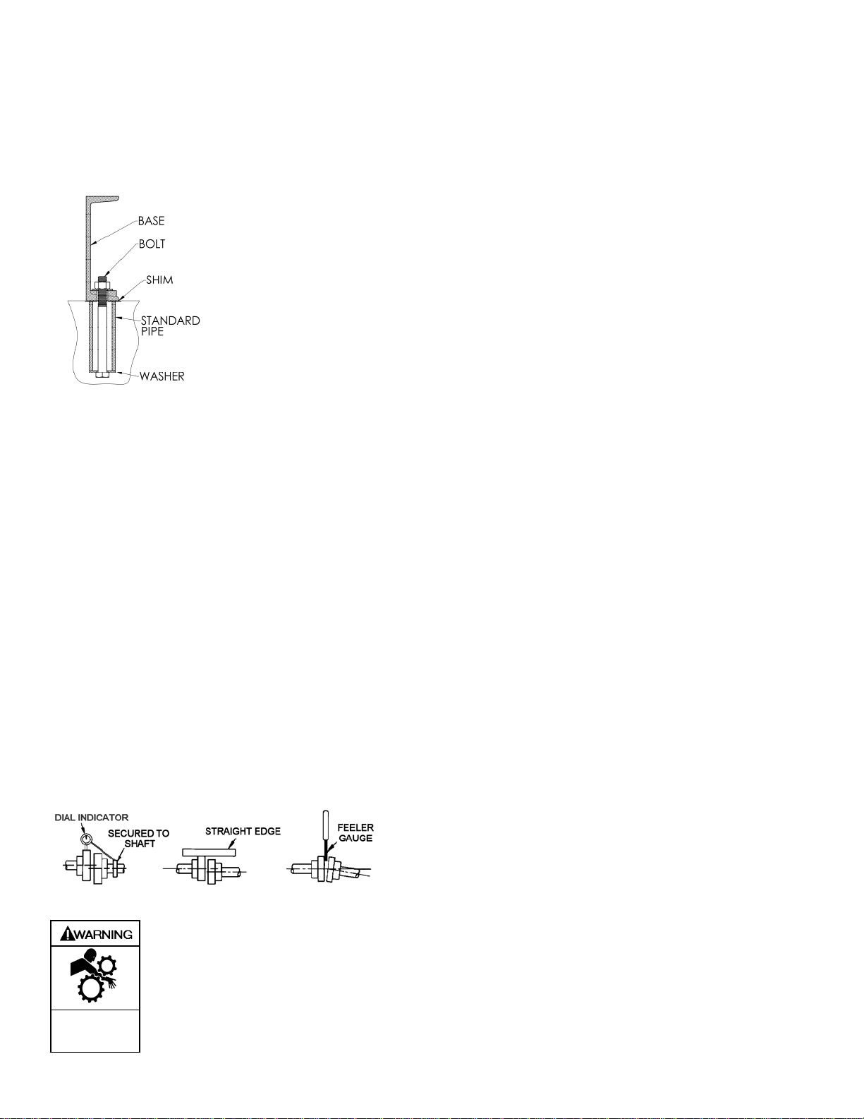
A solid foundation reduces noise and vibration, and will
improve pump performance. On permanent installations it is
recommended the pumping unit be secured by anchor bolts
as shown in Figure 2. This arrangement allows for slight
shifting of position to accommodate alignment with the
mounting holes in the base plate.
Figure 2 - Pipe Type Anchor
Bolt Box
For new foundations, it is
suggested that the anchor bolts
be set in concrete. When
pumps are to be located on
existing concrete floors, drill
holes into the concrete to hold
the anchor bolts.
When installing units built on channel or structural steel type
bases, use care to avoid twisting the base out of shape when
anchor bolts are tightened. Use shims under the edges of the
base prior to tightening the anchor bolts to level the base and
prevent distortion.
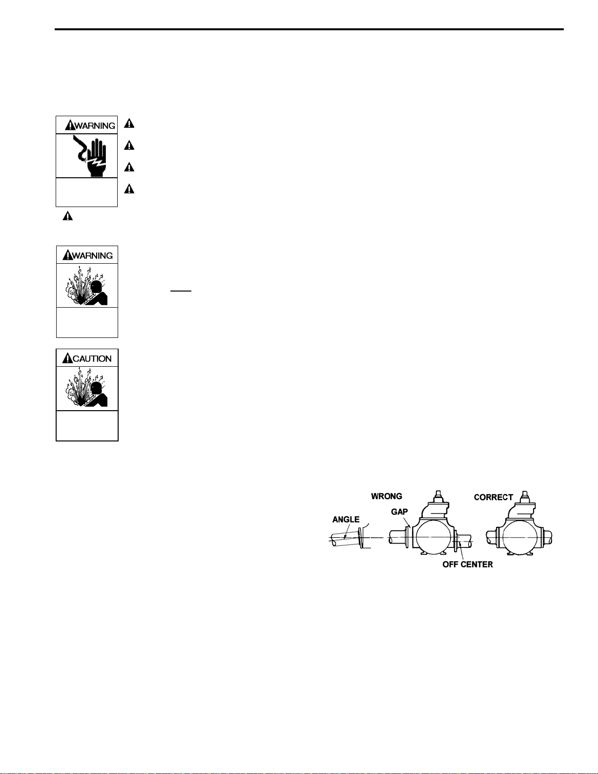
COUPLING ALIGNMENT
The pump must be directly coupled to a gear and/or driver
with a flexible coupling. Verify coupling alignment after
installation of new or rebuilt pumps. Both angular and
parallel coupling alignment MUST be maintained between the
pump, gear, motor, etc. in accordance with manufacturer’s
instructions. See Figure 3.
1. Parallel alignment: The use of a laser alignment tool or
dial indicator is preferred. If a laser alignment tool or dial
indicator is not available, use a straightedge. Turn both
shafts by hand, checking the reading through one
complete revolution. Maximum offset must be less than
.005" (.127 mm).
2. Angular alignment: Insert a feeler gauge between the
coupling halves. Check the spacing at 90° increments
around the coupling (four checkpoints). Maximum
variation must not exceed .005" (.127 mm). Some laser
alignment tools will check angular alignment as well.
3. Replace the coupling guards after setting alignment.
Figure 3 – Alignment Check
Do not operate
without guard
in place
Operation without guards in place can
cause serious personal injury, major
property damage, or death.
PUMP ROTATION NOTICE:
Confirm correct pump rotation by checking the pump
rotation arrows respective to piping flow direction. Do
not operate the pump in reverse rotation to reverse the
direction of flow.
1. Determine direction of flow where the pump will be
installed.
2. Confirm pump is installed in piping so that the flow will
pass through the pump from inlet to outlet. The inlet of
the pump has “INLET” cast in the cylinder and the outlet
has “OUTLET” cast in the cylinder.
3. Briefly “jog” pump with pump driver. Check rotation of
pump driver with respect to rotation arrow on pump.
A right-hand pump rotates clockwise with the intake on the
right side, when viewed from the driven end.
A left-hand pump rotates counterclockwise with the intake on
the left side, when viewed from the driven end.
TO CHANGE PUMP ROTATION
To reverse rotation, the pump must be disassembled then
reassembled with the shaft on the opposite side of the pump.
See the ‘Maintenance’ section for instructions.
CHECK VALVES
The use of check valves or foot valves in the supply tank is
not recommended with self-priming, positive displacement
pumps.
If the possibility of liquid backflow exists when the pump is
off, a check valve in the pump discharge piping is
recommended because the pump can motor in the reverse
rotation and create undue stress on all attached components.
Never start a pump when it is rotating in the reverse rotation
as the added starting torque can damage the pump and
related equipment. If a check valve is used, install it at the
pump discharge.
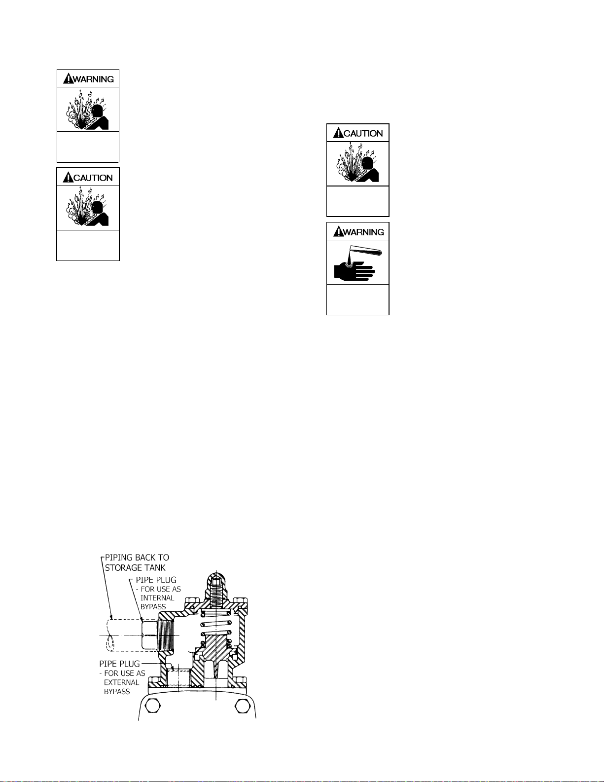
OPTIONAL JACKETED HEADS
Hot oil or steam can be circulated through jacketed heads by
connections at the jacket pipe plugs (73B) for heating highly
viscous liquids, or to "thaw out" liquids which have congealed
in the pumping chamber and packing area. Refer to the
'Technical Data' table on page 2 for the maximum allowable
steam pressure.
Make sure heat is applied early enough to sufficiently thin the
liquid before starting the pump. Liquids that congeal in the
relief valve chamber will make the valve inoperative.
Insulation of the pump with sufficient heat to the jackets will
usually thin the liquid in the relief valve chamber. Take
precautions to ensure the valve has free movement. It is
advisable to start the pump with an open discharge.
Drain the pump of all water when there is a possibility of
freezing. On models which have the steam connections on
the vertical center line, make the lower connection the outlet
so the water can be drained off. Models which have the
steam connections on the side also have a bottom drain plug.