TYPICAL AUTOMATED CLEANING CYCLE
At the beginning of the cleaning cycle, clean with DI water for a significant period of time before introducing any air at all
into the system. For example, the first thing the meter should see after push out is a relatively long blast of solvent or DI water
for at least 3 seconds or more depending on the coating. In the middle of the cleaning cycle, short (0.5 sec) air blasts will
maximize the scrubbing effect. At the end of the cleaning cycle, finish with solvent or DI water instead of air. The intention is
to put enough purge fluid into the system at this time to have the meter soaking in clean flush fluid at the end of the cycle.
When there are gaps in the line or when line stops occur after a color change, following this procedure will keep the meter
from potentially freezing up. In general, the meter should never see air for more than a few seconds and should never be
run dry.
OTE:N If new paint and purge fluid mixing is a problem, the fill cycle can start with a short 1 second shot of air to separate
the purge fluid and the paint.
During line shutdowns, such as overnight and over weekends, meters should be flushed and left filled with solvent, under
pressure, to allow any residue that may have built up to soak and dissolve. Filtration is recommended to prevent contaminants
from entering the meter. Should the meter become plugged, a reduced flow will still be observed from the nozzle or outlet as
fluid pressure will squeeze fluid through the meter. Should this occur, review the cleaning and maintenance procedures in the
following sections.
• Leave flushing solvent in the lines overnight or during extended off-times. This keeps internals wet, preventing residual
paint from drying and helping start ups.
• Follow the Maintenance Guide instructions when opening and cleaning a meter. During cleaning, separate the gears from
the shafts. On carbide bearings, clean inside the center of the gear bearing and on the outer surface of the shafts at the
point where the gear rotates on the shaft. Apply a suitable lubricating fluid before closing the meter. After tightening the
bolts, a short squirt of shop air will briefly spin the gears which should be easily audible.
• Install and maintain filters. The recommended filter should be installed to eliminate potential plugging. Should plugging
occur, the meter will still pass fluid but with no signal output.
• Check electrical compatibility between the meter’s output signal and the input of the PLC. If signals are not being
detected at start up, first check wiring and electrical compatibility.
• Verify reliable grounding of electrical parts, as per installation guidelines, and a dedicated power supply is recommended.
Voltage spikes on shared power lines, negligent grounding and sloppy wiring will likely produce erratic readings and
chronic maintenance. The control valve will provide back pressure which is beneficial to stable flow control.
• Install the meter immediately upstream of the regulator or control valve. The control valve provides back pressure which
stabilizes the flow.
• Do not allow air into the flow meter. Always keep the meter internally wet.
• Do not dry paint lines using pressurized air. Flow meters are designed to flow liquids. Meters should be closed to air except
when air is part of an automated purge cycle. Do not dry lines after purging.
• Do not allow materials to dry inside the meter. When a meter is removed from the line during maintenance, the internals
should be immediately cleaned, lubricated and the fluid ports capped.
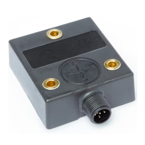
• Do not over tighten the pickup sensor beyond hand tight. When installing the pickup sensor, turn it in lightly to a hand
tight torque. Do not use a wrench on the pickup as over tightening may cause a dimple of metal under the sensor nose to
protrude into the gear cavity and interfere with the gear’s rotation.
• Do not use water or solvent for calibration or test purposes. Water or solvent may not turn the gears at low flow and may
leave the impression that the meter is not functioning. A calibration factor (K-factor) is issued with the flow meter which is
valid for most fluids except water or equivalent viscosities.
Typical Automated Cleaning Cycle
Page 6 February 2018PDM-UM-00274-EN-03


