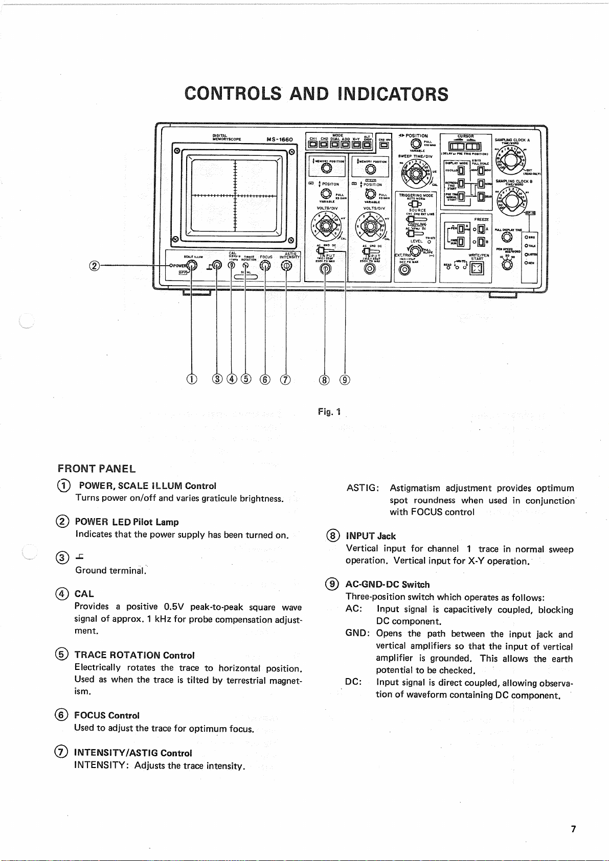
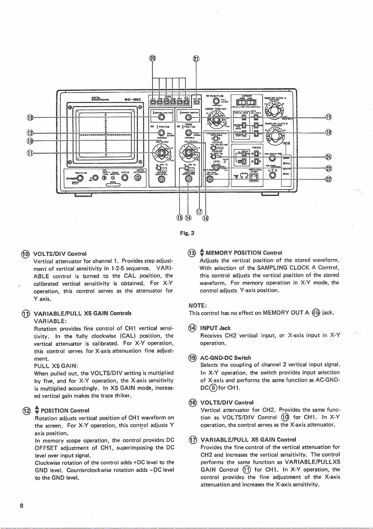
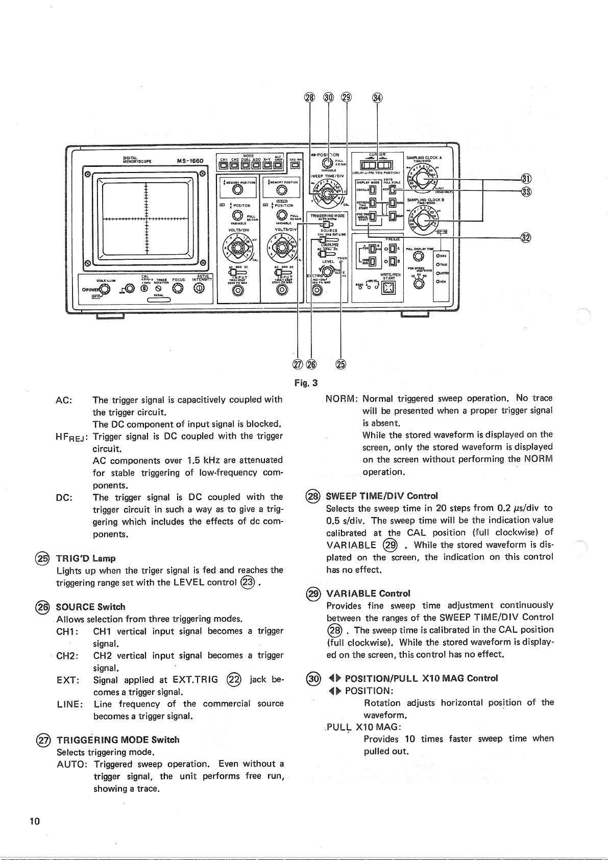
Kenwood MS-1660 User manual

MS-1660
(DIGITALMEMORY
SCOPE)
INSTRUCTION
MANUAL

SAFETY
Symbol
in
This
Manual
A
This
symbolindicateswhereapplicablecautionary
orotherinformationistobefound.
Power
Source
This
equipmentoperates
from
a powersourcethatdoes
notapplymorethan250V rmsbetweenthesupplycon-
ductorsorbetweeneithersupplyconductorandground.
A
protectivegroundconnectionbywayofthegrounding
conductorinthepowercordisessentialfor
safe
operation.
Grounding
theProduct
This
equipmentisgrounded
through
thegroundingcon-
ductorofthepowercord.Toavoidelectricalshock,plug
thepowercord
into
a properlywiredreceptaclebefore
connectingtotheequipment
input
or
output
terminals.
Use
theProperPowerCord
Use
onlythepowercordandconnectorspecifiedforyour
product.
Use
theProper
Fuse
To
avoidfirehazard,usea fuseofthecorrecttype.
DonotOperatein
Explosive
Atmospheres
To
avoidexplosion,donotoperatethisproductinanex-
plosive
atmosphere.
DonotRemoveCoverorPanel
To
avoidpersonalinjury,donotremovethecoverorpanel.
Refer
servicingtoqualifiedpersonnel.
VoltageConversion
Ifthepowersourceisnotappliedtoyourproduct,contact
yourdealer.Toavoidelectricalshock,donotperform
thevoltageconversion.
CONTENTS
SAFETY
2
FEATURES....
3
SPECIFICATIONS
4
PREPARATION
FORUSE6
CONTROLS
ANDINDICATORS7
FRONT
PANEL
7
REAR
PANEL
14
OPERATION
16
OPERATION
ASAN
OSCILLOSCOPE
16
(1)NORMAL
SWEEP
DISPLAY
OPERATION18
(2)MAGNIFIED
SWEEP
OPERATION
18
(3)
X-Y
OPERATION
18
MEMORY
SCOPE
OPERATION19
(1)WAVEFORM
OBSERVATION
19
(2)READINGTOPEN
RECORDER
21
(3)
CONTROLBY
GP-IB
21
APPLICATION
23
APPLICATION
ASAN
OSCILLOSCOPE
23
APPLICATION
ASA DIGITALMEMORY
SCOPE...
32
Power
InputVoltageConfiguration34
2

FEATURES
The
digital
memoryscopeMS-1660consistsofaDC-20MHz
bandwidth,dual-traceoscilloscope
with
a
built-in
digital
memory.Thememoryfeaturesa capacityof8 bitsx 2048
wordsperchannelanda maximumwritespeedof1
JUS/
word.The
unit
providestheabilitytostoreandreproduce
sporadic,
transientandrepetitiveevents,andrearthe
storedsignalsouttoa penrecorder,
through
simpleopera-
tion.
The
contentsofthememorycanbereadoutor
written
via
GP-IB
sothatexternaldatacanbemonitoredonthe
CRT
screenbystoringthedatainthememory.
Since
an
independentsamplingclockisprovidedforeach
channel,
separatesignalscanbestored
with
separate
clocks
atthesametime,andthesamesignalscanbe
storedata lowspeedanda highspeedatthesametime.
A
singletracecanbeusedas4Kwords.
1.
Foreachtrace,a memoryspaceof2kwordsispro-
vided.
The
unit
hastwoindependentsemiconductor
memoriesof8 bitsx 2048words
each.
2.
Dualchannel
Inputconsistsoftwoeventsata time,eachallotted
an
independentmemory
space.
Maximumwritespeed
is
1 jus/word.
3.
Dualclock
Two
completelyindependentsamplingclocksarepro-
videdtoallowsimultaneousstorageoftwo
totally
unrelatedsignals.Also,thesamesignalcanbestored
atlowspeedandhighspeed(equivalentofpartial
magnification)atthesametime.
4.
Minusdelayfunction
The
unit
iscapableofstoringthesignalsproduced
beforea triggerpulse,whicharenotobservableon
oscilloscopes.
The
dataafterthedelayset
point
canbeobservedon
theotherchannel,bymagnificationorcontraction.
The
delayset
point
iscontinuouslyvariable
with
cursor
indication.
5.
Hardcopy
The
penrecorderprovidedcanbeusedtoproducethe
hardcopyofthedisplayedwaveform
from
memory.
Inaddition,penfreerunfunctionisprovidedforauto-
matic
repetition
ofsignalstorageandcorresponding
hardcopyreproduction.
6.
Twostoragemodesareselectable.Therefreshmode
initiates
writing
with
a triggersignal.Inthepretrigger
mode,theterminationof
writing
iscontrolled
with
a
triggersignal,ineithermode,thewaveform
following
thecursor
point
canbeviewedinmagnifiedorcontract-
ed
form
intheotherchannel.
7.
Free
runfunctionforautomatic
repetition
ofread/write
operations
Once
written,thesignalsareheldina readstateforup
to20sec,thenentera writablestateinwhichthe
signals
waitfora triggersignal.
This
cycleisrepeated
automatically.
8.
Memorybackupfunction
Signals
storedremainunchangedinthememoryeven
after
turning
poweroff.
Thus
waveformsmaybe
ana-
lyzed
atanytimeonlater
days.
9.
Withthe
GP-IB
interface,thedata
within
inmemorycan
besentout,andexternaldatacanbe
written
inthe
memoryfordisplayonthe
screen.
10.
Linesynchronizationfacilitatestheobservationand
storageofthesignalsthataretriggered
with
theline
frequency.
11.
BysettingthemodetoX-Y,the
unit
changestoanX-Y
oscilloscope
with
a
one-button
operation.
12.
A rectangular,largesizedCRT
with
widerdisplay
area
providesfull-screensignalobservation.
13.
Thevertical
axis
providesa highsensitivityof1 mV/div,
plusa widebandrange
from
5mV/divtoa desiredset-
ting.
14.
The
unit
iscapableofhigh-speedsweepof20ns/div.
15.
A 150mmrectangularCRT
with
internalgraticule
(domedmeshtype,post-acceleration
with
6kVacceler-
ationvoltage)provides
easy
waveformobservation
without
parallax.
16.
The0,10,90,and100%marksonthescreenprovides
easy
measurementofrisetime.
17.
Theangleofhorizontaltracecanbeeasilycorrected
with
trace
rotation
controlsonthe
front
panel.
18.
The
scale
illuminationfacilitatesmeasurementina
darkplace,andalsoenablesphotographicrecording
oftheon-screenwaveform.
19.
Withtheautomaticfreerunfunction,thetracecanbe
checked
whilenosignalisfed.
20.
CH1
OUTPUT
terminalsareprovidedto
monitor
the
input
signalsontheCH1.
3

SPECIFICATIONS
4
CRT
Model:150
FTM31:
Rectangular,
with
internalgraticule
Acceleration
voltage:6 kV
Display
area:
8 X10div(1div= 10mm)
VERTICAL
AXIS(CommontoCH1andCH2)
Sensitivity:
1 mV/divto5V/div± 3%
Attenuator:5 mV/divto5V/div
1
-2-5
sequence,
fineadjust-
mentbetween10ranges
Inputimpedance:1 MSI ± 2%,Approx.25pF
Frequence
responce:
DC:
DCto20MHz(Within- 3 dB
at5 mV/divto5V/div)
DC
to10MHz(Within-3dB
atX5
GAIN)
AC:
5 Hzto20MHz(Within-3dB
at5 mV/divto5 V/div)
5
Hzto10MHz(Within-3dB
atX5
GAIN)
Rise
time
X1:
Less
than17.5ns
X5
GAIN:
Less
than35ns
Crosstalk:
Less
than-40dB(CH1& CH2
insamerange)
Operatingmodes:
CH1
CH1,
singletrace
CH2
CH2,singletrace
DUAL
CH1andCH2,dualtrace
ADD
CH1+ CH2(added)display
ALT
Dualorquadtracealternating
CHOP
Dualorquadtracechopped
X-Y
X-Yoscilloscope
CHOP
frequency:Approx.250kHz
Polarity
reversal:
AvailableforCH2only
Maximum
input
voltage:500Vp.por250V
(dc
+ acpeak)
Maximumundistorted
amplitude:8 div,minimum
(DC
to20MHz)
HORIZONTAL
AXIS(Channel2 input,exceptX10MAG)
Modes:
X-Ymodeisswitchselectable
CH1:
Yaxis
CH2:Xaxis
Sensitivity:
Same
asvertical
axis
(CH2)
Inputimpedance:
Same
asvertical
axis
(CH2)
Frequency
response:
DC:
DCto1 MHz(Within-3dB)
AC:
5 Hzto1 MHz(Within-3dB)
X-Y
phasedifference:
Less
than3°at100kHz
Maximumallowable
input
voltage:
Same
asvertical
axis
(CH2)
SWEEP
Sweep:
NORM;Triggersweep
AUTO;
Automaticfreerun
functionwhilesignalsarenot
fed
Sweep
time:0.2jus/div.to0.5s/div± 3%,
in1-2-5sequence
with
in20
ranges,
fineadjustmentbe-
tween20ranges
Sweep
magnification:X10± 5%
Linearity:
± 3%(0.2jus/div± 5%
with
X10
magnification)
TRIGGERING
CH1:
Triggered
with
vertical
input
signal
onCH1.
CH2:
Triggered
with
vertical
input
signal
onCH2.
EXT:
Triggered
with
external
synchronizing
signal.
LINE:
Triggered
with
linefrequency
External
triggering:
Inputimpedance:1 Mft± 2%,Approx.25pF
^Maximum
input
voltage:50V (DC+ ACpeak)
Couplingmodes:AC,
HFREJ
, DC
Sync
sensitivity
PROBE
CALIBRATING
VOLTAGE
0.5V
± 2%ofpositivesquare
wave,
approx.1 kHz
INTENSITY
MODULATION
Inputvoltage:Intensity
increases
with
TTL
level.
Inputimpedance:Approx.10kft
Frequency
range:DCto5 MHz
Maximum
input
voltage:50V (DC+ ACpeak)
VERTICAL
AXISCH1signal
output
OUTPUT
Outputvoltage:Approx.50mV/div(50ftload)
Outputimpedance:Approx.5012
Frequency
response:
X1:
100Hzto20MHz(within± 3
dB),
at50ft load
X5
GAIN:
100Hzto10MHz(within±3
dB),at
50ftload
SYNC
SYNC.
FREQ.
MIN.
SYNC
AMPLITUDE
(VOLTAGE)
COUPLING
RANGE
INT
EXT
DC DC
~ 20MHz
1
div 0-1vp.p
AC
10Hz
~ 20MHz
1
div 0-1vp.p
DC
HFREJ
At1.5kHzorover,min.amplitude(voltage)
requiredfor
sync
increases.

5
GATE
OUTPUT
Outputwaveform:Positivepulsetriggeredto
sweep
Outputvoltage:TTLlevel
Series
resistance:Approx.22012
DATA
CONVERTER
Convertingmethod:
Successive
comparison,
A/D
converter
Conversion
speed:1 jus/word
Resolution:
8 bits
(0.4%)
Frequency
response:DCto250kHz(within-3dB)
MEMORY
Memorycapacity:8 bitsX 2048words/CHX2
(Full
memorycapacityof4096
words)
Memorydevices:C-MOSstaticRAMs
Writespeed:1
Ms
to100ms/word,
with
1-2-5stepsin16ranges(with
independentchannelsetting)
Read
speed
INT:
MEMORYOUT:1 jus/word
(fixed)
SCOPE:
1 /is/word(fixed)
FOR
PEN:
10,20,50ms/word
(3
ranges)
EXT:
TTLlevel,repetitivesquare
wave
of
less
than1 MHz
High-levelpulsewidth;
Morethan500ns
Low-level
pulsewidth;
Morethan500ns
Rise
time;
Less
than500ns
FREEZE
function:Rewrite-protectableforeach
channel
Memorybackup:Fullmemoryholding.
Holdingtimeofmorethan200h.
OPERATING
FUNCTIONS
REFRESH
: Writeisstarted
with
thetrigger
(TRIG
START)
signal(ormanually).
Write
prohibition
variabletime
between1 to20sec
(DISPLAY
TIME)
PRE
TRIG:
A writeisstartedmanually.
(MANUAL
START)
Performspretriggeroperation
(negativedelay)accordingto
cursor
setting.Automatic,re-
peatedwrite/readoperations
are
available(readtimecanbe
DELAY:
set
from
approx.1 to20
sec).
address
issimultaneouslydis-
playedinotherchannel.
Cursor
settingCursoriscontinuouslymovable
within
addressesbetween2 and
2000
words.
Shiftingresolution1 word
(speed
variablein2 steps)
DATA
OUTPUT
D/Aconverter:
8-bit
resolution
Outputlevel:MEMORYOUT:1.6Vp-p± 3%
relativeto
input
full
scale
FOR
PEN:2.0Vp-p± 3%
relativeto
input
full
scale
(Over
1 k!2load)
Outputimpedance:MEMORYOUT:Approx.2212
CONTROL
OUTPUT
READ
GATE
OUT
Outputwaveform:Positivepulseequivalentto1
wordoflastaddress
Outputvoltage:TTLlevel(Commonto
both
channels)
Series
resistance:Approx.22012
READ
GATE
OUTFORPEN
ControlsignalforPEN
Outputsignal:Negativelogic(activatedabout
2
secafterpenstartON)
Outputvoltage:TTLlevel
Series
resistance:Approx.22012
EXTERNAL
CONTROL
The
datainmemoryiscontrollablevia
GP-IB.
Governingstandard:
IEEE
STD488-1978
Subsets
tobe
used:
SH1,
AH1,
TE0,
LEO,
T6,L4,
SR1,
RL1,
PP0,
DC1,andDT0
POWER
SOURCE
Line
voltage
100/120/220/240Vac
± 10%,
50/60Hz
Power
consumptionApprox.70W
DIMENSIONS
Width
426mm(433mm)
Height177mm(190mm)
Depth411mm(475mm)
Figures
in( ) includesproject-
ingparts.
WEIGHT
Approx.13kg
ENVIRONMENT
Operatingtemperatureand
humidity
forguaranteed
specifications:
10to35°C,85%RHmax.
Full
operatingtemperature
and
humidity
range:0 to45°C,85%RHmax.
ACCESSORIES
Probe
(PC-20)
2
Attenuation:1/10,1/1
Inputimpedance1/10:10M12,below18pF
1/1: 1 M12,below100pF
Instructionmanual:1
AC
powercord:1
Replacement
fuse:1
OPTION
GP-IB
cable
(CB-2420P)

PREPARATION
FORUSE
SAFETY
Before
connectingtheinstrumenttoa powersource,
carefully
readthe
following
information,thenverifythat
theproperpowercordisusedandtheproperlinefuseisin-
stalled
forpowersource.Thespecifiedvoltageisshownat
the
right
sideofthepowerconnectorontherearpanel.If
thepower-cordisnotappliedforspecifiedvoltage,thereis
always
a certainamountofdanger
from
electricshock.
Line
voltage
This
instrumentoperatesusingac-power
input
voltages
that100/120/220/240V atfrequencies
from
50Hzto
60
Hz.
Power
cord
The
groundwireofthe3-wireacpowerplug
places
the
chassis
andhousingofthememoryscopeatearthground.
Do
notattempttodefeatthegroundwireconnectionor
floatthememoryscopetodosomayposea greatsafety
hazard.
Theappropriatepowercordissuppliedbyan
option
thatisspecifiedwhentheinstrumentisordered.
The
optionalpowercordsareshownasfollowsin
Fig.
40.
Line
fuse
The
fuseholderislocatedontherearpanelandcontains
theline
fuse.
Verifythattheproperfuseisinstalledby
replacing
theline
fuse.
EQUIPMENT
PROTECTION
1.
Before
putting
thisinstrumentinuse,makesurethat
thepowersourceselectorswitchissettotheproper
positionthatcorrespondstothelinevoltage.Ifthe
selector
switchisnotproperlyset,this
causes
damage
totheinstrument.Connectthepowercordtothe
powerreceptacleonlyafterthisconfirmationismade.
2.
TheMS-1660shouldbeinstalledata placemeetingthe
following
conditions:
oTheMS-1660isnotexposedtodirectsunlight.
oTemperatureand
humidity
arenotveryhigh.Theair
does
notcontainmanydustparticles,
oThesurroundingfacilitiesandequipmentdonot
produceintensemechanicalvibration,magneticforce,
orimpulsevoltage.
3.
Neverapplymorethanthemaximumratedvoltageto
theoscilloscope
input
jacks.
CH1,
CH2
input
jacks:
500Vp-p
or250V(DC+
ACpeak)
AEXT
TRIG,
Z
AXIS
input
jacks:
50V
(DC+
ACpeak)
Never
applyexternalvoltagetotheoscilloscope
output
terminals.
4.
Whendesiringtoretainthestoredwaveformwhilethe
instrumentispoweredoff,pushthe
FREEZE
switch
before
turning
offthepower.
Keep
the
FREEZE
switch
pressed
whilethepoweristurnedoff.Itisdesirable
tokeepthe
FREEZE
switchpressedwhentheinstru-
mentispoweredonagaintoreproducethestored
wave-
form.Notethat,if
input
signalsourceisinconnection
with
theinstrumentwhenthepoweristurnedon,the
storedwaveformwillbe
erased
bythewriteoperation
started
with
an
input
signal.
The
upper3 bitsofthe
address
switchesfor
GP-IB
must
be
settothelowerpositions.
5.
Donot
increase
theintensitymorethanrequired.
6.
Neverallowa smallspotofhighbrilliancetoremainon
the
screen
forextendedperiodsoftime.
7.
WhenusingthisinstrumentinX-Ymode,setthe
PULL-
X10MAG
switchtothe
PUSH
position.Ifthisswitchis
set
tothe
PULL
position,thewaveformmaybedisturb-
ed
bynoise.
8.
Nevercovertheventilatingholesinthetopofthe
scope,
as
thiswill
increase
theoperatingtemperatureinsidethe
case.
9.
Whenremovingthe
case,
observethemaintenancein-
structioncontainedinthismanualtopreventa safety
hazard
because
thisinstrumentcontainshighvoltage
circuits.
10.
Always
groundtheinstrumentusingthe
FRAME
sideof
theGNDterminalsontherearpaneltopreventa safety
hazard.
11.
When
turning
onandoffthe
POWER
switchrepeatedly,
keep
anintervalofabout5
seconds.
Faster
onandoff
operationmay
cause
malfunctiontotheinstrument.
6

CONTROLS
ANDINDICATORS
Fig.
1
FRONT
PANEL
©POWER,
SCALE
ILLUMControl
Turns
power
on/off
andvariesgraticulebrightness.
©POWERLEDPilotLamp
Indicates
thatthepowersupplyhasbeenturnedon.
®J=
Groundterminal.
©CAL
Provides
a positive0.5Vpeak-to-peaksquarewave
signal
ofapprox.1 kHzforprobecompensationadjust-
ment.
©
TRACE
ROTATIONControl
Electrically
rotatesthetracetohorizontalposition.
Used
aswhenthetraceis
tilted
byterrestrialmagnet-
ism.
©
FOCUS
Control
Used
toadjustthetracefor
optimum
focus.
©INTENSITY/ASTIGControl
INTENSITY:
Adjuststhetraceintensity.
ASTIG:
Astigmatismadjustmentprovides
optimum
spotroundnesswhenusedinconjunction
with
FOCUS
control
©
INPUT
Jack
Vertical
input
forchannel1 traceinnormalsweep
operation.Vertical
input
forX-Yoperation.
©AC-GND-DCSwitch
Three-positionswitchwhichoperatesasfollows:
AC:
Inputsignaliscapacitivelycoupled,blocking
DC
component.
GND:
Opensthepathbetweenthe
input
jackand
verticalamplifierssothatthe
input
ofvertical
amplifierisgrounded.
This
allowstheearth
potentialtobechecked.
DC:
Inputsignalisdirectcoupled,allowingobserva-
tion
ofwaveformcontainingDCcomponent.
7

Fig.
2
@
VOLTS/DSV
Control
Vertical
attenuatorforchannel1.Providesstepadjust-
mentofverticalsensitivityin1-2-5sequence.
VARI-
ABLE
controlisturnedtotheCALposition,the
calibratedverticalsensitivityisobtained.ForX-Y
operation,thiscontrol
serves
astheattenuatorfor
Y
axis.
@
VARIABLE/PULL
X5GAINControls
VARIABLE:
RotationprovidesfinecontrolofCH1vertical
sensi-
tivity.
Inthefullyclockwise(CAL)position,the
verticalattenuatoriscalibrated.ForX-Yoperation,
thiscontrol
serves
for
X-axis
attenuationfineadjust-
ment.
PULL
X5
GAIN:
Whenpulledout,the
VOLTS/DIV
settingis
multiplied
byfive,andforX-Yoperation,the
X-axis
sensitivity
is
multiplied
accordingly.InX5GAINmode,increas-
edverticalgainmakesthetracethiker.
@y POSITIONControl
RotationadjustsverticalpositionofCH1waveformon
the
screen.
ForX-Yoperation,thiscontroladjustsY
axis
position.
Inmemoryscopeoperation,thecontrolprovidesDC
OFFSET
adjustmentofCH1,superimposingtheDC
level
over
input
signal.
Clockwise
rotation
ofthecontroladds+DCleveltothe
GND
level.Counterclockwise
rotation
adds-DClevel
totheGNDlevel.
@y MEMORYPOSITIONControl
Adjusts
theverticalpositionofthestoredwaveform.
Withselectionofthe
SAMPLING
CLOCK
A Control,
thiscontroladjuststheverticalpositionofthestored
waveform.FormemoryoperationinX-Ymode,the
controladjusts
Y-axis
position.
NOTE:
This
controlhasnoeffectonMEMORYOUTA @ jack.
@
INPUT
Jack
Receives
CH2vertical
input,
or
X-axis
input
inX-Y
operation.
©AC-GND-DCSwitch
Selects
thecouplingofchannel2 vertical
input
signal.
InX-Yoperation,theswitchprovides
input
selection
of
X-axis
andperformsthesamefunctionas
AC-GND-
DC®for
CH1.
@
VOLTS/DIVControl
Vertical
attenuatorforCH2.Providesthesamefunc-
tion
as
VOLTS/DIV
Control© forCH1.InX-Y
operation,thecontrol
serves
asthe
X-axis
attenuator.
@
VARIABLE/PULL
X5GAINControl
Provides
thefinecontroloftheverticalattenuationfor
CH2
andincreasestheverticalsensitivity.Thecontrol
performsthesamefunctionas
VARIABLE/PULLX5
GAIN
Control(R)forCH1.InX-Yoperation,the
controlprovidesthefineadjustmentofthe
X-axis
attenuationandincreasesthe
X-axis
sensitivity.
8

@
^ POSITIONControl
For
CH2,thecontrolprovidesthesamefunctionas
^
POSITION
Control@ forCH1.InX-Yopera-
tion,thecontrolprovides
X-axis
positionadjustment.
Inmemoryscopeoperation,thiscontrolprovidesDC
OFFSET
adjustmentforCH2.
@
^MEMORYPOSITIONControl
Withselectionofthe
SAMPLING
CLOCK
B control,
thiscontroladjuststheverticalpositionofthestored
waveform.FormemoryoperationinX-Ymode,the
controladjuststhe
X-axis
position.
NOTE:
This
controldoesnotworkforMEMORYOUTB @ jack.
@
MODESwitch
Selects
theoperationmodeofthevertical
axis.
CH1:
Onlythe
input
signaltochannel1 isdisplayed
onthe
screen.
Inmemoryoperation,a
differentdisplayisproducedonthescreen
accordingtotheselectionof
NORM/DELAY
selector
of
DISPLAY
MODE@ switches.
NORM:
Thewaveformstored
with
SAMPLING
CLOCK
A isdisplayedonthe
screen.
DELAY:The
waveformsstored
with
SAMPLING
CLOCK
A andB aredisplayedasdualtraces
onthe
screen.
CH2:
Onlythe
input
signaltochannel2 isdisplayed
onthe
screen.
Inmemoryoperation,a
dif-
ferentdisplayisproducedonthescreen
accordingtotheselectionof
NORM/DELAY
selector.
NORM:
Thewaveformstored
with
SAMPLING
CLOCK
B isdisplayedonthe
screen.
DELAY:
The
waveformsstored
with
SAMPLING
CLOCK
A andB aredisplayedasdualtraces
onthe
screen.
DUAL:
The
input
signalstochannel1 andchannel2
are
displayedonthe
screen.
Inmemory
operation,thewaveformsstored
with
SAMPL-
ING
COCK
A andB aredisplayedonthe
screen.
DELAY
operationwillnotbeproducedbut
onlyNORMoperationwillbeperformedeven
ifthe
NORM/DELAY
selectorissetto
DELAY.
ADD:
ThealgebraicsumofCH1andCH2signalsis
displayedonthe
screen.
WhentheCH2INV
21
button
isengaged,thedifferencebetween
CH1
andCH2signalsisdisplayed.
Inmemoryoperation,a differentdisplayis
producedaccordingtotheselectionof
NORM/DELAY
selector.
NORM:
Thescreendisplaysthewaveformwhichis
stored
with
SAMPLING
CLOCK
B asthe
ialgebraicsumofCH1andCH2signals(oras
thedifferencebetweenCH1andCH2signals
whenCH2INVisselected).
DELAY:
Thescreenprovidesa dualtracedisplaythe
wave
formswhicharestored
with
SAMPL-
ING
CLOCK
A andB asthealgebraicsumof
CH1
andCH2signals(orasthedifference
betweenCH1andCH2signalswhenCH2INV
is
selected).
X-Y:
TheinstrumentoperatesasanX-Yoscillo-
scope
with
CH1servingas
Y-axis
andCH2as
X-axis.
Inmemoryoperation,thewaveformstored
with
SAMPLING
CLOCK
A isdisplayedas
Y-axis
input,
andthewaveformstored
with
SAMPLING
CLOCK
B isdisplayedas
X-axis
input.
The
DELAY
operationwillnotbeproduced
butonlytheNORMoperationwillbepro-
ducedevenifthe
NORM/DELAY
selectoris
set
to
DELAY.
J-ALT/m
CHOP
Selector:
Selects
thedisplaymodefortwotracesinthe
DUAL
mode.
JL
ALT:CH1andCH2aignalsarealternatelydisplay-
ed.
m
CHOP:
CH1andCH2signalsaredisplayedbychop-
ping.
Inmemoryoperation,thealternatesweep
modeisautomaticallyselectedregardlessof
thesettingofthisselector.Settingtodisplay
thestoredwaveformonthe
screen.
NOTE:
Each
ofthemodesettingcontrolsisrelatedtothe
writing
into
memory.Seethedescriptionson
DISPLAY
MODE,
REFRESH/PRE
TRIG,
NORM/DELAY,
SAMPLING
CLOCK
A,B,and
CURSOR.
@
CH2INVButton
Inverts
thepolarityofCH2signal.
@
EXTTRIG
Jack
Whenthe
SOURCE
controlissettotheEXTposition,
thesweepistriggeredbythe
input
signalfed
through
thisjack.
@
LEVEL/PULL
SLOPE
(-)Control
LEVEL:
Adjuststhetriggerlevel,i.e.,the
point
onthe
triggersignalwaveformslopewherethesweep
starts.
PULL
SLOPE:
Adjusts
thepolarityofthetriggering.When
thecontrolispulledout,thetriggeroccurs
atthetrailingedgeofthe
input
waveform.
@
COUPLINGSwitch
Selects
thecouplingforthe
triggering
signal.
9

Fig.
3
AC:
The
trigger
signaliscapacitivelycoupled
with
the
trigger
circuit.
The
DCcomponentof
input
signalisblocked.
HFREJ:
TriggersignalisDCcoupled
with
the
trigger
circuit.
AC
componentsover1.5kHzareattenuated
forstable
triggering
oflow-frequencycom-
ponents.
DC:
The
trigger
signalisDCcoupled
with
the
trigger
circuitinsucha wayastogivea trig-
geringwhichincludestheeffectsofdccom-
ponents.
@
TRIG'DLamp
Lightsupwhenthe
triger
signalisfedandreachesthe
triggering
rangeset
with
the
LEVEL
control
(23).
@
SOURCE
Switch
Allowsselection
from
three
triggering
modes.
CH1:
CH1vertical
input
signalbecomesa
trigger
signal.
CH2:
CH2vertical
input
signalbecomesa
trigger
signal.
EXT:
Signalappliedat
EXT.TRIG
(22)jackbe-
comes
a
trigger
signal.
LINE:
Linefrequencyofthecommercialsource
becomesa
trigger
signal.
(27)TRIGGERINGMODESwitch
Selects
triggering
mode.
AUTO:
Triggeredsweepoperation.
Even
without
a
trigger
signal,the
unit
performsfreerun,
showinga trace.
NORM:
Normal
triggered
sweepoperation.Notrace
will
bepresentedwhena proper
trigger
signal
is
absent.
Whilethestoredwaveformisdisplayedonthe
screen,
onlythestoredwaveformisdisplayed
onthescreen
without
performing
theNORM
operation.
(28)
SWEEP
TIME/DIVControl
Selects
thesweep
time
in20steps
from
0.2/is/divto
0.5s/div.Thesweep
time
will
betheindicationvalue
calibratedattheCAL
position
(fullclockwise)of
VARIABLE
(2§). Whilethestoredwaveformisdis-
puted
onthe
screen,
theindicationonthis
control
has
noeffect.
@
VARIABLE
Control
Provides
finesweep
time
adjustmentcontinuously
betweentherangesofthe
SWEEP
TIME/DIV
Control
(28)
. Thesweep
time
iscalibratedintheCAL
position
(fullclockwise).Whilethestoredwaveformisdisplay-
edonthe
screen,
this
control
hasnoeffect.
(30)ikPOSITION/PULLXI0MAGControl
4k
POSITION:
Rotationadjustshorizontal
position
ofthe
waveform.
PULL
X10MAG:
Provides
10timesfastersweep
time
when
pulledout.
10

@)SAMPLING
CLOCK
A,B Controls
Select
a samplingfrequencyforthe
input
signalin
16
rangesbetween100msand1 jus/word.Between
the100msand1 jus/wordrange,thewaveformcanbe
observed
during
writeoperationbecausethe
input
signalisreadoutwhilethe
input
signalis
written
in
memory.Betweenthe50{is and1jus/wordrange,a
traceisdisplayed
during
writeoperationbecausethe
waveformisreadoutafterthewriteinthememory
(2
Kw)hascompleted.
Therefore,
whena continuous
trigger
waveformisfed,
theread
time
cannotbemaintained,producingdis-
continuedwaveformora traceonthe
screen,
butthe
waveform
will
bestorednormally.Whensucha
condition
ispresent,
pull
the
PULLDISPLAY
TIME
knob39tomaintainthereadtime.
Whenthe
DISPLAY
MODEselector@ issetto
NORM,
SAMPLING
CLOCK
A correspondstothe
CH1
input
signal,andthe
SAMPLING
CLOCK
B tothe
CH2
input
signal.Whenthe
DISPLAY
MODEselector
is
setto
DELAY,
SAMPLING
CLOCK
A andB cor-
respondtothe
input
signalofthemainchannelselect-
ed
with
theMODEselector@ . The
DELAY
posi-
tion
of
that
modeselectorcorrespondstoNORM.
Fully
clockwise
rotation
ofthe
SAMPLING
CLOCK
A
control
makesa connectiontothereadonlyEXT
CLOCK
terminals;consequently,thecontentsofthe
memoryarereadout
with
theclocksignal
that
isfed
from
theEXT
CLOCK
terminal@ ontherearpanel.
This
modeisusedonlyforreadoperationso
that
the
instrumentisfrozenformemoryprotection,
with
the
FREEZE
lampbeingon.Fullyclockwise
rotation
of
the
SAMPLING
CLOCK
B
control
providesconnection
with
GP-IB,
therebyallowingthereadingand
writing
ofmemorycontentsbyconnectingthe
GP-IB
control-
lertothe
unit.
(Fordetails,refertothedescriptionon
GP-IB.)
(32)
DISPLAY
MODESwitches
The
MS-1660operatesasa dual-traceoscilloscopeby
thepushof
OSCILLO
andasa memoryscopewhen
REFRESH
or
PRETRIG
isselected.
Combinationsofswitchsettingsallow
four
modesof
writing
input
signal
into
memory.
REFRESH-NORM:
A
writetomemoryisstartedbya
trigger
signalormanuallybythepushof
WRITE/
PEN
START
(37). After2048wordshave
beenwritten,thewriteoperationstops,and
the
unit
waitsinreadstateforthenext
trigger
signalormanualstart.
REFRESH-DELAY:
A
writetomemoryisstartedbya
trigger
signalormanuallybythepushof
WRITE/
PEN
START
(37)andcontinues
until
2048
wordshavebeenwritten.Thedataafterthe
cursor
point
(delaysetting
point)
aretransfer-
redtotheotherchannel:accordingtothe
samplingclockof
that
channel,thesedataare
written
by2048words
into
thememory
allocatedto
that
channel.Aftercompletion
of
writing
for
both
channels,the
unit
waitsin
readstateforthenext
trigger
signalormanual
start.
This
combinationprovidesthesamemodeas
REFRESH-NORM
whenMODE@)issetat
DUAL.
WhenMODE@)isatADD,thedata
following
thecursor
point
are
written
toCH1
accordingtothe
SAMPLING
CLOCK
A.
PRE
TRIG-NORM:
A
writetomemoryis
initiated
bypressing
WRITE/PEN
START
button
@ . The
point
set
by
CURSOR
switch(3^)becomesthe
memory's
trigger
address,andthewriteopera-
tion
continues
until
thenumberofwords
"(2K
words)— (wordsspecifiedbycursor
setting)"havebeen
written
after
input
of
trigger
signal.Thenthe
unit
waitsinroad
state
until
WRITE/PEN
START
@)isnext
pressed.
(PULL
DISPLAY
TIME
@)mustbe
OFF.)
This
modepermitsobservationofthe
waveformprecedingthe
trigger
signal.
WhenMODE@ issetat
DUAL,
CH1per-
formstheaboveoperation.CH2terminates
itswriteoperation
upon
completionofCH1
writeoperation.
PRE
TRIG-DELAY:
The
channelspecifiedbyMODE(20)per-
formsthesameoperationasinthePRE
TRIG-NORM
mode.Thedataafterthecursor
point
(delaysetting
point)
aretransferredto
theotherchannel;accordingtothesampling
clockof
that
channel,thesedataare
written
by2048words
into
thememoryallocatedto
that
channel.Afterdataare
written
for
both
channels,
the
unit
waitsinreadstateforthe
nextpushofthestart
button.
(PULL
DIS-
PLAY
TIME
6|mustbe
OFF.)
The
MODE@ issetat
DUAL,
CH1per-
formsthesameoperationasinthePRE
TRIG-NQRM
mode.CH2startsa writeto
memory
from
thecursor
point
(i.e.,
trigger
point
forCH1)andstopsthewriteoperation
when2048wordshavebeenwritten.
(33)8 DIV/4DIVSelector
Provides
a 1/1and1/2
output
levelsofthestored
waveformwhichisdisplayedonthescreenandtaken
attheMEMORYOUTjackontherearpanel.
With
this
button
notpressed,the
output
level
will
be
1.6Vp-p(at
full
input
scale).
With
this
button
pressed,
the
output
level
will
behalvedto0.8Vp-p(at
full
input
scale).
The
selectiondoesnotchangetheresolutionofthe
vertical
axis.
Therefore,
thewaveformsoftwoeventsarecon-
venientlyobservedbyselectingthe4DIVposition.
11

@
CURSOR
Switch
Displays
thebrightspot(cursorpoint)onthemain
channel
sideaccordingthecombinationsofsettingsof
MODE
(20)and
DISPLAY
MODE(32). Cursormove-
mentisintwo
speeds.
Thatis,whentherightorleft
button
ispressedonce,thecursorpointmovestothe
rightorleft,respectively,byoneword;holdingthe
rightorleft
button
depressedmovesthecursorcon-
tinuouslytothecorrespondingdirectionasfarasthe
button
is
depressed.
Thecursorpointwillstopupon
arrival
attherightorleftend.Thecursorpointis
movable
between2 and2000words(memory
address).
The
cursorpointdisplaymodeisavailabletothe
followingcombinations:
\Display
\mode
ModeV
REFRESH
PRE
TRIG
\Display
\mode
ModeV
NORM
DELAY
NORM
DELAY
cm -
Cursor
point
onCH1side
Cursor
point
onCH1side
Cursor
point
onCH1side
CH2 -
Cursor
point
onCH2side
Cursor
point
onCH2side
Cursor
point
onCH2side
DUAL
--
Cursor
point
onCH1side
Cursor
point
onCH1side
ADD -
Cursor
point
onCH2side
Cursor
point
onCH2side
Cursor
point
onCH2side
X-Y
- - - -
(35)
PEN/SCOPE,
FREE
RUN
Selectors
PEN/SCOPE:
Selects
the
output
directionofthememory
contents,
to
SCOPE
or
PEN.
Thereadspeed
varies
with
each
selection.
Pressing
the
button
sets
theunit
into
thePENmode(andthe
MEMORY
OUTterminalontherearpanel
willbeswitchedaccordingly).
When
thePENmodeis
selected,
press
PEN
START
@), andaftera preparatoryperiod
ofabouttwo
seconds,
thememorycontents
are
fedouttoFORPEN(46)atthespeedset
withPEN
SPEED
@ (10mst 50ms/word).
This
switchshouldnotbechangedtothePEN
modeduringa write.Ifsochanged,the
properwaveformmaynotbeobtained.
FREE
RUN:
This
modeautomaticallyrepeatsa writeto
memoryanda readtoFORPEN(^6).Asthe
writetomemory,controlledbya trigger
signal,
iscompleted,thePENmodeisauto-
matically
selected.
Then,
inabouttwo
seconds
ofpreparatoryperiod,signalsare
outputtedtoFORPEN(46), andaftercom-
pletionoftheoutput,theunitagainenters
thetriggerwaitstate.
NOTE:
The
properwaveformmaynotbeobtainedifthisswitchis
changed
tothe
FREE
RUNmodewhilethememorycon-
tentsarefedouttotheFORPENA,B
jacks
withPEN
START
button
inthePENmode.So,donotchangethe
settingofthisswitchduring
output
operation.
@FREEZE
button
Freezes,
i.e.,suspendsthewritethe
into
memory.
Pressing
theA sidestopsthewriteoperationonthe
memorywhichiscontrolledby
SAMPLING
CLOCK
A
(31), withtheresultthatthedatawillberetained
inthememory.
Pressing
theB sidestopsthewrite
operationonthecorrespondingmemory.Whenthis
switch
is
pressed,
thewriteA orB (38)lamplightsup,
indicatingthatthewriteoperationisapparentlyper-
formed,butthewriteoperationisactuallysuspended.
Withthepushofthe
FREEZE
switch,thegreenLED
ontheleftwill
light
up.
@
WRITE/PEN
START
Button
When
PEN/SCOPE
switch(35)issettothemonitor
mode,this
button
serves
asa manualstart
button
for
writetomemory.If
DISPLAY
MODE(32)issetto
REFRESH,
thepushofthis
botton
isinterpretedas
a
trigger
signal;
if
DISPLAY
MODE(32)issetto
PRE
TRIG,
thepushofthis
button
startsa writeto
memory,andaftercompletionofthewrite,theunit
enters
thetriggersignalwaitstate.
When
PEN/SCOPE
switch(35)issettothepenmode,
this
button
ispressedto
output
signalstoFORPEN
(^6).
Actually,thesignal
output
beginsabouttwo
seconds
afterthe
button
is
pressed.
@
WRITEA B,
READ
LEDs
These
LEDs
indicatewhethertheunitisinthe
WRITE
or
READ
state.Normally,directoryaftertheunit
is
poweredon,the
READ
(green)LEDlightsupto
indicatethe
READ
state.Whenthe
WRITE/PEN
START
(37)
button
ispressedorthewriteoperation
is
startedbya trigger
signal,
the
WRITE
A orB (red)
LED
lamplightsuptoindicatethewritestate.
(39)
PULL
DISPLAY
TIMEKnob
Afterbeingpulled,thisknobisturnedcounterclock-
wise
tomakethetimesettinglongerandclockwiseto
make
itshorter.Thetimecanbesetfromabout1 to
20
seconds.
Theunitperformsdifferentoperations
dependingonwhether
DISPLAY
MODE(32)issetat
REFRESH
or
PRETRIG.
REFRESH:
The
readtimeperiodaftera writeissetbythe
PULLDISPLAY
TIME
knobintherangeof
about1 to20
seconds.
Duringthisperiod,
theunitisinread-onlystate,thatis,a write
does
nottakeplace
because
anytiggersignal
is
ignored.Aftertheendofthesetperiod,
theunitentersthetriggerwaitstate,readyto
12

Fig.
execute
thenextwriteuponreceiptofa
triggersignal.
PRE
TRIG:
A
writetomemoryisstartednotbymanual
startbutattheintervalsetbythe
PULL
DISPLAY
TIME
knob.Uponreceiptofa
triggersignal,theunitperformsa PRE
TRIG
operation,andaftertheelapseoftheset
interval,
restartsa writetomemory.
If,inthismode,
WRITE/PENSTART
(37)is
pressed,
thewriteoperationmaystop.When
using
manualstart,therefore,ensurethatthe
PULLDISPLAY
TIME
button
is
OFF.
Inthe
event
ofanunwantedstopofwriteoperation,
thestopcanbecancelledbysimplypushing
an
thenpullingthe
PULLDISPLAY
TIME
button.
(40)PEN
SPEED
Selector
With
PEN/SCOPE
@ selectorsettothePENposition,
thisswitchbecomeseffectivetoselecta readspeedof
thePEN
output
in3
steps:
10,20,and50ms/word.
@
GP-IB
LEDs
The
four
LEDs
indicatethestateoftheunitwhenit
is
controlledbya
GP-IB.
Whenlit,eachLEDprovides
thefollowingindication:
SRQ:
Theunitisinservicerequestmode.
TALK:
Theunitisaddressedasthetalker.
LISTEN:
Theunitisaddressedasthelistener.
REN:
Theunitisinremotemode.
13

REAR
PANEL
Fig.
5
@
SWEEP
GATE
Jack
The
positive-pulsegatewaveformsynchronized
with
thesweepis
outputted
here.
(43)
Z AXISINPUT
Jack
External
intensity
modulation
input;
TTLcompatible.
Positive
voltage
increases
theintensity.
@
CH1OUTPUT
Jack
CH1
vertical
output
connector,
providing
a capacitively
coupledsignal.Usedasinfrequencymeasurementby
connectinga frequencycounter.
Cascade
connection
for
CH1
and
CH2
isnotallowed.
@
MEMORYOUTA,B
Jacks
The
dataforA andB storedintheirmemoriesare
taken
atthese
jacks
afterbeingconverted
into
analog
form.
When
theMODEswitchissettoADDandthe
DIS-
PLAY
MODEselectorissettoNORM,theadded
output
signalisfedonlytotheB jack.
@
FORPENA,B
Jacks
Output
(analog)signalconnectorsfora penrecorder.
The
datastoredbyusingthe
SAMPLING
CLOCK
A
control
isfedtotheA connector,andthedatastored
byusingthe
SAMPLING
CLOCK
B isfedtotheB
connector.
These
connectorsareonlyeffectiveinPEN
mode.
NOTE:
Itisimpossibletoseta PEN
SPEED
valueand
ON/OFF
state
foreitherjackindependentlyoftheother.
(47)
READ
GATE
OUT
Jack
The
positivepulsecorrespondingtotheonewordof
thelastaddressinthememoryisfedtothisconnector.
The
output
signal
from
thisconnectorcanbeusedasa
trigger
signalwhenreadingviatheEXT
CLOCK
connector.
@
READ
GATE
OUTFORPEN
Jack
This
connectorisusedto
control
a penrecorderor
otherdevice.
This
connectoriseffectiveinPENmode.
With
thePEN
START
button
pressed,
thesignalisfed
atlowlevel(TTL
level).
(49)EXT
CLOCK
Jack
External
clock
input
connectorforreadonly.
This
connectorisused
with
the
SAMPLING
CLOCK
A
switch
settoEXT.
(50)
GP-IB
Connector
When
connectingthisinstrumenttothe
GP-IB
inter-
face
thepiggybackcableisconnectedhere.Connec-
tion
ordisconnectionmustbedoneonlyafterthe
GP-IB
controllerispoweredoff.
14

(ST)GNDTerminal
The
groundterminalsfor
GP-IB
connection.Whenthe
shortbar(metal
fitting)
isconnectedbetweenthese
terminals,
theGNDlineinthe
GP-IB
connectorwillbe
groundedtothe
case.
(52)
ADDRESS
Selector
GP-IB
addresssettingswitch,representingaddressbits
1
through
5
from
the
right.
This
switchisusedtoset
the
GP-IB
address
with
fivebinarybits.
Each
bitbe-
comes
"1"
whenthecorrespondingswitchpositionis
set
totheupperside.Thethreeotherbitpositionson
the
left
mustbeheldonthelowerside.Ifanyofthese
threeisontheupperside,memorybackupwhenthe
powerisoffcannotbemade.
(53)FAN
Exhausts
airtocarrytheheatoutofthe
case.
(S)CordWrap
The
powercordiswrappedherewhenthe
unit
is
transportedorkeptinstorage.Thecordwrapsalso
serve
asthefeet.
(55)PowerConnector
The
powercordprovidedispluggedhere.
(56)VoltageSelector
Provides
a selectionofAClinevoltages100/120/220/
240
V byinsertionofanappropriateplug.
(57)
Fuse
Holder
Accommodates
a time-lagfuseof1 A for100/120V
supplyor0.5A 220/240Vsupply.
(58)Handle(BeltType)
Used
whentransportingthe
unit.
(59)Side
Legs
Useful
wheninstallingthe
unit
ina narrow
spaces
or
fortemporaryrestingduringtransport.
15

OPERATION
Before
turning
onthescope,setthe
front
panelcontrols
shownbelow.Fora detaileddescriptionofcontrols,see
"CONTROLS
AND
INDICATORS".
Whenusinga probe,refertoitsinstructionmanual,aswell
as
theparagraph
"PROBE
COMPENSATION"
under
"APPLICATION".
Fig.
6
OPERATIONASAN
OSCILLOSCOPE
[1]NORMALSWEEP'DISPLAYOPERATION
1.
Turnthe
POWER
switch(T)clockwise— thepower
supply
will
beturnedonandthe
pilot
lamp
will
light.
Set
thesemodesasfollows:
VerticalMODE@ : CH1
TRIGGERING
MODE@ : AUTO
DISPLAY
MODE@ :
OSCILLO
2.
ThetraceshouldappearinthecenteroftheCRTdis-
play.Ifnot,centerit
with
POSITION
@.Next,
adjustthe
INTENSITY
©and,if
necessary,
the
FOCUS
(1T)for
ease
ofobservation.
3.
Applyan
input
signaltochannelCH1INPUTjack@
andadjust
VOLTS/DIV
@fora suitable
size
displayof
thewaveform.
WhenMODEswitch@ issettoCH2andan
input
signalisappliedtoCH2INPUT@ aswell,the
input
signalforCH2isdisplayedonthescreen
through
opera-
tionssimilartoCH1.
WhenMODE@)issettoADD,thescreendisplaysthe
waveformrepresentingthealgebraicsumofCH1+ CH2.
IfCH2INV(2?)isthenpressed,thedisplaychangesto
thealgebraicdifferenceofCH1- CH2.
The
sensitivity
will
bethevalueof
VOLTS/DIV
setting
if
both
channelsaresettothesame
VOLTS/DIV
setting.
WhenMODE(20)issettoDUALorALT,thesweep
alternatesbetweenCH1andCH2.
4.
Ifthewaveformtobedisplayedcannotbe
triggered
or
the
trigger
point
istobeshifted,
follow
the
triggering
instructionsgivenbelow.
TRIGGERING
For
thewaveformof
input
signaltobeobserved,itmustbe
heldstationarybyproperly
triggering
thesweepcircuit.
Triggermaybeinternalwherethecircuitis
triggered
bythe
input
waveformtobeobserved,oritmaybeexternal
wherea signalhavinga certaintime-relationship
with
the
input
signalisappliedtotheexternal
trigger
terminal.
(1)
Theselectionofa signal
that
serves
asthe
trigger
signalismadeusingthe
SOURCE
selector.Inobser-
vationofsomewaveform,theDCcomponentor
high-frequencycomponentsuchasnoisemaynotbe
requiredasthe
trigger
signal.Therefore,the
COUPL-
ING
control
shouldbeadjustedtothespecific
pur-
poses.
16

INTERNAL
TRIGGERING
By
setting
SOURCE
selector@ toCH1,CH2,or
LINE,
the
input
signalinthe
triggering
circuitisconnectedtothe
internal
trigger
source.
Any
input
signalcanbeeasilytriggered,becausethe
input
signalfedtoINPUT®or(M)isbranchedinthevertical
amplifiertothe
trigger
circuitso
that
itactstocreate
trigger
signalsynchronized
with
the
input
signal,thusdriv-
ingthesweepcircuit.
With
the
SOURCE
selectorsettoCH1orCH2,a
trigger
is
developpedbytheCH1orCH2signalregardlessofthe
MODE
setting.
With
the
SOURCE
selectorsetto
LINE,
triggering
isdelivered
from
thecommerciallinefrequency.
EXTERNAL
TRIGGERING
With
the
SOURCE
selectorsettoEXT,a
trigger
signal
appliedtotheEXT
TRIG
jack(2^)
serves
astheexternal
trigger.
External
triggering
shouldbeusedwhena signal
different
from
the
input
signalforthevertical
axis
isused
fortriggering.Inthis
case,
the
trigger
signalmusthavea
certain
time
relation
with
thevertical
input
signal.
Fig.
7 shows
input
and
output
signalsobservedwhena gate
signalisfedtoEXT
TRIG
jack(2^)asa
trigger
signal(the
sweep
circuitisdriven
with
thegatesignal)and,atthe
same
time,theburstsignalproducedbythegatesignal
is
fedtothesamplecircuit.
As
showninthefigure,external
triggering
producesthe
proper
trigger
regardlessofthe
input
signalto
INPUT
jacks
(1f)and
(14).
Thus
thereisnoneedof
triggering
adjustment
even
ifthe
input
signal
varies.
Trigger
signal
(Gate
signal)
CH1
(Inputsignalof
amplifier,etc.)
CH2
(Outputsignalof
amplifier,etc)
(2)
Settingofcouplingswitch
AC
The
trigger
signaliscapacitivelycoupled,soitsDC
componentiscut,givinga stable
trigger
whichisnot
affectedbytheDCcomponent.
With
thisadvantage,
this
position
ofthecouplingswitchisconveniently
selected
forordinaryapplications.However,ifthe
trigger
signalislowerthan10Hz,the
trigger
signal
level
becomesattenuated,resultingin
difficulty
in
triggering.
HFREJ
The
trigger
signalissupplied
through
a low-pass
filter
toeliminatethehigh-frequencycomponent(higher
than1.5kHz),givinga stable
triggering
with
low-
frequencycomponent.Whenhigh-frequencynoiseis
superimposedoverthe
trigger
signalasshownin
Fig.8,
thehigh-frequencynoiseiscuttoprovidea stable
trigger.
Waveform
withhigh-frequencynoisesuperimposed
DC
The
trigger
signalandthe
trigger
circuitaredirectly
coupledtoallow
triggering
from
DCcomponents.
This
modeisuseful
I
forthe
triggering
with
a low-frequency
waveformbelow10Hzor
with
a slowlyrepetitive,
sharp
edgesignalsuchaslampwaveform.
(3)
Afterthe
SOURCE
hasbeenset,the
trigger
point
can
besetby
rotating
LEVEL/SLOPE
control
@.
TRIGGER
LEVEL
The
trigger
point
ofwaveformisset
with
the
LEVEL
and
SLOPE
controls.Fig.9 showstherelationbetween
LEVEL
and
SLOPE
with
respectto
trigger
point.
Setthelevelof
the
trigger
point
asrequired.
+
Direction
LEVEL
Fig.
9
17
Trigger
signal
processed
in
HFp^j
mode
Fig.
8
"-"rangeof
SLOPE
"+"
rangeof
SLOPE
-Direction

AUTO
TRIGGER
.
With
the
TRIGGERING
MODEselector(27)setto
AUTO,
thesweepcircuitissetinthefreerunmodewhilethe
trigger
signalisnotpresent.So,auto
triggering
isuseful
forGNDlevelconfirmation.
When
trigger
signalisfed,the
trigger
point
canbesetby
usingthe
LEVEL
and
SLOPE
controlsasinthe
case
of
normaltriggering.Whenthe
trigger
point
exceedsthe
trigger
range,the
unit
entersthefreerunmodeandthe
waveform
will
flow.
Normally(with
TRIGGERING
MODEsettoNORM),
whenno
trigger
signalispresentorthe
trigger
rangeis
exceeded,
thesweepisdeactivatedandnotraceisgenerat-
ed.
5.
Adjustthe
SWEEP
TIME/DIV
control
@ togivea
suitabledisplay.
Adjustthe
VARIABLE
control
@ asrequired.By
doing
this,normalsweepdisplayisproduced.
[2]MAGNIFIED
SWEEP
OPERATION
Since
merelyshorteningthesweep
time
tomagnifya
por-
tion
ofthewaveformonthescreencanresultinthedesired
portion
disappearingoffthe
screen,
suchmagnifieddis-
playshouldbeperformedusingthemagnifiedsweep.
Procedure:
Usingthe
POSITION
control
@,adjustthedesired
portion
ofwaveformtothecenteroftheCRT.Thenthis
control
canbepulledouttomagnifythedisplay10times.
For
thistypeofdisplaythesweep
time
isthe
SWEEP
TIME/DIV
settingdividedby10.
[3]X-YOPERATION
Phase
differencemeasurementsmaybemadebyuseofthe
X-Y
displaymode.
Procedure:
Set
theMODEswitch@ toX-Y.Inthismodethechannel
1
orY
input
becomesthe
Y-axis
input,
andthechannel2 or
X
input
the
X-axis
input
forX-Ydisplay.
The
vertical
position
isadjusted
with
*
POSITION
@of
CH1,
andthehorizontal
position
is
with
^
POSITION
(TS)
ofCH2.
X
andY sensitivityaresetbyusingthechannel2 and
channel1
VARIABLE
and
VOLTS/DIV
controlsre-
spectively.
18

MEMORY
SCOPE
OPERATION
[1]
WAVEFORM
OBSERVATION
Set
each
controltodisplaythewaveformasinthe
case
of
an
ordinaryoscilloscope.
(1)
Set
each
controlasfollows:
MEMORY
POSITION
: Center
PULLDISPLAY
TIME
: OFF
FREEZE
: OFF
PEN/SCOPE
:
SCOPE
(2)
Set
SAMPLING
CLOCK
sothatitcorrespondstothe
inputfrequency.(Ifthe
SAMPLE
CLOCK
settingis
lower
thantheinputfrequency,analiasingerror
occurs).
(3)
Set
DISPLAY
MODE
to
REFRESH
orPRE
TRIG.
REFRESH
mode:
When
a signalisfedtothe
INPUT
connectoronthisunit
and
exceeds
thetriggerlevelsetting,the
WRITE
LED
lamps
A,B will
light
uptoindicatethatthewriteopera-
tion
isbeingperformed.
These
LEDlampsrelateto
SAMPLING
CLOCK
A andB;
theirlightingtime
varies
withthesettingrange(thetime
consumed
forwritingoneword
into
memory)ofthe
SAMPLING
CLOCKs.
When
SAMPLING
CLOCK
issettoa
CLOCK
position
which
isslowerthan0.1ms/wordwhilethe
WRITE
LED
lightsandthewriteoperationisperformed,thewriteand
read
operationsaresimultaneouslyperformed.Onthe
screen,
theinput
signals
appearsequentiallyfromtheleft.
When
SAMPLING
CLOCK
issettoa
CLOCK
position
faster
than0.1ms/word,the
signals
disappearjustfor
moment
(less
thanapprox.100ms)duringwriteoperation,
butthewaveformisdisplayedinanalmoststablecondi-
tion
because
thewriteoperationwillbeinstantlycom-
pletedandthereadoperationwillbeimmediatelystarted.
If
theinputsignalisa continuouswaveformwithshorter
period
(sine
wave,
triangular
wave,
rectangular
wave,
etc.),
thewriteoperationisrestartedbythenexttriggerpulse
immediatelyafterthewriteoperationiscompleted.
There-
fore,
ifthe
SAMPLING
CLOCK
issettoa
CLOCK
posi-
tion
fasterthan0.1ms/word,thewriteandreadopera-
tionsarecyclicallyperformed,withtheresultthatthe
trace
duringthewriteoperationmayappearonthe
screen,
producingflicker.Iftoobservethewaveformin
such
a
condition,performthefollowingadjustment:
By
pullingthe
PULLDISPLAY
TIME
controlandturning
it
clockwise,
therestarttimecanbechangedbycontrolling
the
successive
trigger
pulses.
Fully
clockwiserotationof
thecontrol
disables
thenextwriteoperationforabout20
seconds,
maintainingthereadstate(theadjustmentis
variable
betweenapprox.1 to20
seconds.)
PRE
TRIG
mode
This
modeprovidesthe
PRE
TRIG
(-
DELAY)
operation
which
ispreculiartothedigitalmemory
scope.
In
thismode,writeoperationisusuallystartedmanually
(by
pressingthe
WRITE
START
button).
Writeoperationcan
also
bestartedrepeatedlyatregular
timeintervalsbyusingthe
PULLDISPLAY
TIME
control.
If
thesignalappliedtotheunitisnota continuous
wave
butissporadic,thetracedevelopsa flickeringbrightspot
onitsleftend.Thepositionofthebrightspotisthe
guidepointthatrepresentsthetriggerpointafterwrite
(i.e.,
the
address
positiononthe
screen).
Thebrightspot
is
movedtotherightorleftbypressingthe
CURSOR
switch.
When
thewaveformpriortothetriggerpointistobe
dis-
played
onthelefthaldofthe
screen,
press
the
CURSOR
switch
untilthebrightspotispositionedtothecenterof
the
screen.
Afterthispositioning,thepushofthe
WRITE
START
button
(manualstartinthis
case)
causes
lighting
oftheLEDof
WRITE
A orB (dependingon
MODE
switch
setting),
whichindicatesthewritingoperatingisbeing
performed.
ThelightingoftheLEDisindependentofthe
input
signal.
Iftheinputsignalcomesto
exceed
the
TRIG
LEVEL
setting,asindicatedbylightingofthe
TRIG'D
lamp,
thewritingoperationisterminatedafterwritingof
thefollowinginputwaveform,andthe
WRITE
A,B
LEDs
gooff.Uponthisterminationofwriting,thetriggerpoint
forthewaveformjuststoredmovestothebrightspot
positionedwiththe
CURSOR
switch.Theunitisthenheld
inreadstate,witha stillwaveformonthe
screen.
The
result
isthatthewaveformbeforethetriggerpointis
dis-
played
totheleftofthebrightspotonthe
screen,
andthe
waveform
afterthetriggerpointistotherightofthebright
spot.
Given
beloware
examples
of
output
waveformobtainedin
various
modes.
(1)
DISPLAY
MODE:
REFRESH-NORM
1
MODE:
CH1orCH2
Waveform
ofCH1orCH2
inputsignal(controlled
by
SAMPLING
CLOCK
A
orB)
Waveform
ofCH1input
signal
(controlledby
SAMPLING
CLOCK
A)
Waveform
ofCH2input
signal
(controlledby
SAMPLING
CLOCK
B)
CH1
andCH2input
signals
are
same,
but
SAMPLING
CLOCK
A
is
settotwicethe
SAMPLING
CLOCK
B setting.
19
Trigger
point
•2048W-
(2)
MODE:
DUAL
-2048W
Trigger
point

3
MODE:
ADD
(4)
DISPLAY
MODE:
PRETRIG-DELAY
1
MODE:
CH1
or
CH2
Synthesized
waveformof
CH1
andCH2inputsignals
(controlledby
SAMPLING
CLOCK
B)
(2)
DISPLAY
MODE:
REFRESH-DELAY
1
MODE:
CH1
or
CH2
Waveform
ofCH1orCH2
inputsignal(controlledby
SAMPLING
CLOCK
A or
B)
•
WaveformofCH1orCH2
inputsignal(controlled
by
SAMPLING
CLOCK
B
orA)
SAMPLING
CLOCK
A (orB)issettotwicethe
SAMPLING
CLOCK
B (orA)setting.
3
MODE:
ADD
Trigger
point
Synthesized
waveformCH1
and
CH2inputsignals
(controlledby
SAMPLING
CLOCK
A)
Synthesized
waveofCH1
and
CH2inputsignals
(controlledby
SAMPLING
CLOCK
B)
SAMPLING
CLOCK
B issettwicethe
SAMPLING
CLOCK
A
setting.
Waveform
ofCH1orCH2
inputsignal(controlledby
SAMPLING
CLOCK
A or
B)
2
MODE:
DUAL
Synthesized
waveformof
CH1
andCH2inputsignals
(controlledby
SAMPLING
CLOCK
B)
Waveform
ofCH1orCH2
inputsigna(controlledby
SAMPLING
CLOCK
A or
B)
Waveform
ofCH1orCH2
inputsignal(controlledby
SAMPLING
CLOCK
B or
A)
SAMPLING
CLOCK
A (orB)issettotwicethe
SAMPLING
CLOCK
B (orA)setting.
Waveformbeforetrigger
Waveform
ofCH1input
signal
(controlledby
SAMPLING
CLOCK
A)
Waveform
ofCH2input
signal
(controlledby
SAMPLING
CLOCK
B)
CH1
andCH2inputsignalsare
same,
but
SAMPLING
CLOCK
A
is
settotwicethe
SAMPLING
CLOCK
B setting.
Synthesized
waveformof
CH1
andCH2inputsignals
(controlledby
SAMPLING
CLOCK
A)
Synthesized
waveformof
CH1
andCH2inputsignals
(controlledby
SAMPLING
CLOCK
B)
SAMPLING
CLOCK
B issettotwicethe
SAMPLING
CLOCK
A
setting.
20
Trigger
point
2048W
2048W
Cursor
point
Trigger
point
2048W
Waveformbeforetrigger
Trigger
point
=
cursor
point
2
MODE:
DUAL
•2048W-
Trigger
point
=
cursor
point
2
MODE:
DUAL
Same
operationasin
DUAL
modeof
REFRESH-NORM
mode.
3
MODE:
ADD
-2048W-
Cursor
point
2048W
Waveformbeforetrigger
;
Triggerpoint
!
=
cursor
point'
Fig.
10
(3)
DISPLAY
MODE:
PRE
TRIG-NORM
1
MODE:
CH1
or
CH2
-2048W
Waveformbeforetrigger
Trigger
point
=
cursor
point
2048W-
Waveformbeforetrigger
Trigger
point
=
cursor
point
End
pointof
CH1
input
write
Waveform
ofCH1input
signal
(controlledby
SAMPLING
CLOCK
A)
Waveform
ofCH2input•
signal
(controlledby
SAMPLING
CLOCK
B)
CH1
andCH2inputsignalsare
same,
but
SAMPLING
CLOCK
A
is
settotwicethe
SAMPLING
CLOCK
B setting.
2048W
Waveformbeforetrigger
Trigger
point
=
cursor
point
Table of contents
Other Kenwood Measuring Instrument manuals

Kenwood
Kenwood FL-140 User manual

Kenwood
Kenwood VT-172 User manual

Kenwood
Kenwood HM-250 User manual

Kenwood
Kenwood FC-757 User manual

Kenwood
Kenwood VT-176 User manual

Kenwood
Kenwood VT-175 User manual

Kenwood
Kenwood VT-171 User manual

Kenwood
Kenwood VT-181 User manual

Kenwood
Kenwood FL-180 User manual

Kenwood
Kenwood FC-758 User manual