3
Contents
INTRODUCTION....................................................................................................................................... 2
CHAPTER 1 - OVERVIEW .......................................................................................................................... 4
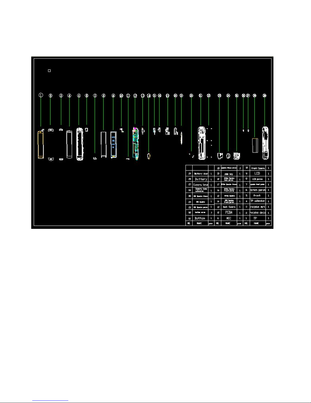
EXPLODED VIEW AND COMPONENT DISPOSAL EXPLODED....................................................................................................4
DISASSEMBLY AND ASSEMBLY SERVICE TOOLS .....................................................................................................................5
CHAPTER 2 –SYSTEM BLOCK DIAGRAM ................................................................................................... 7
CHAPTER 3 –UNIT CIRCUITRY.................................................................................................................. 8
CPU CIRCUIT............................................................................................................................................................................8
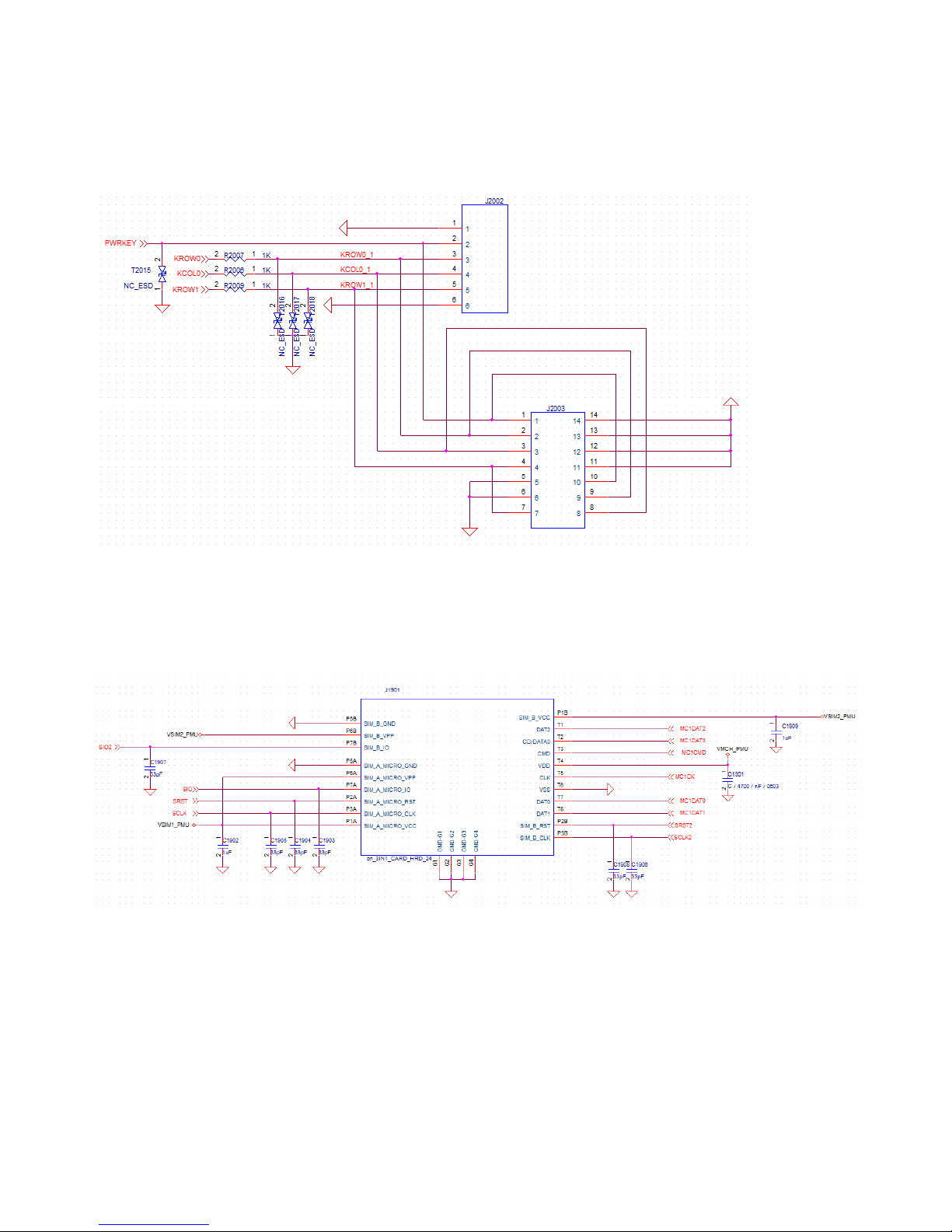
CPU - KEYPAD INPUT............................................................................................................................................................10
SIM 1, SIM 2, T-FLASH JOINT CIRCUIT..................................................................................................................................10
EMMC - MCP ........................................................................................................................................................................11
BLUETOOTH/WIFI/GPS/FM..................................................................................................................................................12
MT6323 CPU POWER SUPPLY PORT.....................................................................................................................................14
BATTERY CONNECTOR ..........................................................................................................................................................16
CHARGER CIRCUIT ................................................................................................................................................................16
I/O CONNECTOR (5PIN).........................................................................................................................................................17
RF IC MT6166........................................................................................................................................................................17
WCDMA RF ...........................................................................................................................................................................19
AUDIO...................................................................................................................................................................................20
LCD INTERFACE .....................................................................................................................................................................23
LCD BACKLIGHT ....................................................................................................................................................................24
CAMERA INTERFACE.............................................................................................................................................................24
G-SENSOR .............................................................................................................................................................................25
ALS & PS SENSOR .................................................................................................................................................................25
TOUCH PANEL .......................................................................................................................................................................26
CHAPTER 4 - PCBA................................................................................................................................. 26
PCB LAYOUT CHART ..............................................................................................................................................................26
PCB SIDE A ............................................................................................................................................................................26
PCB SIDE B.............................................................................................................................................................................27
CHAPTER 5 - TROUBLESHOOTING .......................................................................................................... 31
TEST FLOW CHART OF TEST SIM CARD .................................................................................................................................31
TEST FLOW CHART NO POWER ON (MAIN).........................................................................................................................32
TEST FLOW CHART HEADPHONES........................................................................................................................................33
TEST FLOW CHART LCD.........................................................................................................................................................34
TEST FLOW CHART DOWNLOAD FAILED ..............................................................................................................................35
CHAPTER 6 –SOFTWARE UPDATE .......................................................................................................... 36
INSTRUCTION OF SW UPDATE..............................................................................................................................................36
CHAPTER 7 –FUNCTION TEST ................................................................................................................ 41
FUNCTION TEST ....................................................................................................................................................................41
CHAPTER 8 –PARAMETER SETTINGS...................................................................................................... 42