Blu Studio 5.0 II User manual

Customer Service Service Manual
1/ 44
BLU STUDIO 5.0 II
SERVICE MANUAL

Customer Service Service Manual
2/ 44
CAUTIONS
Please refer to the phone’s user’s guide for instructions relating to operation, care, and maintenance, which include
important safety information.
Servicing and alignment must be undertaken by qualified personnel only.
Ensure all work is carried out at an anti-static workstation and that an anti-static wrist strap is worn.
Use only approved components as specified in the parts list.
Ensure all components, modules, screws, and insulators are correctly re-fitted after servicing and alignment
Ensure all cables and wires are repositioned correctly
Electrostatic discharge can easily damage the sensitive components of electronic products. Therefore, every service
supplier must observe the precautions which mentioned above.
CONTENTS
Content
1. Brief Introduction….……………………………………………………………………………….….3
2. Tools……………………………………………………………………………………………………..5
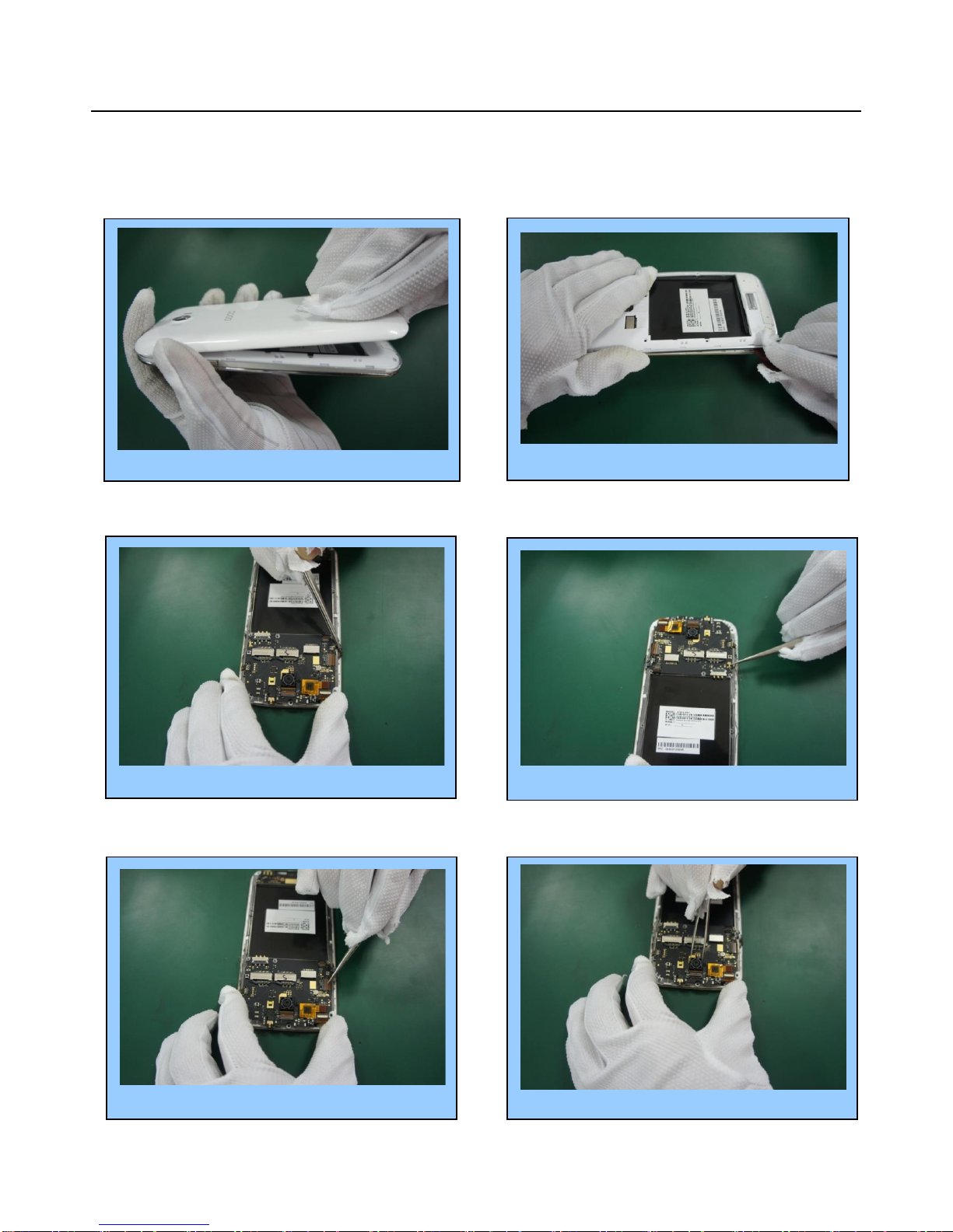
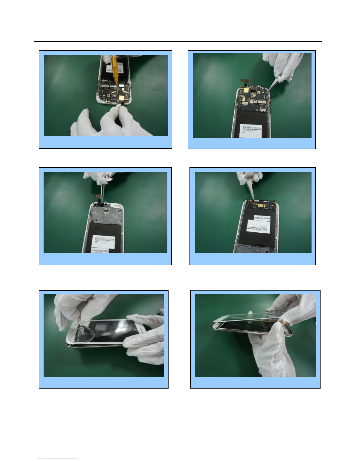
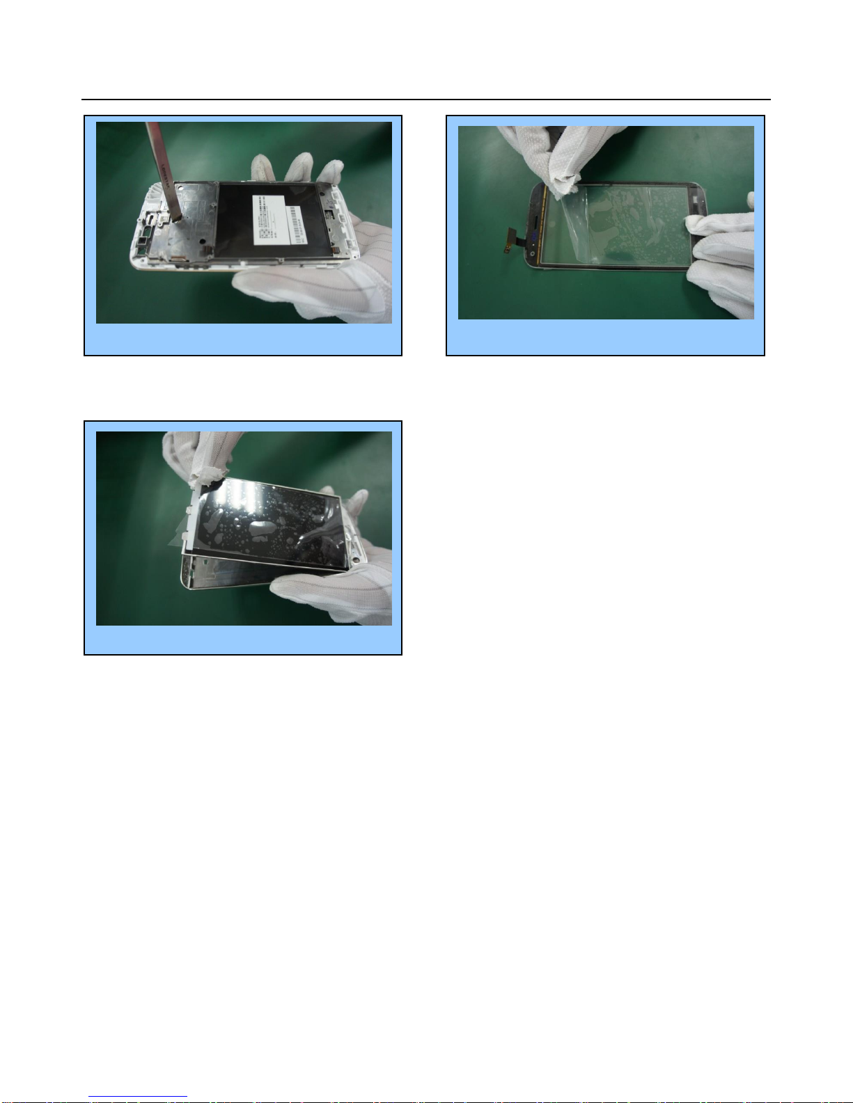
3.Assemble & Dissemble
Dissembly..................…………………………………………………………………………...6~11
Assembly………………………………………………………………………………………...12~17
6. Trouble Shooting Guide …..…………………………………………………………………….28~39
7. Upgrading ………………………………………………………………………………………. 40~42
8. CIT testing…………………………………………………………………………………………….43

Customer Service Service Manual
3/ 44
CHAPTER 1 INTRODUCTION
SPEC:
Network:
2G: M 850/900/1800/1900
3G: 900/1700/1900MHz(Option)
Size:146*73*9.7mm
Bluetooth:Support BT 4.0
Wi-Fi: 802.11b, 802.11g, 802.11n
Lithium Battery: 2000mAh Lipolymer battery
USB: Micro USB 2.0
Studio5.0II Main Function
Full Touch Smartphone
Android 4.2
CPU MT 6572W (1.3GHZ, dual-core)
5.0 " FWVGA IPS LCD
Camera:5.0MP camera AF , sub: 0.3MP FF(PIP)
BT 4.0 , WIFI :802.11b, 802.11g, 802.11n
FM ,GPS, SENSOR, PIP
Flash Memory: 4GB+512MB
Dual SIM

Customer Service Service Manual
4/ 44
CHAPTER 2 SERVICE TOOLS
Voltage regulator
Multimeter
Iron
Hot air gun
Solder wire, soldering paste
Computer and software download cable
Metal tweezers, Screw driver etc
Pick
Driver
Tweezers
Wrist
groun
ding
Antistatic
SW
upDownlo

Customer Service Service Manual
5/ 44
CHAPTER 3 DISASSEMBLY AND ASSEMBLY
3.1 DISASSEMBLY
Remove the Battery cover…….……..………………... 1
Remove the Middle cover…………….…………..…2
Remove the RF coaxial Line…………….…………………4
Remove the LCD FPC………………..………............………..5
Remove the Power key Plastic……….……………..……..3
Remove the Main camera………...………………….……... 6

Customer Service Service Manual
6/ 44
Remove the screw……………..………………………........……7
Remove the PCBA………………..……………….........……..8
Remove the speaker PCBA……….………………………10
Remove the TP by sucker…………………..…….……...…11
Remove the TP……………………………………….……….....12
Remove the induction gum cover……………..…………….9

Customer Service Service Manual
7/ 44
Finished。。。。。。。
Remove the LCD by tweezers………………………….…….13
Stick TP and LCD protection film…………….…………14
Remove the LCD……………………………………….………….15

Customer Service Service Manual
8/ 44
3.2 ASSEMBLY
Install the PCBA……………..……………….………..4
Install the TP…………………..………………....……3
Install the LCD..……………………..…..……….…..…1
Tear off protection film………………………………….2
Install the speaker PCBA…………..……….………...5
Install the RF coaxial Line……..…………………………...... 6

Customer Service Service Manual
9/ 44
Install t he power key…………...……………………………11
Install the back cover ……………………….……………...…12
Install the RF Line…….…………………………...……………10
Install the Main camera………………....…………………... 9
Install the LCD FPC...……………..…………………………..…7
Install the 1 screws..…………………………..…….……………8

Customer Service Service Manual
10 / 44
Finished………
Install the Battery cover.………………………………………14

Customer Service Service Manual
11 / 44
CHAPTER 4 SYSTEM BLOCK DIAGRAM
5.1 PCBA A-Side
J1003 Earphone connector.
bug by damaged.
Earphone no sound
J1203 I/O Connector
bug by damaged No charge in,
Cannot upgrade Software
U301 Flash Bug by damaged
Cannot power on, cannot
upgrade software.
U402 Charge IC
Bug by damaged.
Does not charge –no charge
in
U101 CPU Bug by damaged
Cannot power on. No RF
signal. No display or display
abnormality
U401 Power IC Buy by
damaged,Cannot power on.
No charge in.
Speaker no sound.
U701 BT/WIFI/FM/GPS
IC. Buy by damaged.
BT/WIFI/FM/GPS Not
work
J1205 Battery connector
Bug by damaged.
Not power on.
Not charge in
U501 RF IC
Bug by damaged.
No signal
Can’t power on.
U601/U602/U606
WCDMA PA
Bug by damage.
No signal.
U605 GSM PA
Bug by damaged.
No signal. Large current

Customer Service Service Manual
12 / 44
PCBA B-Side
J1204 /J1206 SIM
Connector
Buy by damaged. Phone
Can't Access SIM Card.
J1205 T-Flash connector
Bug by damaged.
Can't Access T-Flash Card.
J901 Camera connector
Bug by damaged.
Can’t take photos.
J903 FPC connector
Bug by damaged.
Front camera not work.
J802 TP Connector
Bug by damaged.
TP not work.
U901 LED driver IC
Bug by damaged.
LED no lights
J801 LCD Connector
Bug by damaged.
LCD No display or
display abnormality
J1001 FPC Connector
Bug by damaged.
Speaker and vibrator
not work.
U1102
Geomagnetic sensor
Bug by damaged.
Sensor failure
U1101 three-axis accele
ration sensor.
Bug by damaged.
Sensor failure

Customer Service Service Manual
13 / 44
Side A layout
Side B layout

Customer Service Service Manual
14 / 44
CHAPTER 5 UNIT CIRCUIT PRINCIPLE INTRODUCTION
MT6572 INTRODUCTION
7.1 System Overview
MT6572 is a highly integrated baseband platform incorporating both modem and application
processing subsystems to enable 3G smart phone applications, with integrated Bluetooth, WILAN
and GPS modules. The chip integrates a Dual-core ARM○
R cortex-A7 MPcoreTM operating up to
1.2Ghz,an ARM Cortx-R4 MCU and a powerful multi-Standard Video accelerator. MT6572 supports
various interfaces, including parallel/serial NAND flash memory and 32-bit LPDDR2 for optimal
performance, and supports booting from SLC NAND or eMMC to minimize the overall BOM
cost.Inaddition, an extensive set of interfaces and connectivity peripherals are included to interface
to cameras , touch-screen displays, MMC /SD cards.
Ln
MM

Customer Service Service Manual
15 / 44
5.1.1 Introduction for baseband chip CPU part circuit
Base station
interface
RF TX
Control
GPS
Control
RF RX
Control
WIFI BT
Control
Camera
Control
LCD
Control
Key
Control
SIM
Control
T-Flash
Control

Customer Service Service Manual
16 / 44
5.1.2 Baseband CPU circuit introduction for Modem

Customer Service Service Manual
17 / 44
5.2.3 System Overview
MT6323 is a power management system chip optimized for 2G/3G handsets and
smart phones, especially based on the MdeiaTek Mt6572 system solution. MT6323
contains 3 buck converters and 24 LDOs, which are optimized for specific 2G/3G/smart
phone subsystems. MT6323 provides mono 0.7W into 8Ω, high efficiency Class AB/D
audio amplifiers and flexibility for various applications of indicator LED drivers. It
supports up to 4 channel LEDs with independent controlled. Flexible control includes:
register mode, PEM mode and breath mode.

Customer Service Service Manual
18 / 44
5.2.4. PM IC MT6323
SIM CONTROL
CHARGER
VBAT INPUT
CONTROL SIGNAL
AUDIO
ALDO OUTPUT
DLDO OUTPUT

Customer Service Service Manual
19 / 44
5.1.5 System Overview
The MT6166 is a RF transceiver targeted at high speed 2G/3G-FDD/TDD multi-mode smart
phone and tablet computers implanted in 40nm CMOS. The RF transceiver function is fully
integrated. This document briefly introduces the RF macros in MT6166.

Customer Service Service Manual
20 / 44
5.1.6 RF -MT6166
5.1.7 I/O connector (5PIN)
Data Input
Data Transition
Power supply
Power
supply
Signal in
Crystal
26MHz
Other manuals for Studio 5.0 II
1
Table of contents
Other Blu Cell Phone manuals