Blue Line Thermal Wave 5M User manual

Thermal Wave®5M
Service and Operation Manual
BLUELINE Equipment Co. LLC
2604 Liberator Dr., Prescott, AZ 86301 1-928-445-3030

BLUELINE THERMALWAVE®5M I
Congratulations on your purchase of the
THERMALWAVE®5M truck mount
cleaning unit. This instruction/parts manual
is a guide for operating and servicing your
BLUELINE unit.
Proper operation and service are necessary to
ensure the outstanding performance of this unit.
When properly maintained, your truck mount will
have a long and trouble-free life.
The following service methods outlined in this
manual are detailed in a manner that operation and
servicing may be performed properly and safely.
Because service levels vary due to the skill of the
mechanic, tools and parts availability, ensure that
prior to attempting any repair, you are familiar with
this equipment and have the proper tools. Any
questions regarding the operation, service, or repair
of this unit should be directed to your nearest
BLUELINE dealer.
The headings WARNING and CAUTION are
utilized to warn you that steps must be taken to
prevent personal injury or damage to the
equipment. Please make sure that you have read
and understand these instructions entirely before
proceeding with the operation of this unit.
THIS UNIT MUST BE INSTALLED BY THE
DEALER THAT YOU PURCHASED IT FROM
IN ACCORDANCE WITH THE BLUELINE
INSTALLATION PROCEDURES.
PLEASE ENSURE THAT THE WARRANTY
CARD IS FILLED OUT BY THE DISTRIBUTOR
THAT YOU PURCHASED THIS UNIT FROM
AND RETURNED TO BLUELINE.
Record your units serial number here for future
reference or if you should need to contact the
factory in the future for any reason.
S/N:
This service and operations manual is written
specifically for BLUELINE THERMALWAVE®
5M Truck Mount Cleaning units manufactured by:
BLUELINE EQUIPMENT LLC
2265 Crosswind Drive2604 Liberator
Prescott, AZ 86301 USA
The information contained in this document is
subject to change without notice and does not
represent a commitment on the part of BLUELINE
EQUIPMENT LLC.
All rights reserved. Copyright 2002 by
BLUELINE EQUIPMENT LLC. No part of this
work may be used or reproduced in any form or
means without the express written consent and
permission of BLUELINE EQUIPMENT LLC.
Published by BLUELINE EQUIPMENT LLC.
First printing: October 2002
Printed in USA
THERMALWAVE®5M MANUAL
PART# 49-002
June 05

BLUELINE THERMALWAVE®5M II
LIMITED WARRANTY
BLUELINE warrants your machine to be free of defects in material and workmanship. This
warranty shall extend to the designated parts for the specific period of time listed from the date
of delivery to the user. If BLUELINE receives notice of any defects during the warranty period,
BLUELINE will either, at its option, repair or replace products that prove to be defective. Any
transportation, related service labor, normal maintenance and diagnostic calls are not included.
Gasoline Engine (Through manufacturer or local dealer)______ 1 year
Vacuum Pump (Through manufacturer or local dealer)________ 18 months
Water Pump_________________________________________ 1 year
Waste Pump_________________________________________ 1 year
Engine Heat Exchanger________________________________ 1 year
Wands (Excluding shut off valve and orifices)______________ 1 year
Waste and Water Tanks________________________________ 1 year
Pressure Regulator____________________________________ 1 year
Battery (pro-rated) ____________________________________1 year
All Other Components_________________________________ 1 year
This warranty shall not apply to defects caused by improper installation or operation, inadequate
maintenance by the customer, unauthorized modification or misuse, improper repair, freezing or
damage due to hard water scaling.
Electrical components, disposable filters, belts, hoses, fittings, o-rings and other service
maintenance items are not under warranty. Components supplied by BLUELINE, but provided
by other manufacturers, will only be warranted to the extent that they are warranted to
BLUELINE.
To receive warranty service, products must be returned to a BLUELINE designated service
facility. The customer shall prepay shipping charges for products returned to BLUELINE for
warranty evaluation and BLUELINE shall pay for the return of products to the customer.
BLUELINE makes no other warranty, expressed or implied, with respect to this product.
BLUELINE disclaims the implied warranties of merchantability and fitness for a particular
purpose. Any implied warranty of merchantability or fitness is limited to the specific duration of
this limited warranty.
This warranty gives the customer specific legal rights, and you may also have other rights that
may vary from state to state, or province to province.
The remedies provided herein are the customer’s sole and exclusive remedies. In no event shall
BLUELINE be liable for any direct, indirect, special, incidental, or consequential damages,
whether based on contract, tort, or any other legal theory.

BLUELINE THERMALWAVE®5M III
Table of Contents
SECTION ONE: GENERAL INFORMATION
1. SAFETY 2
Safety, Specifications, Installation, Fuel, Engine Oil, Chemical, Water Requirements
2. RECEIVING YOUR TRUCK MOUNT UNIT 7
Dealer Responsibility, Acceptance of Shipment, Equipment Listing, Optional Equipment
SECTION TWO: INSTALLATION
3. INSTALLATION 8
Lifting the Unit into the Vehicle, Positioning the Unit into the Vehicle, Fastening Down the
Unit and Waste Tank, Dimensional Diagrams, Installation of Fuel Lines, Trailer Fuel Tank
and Fuel Line Installation, Battery Connection, Fire Extinguisher, Console to Waste Tank
Connection
SECTION THREE: OPERATION
4. SYSTEMS 15
Water Pumping System, Heat Transfer System, Vacuum System, Chemical System
5. OPERATION 19
Equipment setup, Instrumentation, Starting Your Unit, Priming the Chemical Pump, Waste
Pump, Operation, Cleaning, Upholstery Cleaning, Stair Tool Cleaning, Flood Restoration,
Shut Down and Daily Maintenance, Freeze Protection.
SECTION FOUR: MAINTENANCE and SERVICE
MAINTENANCE CHART 29
6. MAINTENANCE 30
7. GENERAL SERVICE ADJUSTMENTS 34
8. TROUBLESHOOTING 39
SECTION FIVE: PARTS and ACCESSORIES
9. ILLUSTRATED PARTS LISTINGS 49
10. ACCESSORIES 84


BLUELINE THERMALWAVE®5M 1
SECTION 1:
GENERAL INFORMATION
1. SAFETY
Safety 2
Specifications 5
Installation requirements 6
Fuel requirements 6
Engine oil requirements 6
Chemical requirements 6
Water requirements 6
2. RECEIVING YOUR TRUCK MOUNT UNIT
Dealer responsibility 7
Acceptance of shipment 7
Equipment listing 7
Optional equipment 7
SECTION 1
BLUELINE THERMALWAVE®5M
2
1. SAFETY
For Your Safety!
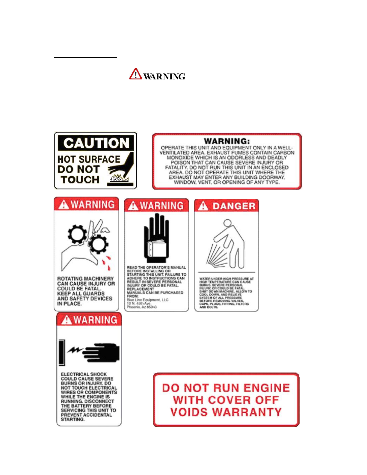
The following WARNING labels are on your THERMALWAVE®console. These labels
point out important Warnings and Cautions,which must be followed at all times. Failure to
follow warnings could result in personal injury, fatality, to yourself and/or others or property
damage. Please follow these instructions carefully! DO NOT remove these decals.

SECTION 1
BLUELINE THERMALWAVE®5M 3
!
1. Read the operator's manual before
starting this unit.
Failure to adhere to instructions could result in
severe personal injury or could be fatal.
2. Operate this unit and equipment only in a
well- ventilated area.
Exhaust fumes contain carbon monoxide,
which is an odorless and deadly poison that can
cause severe injury or death. DO NOT run this
unit in an enclosed area. DO NOT operate this
unit where the exhaust may enter a building
doorway, window, vent or other opening.
3. Gasoline is extremely flammable and its
vapors can explode if ignited.
Store gasoline only in approved containers, in
well-ventilated, unoccupied buildings and
away from sparks or flames. Never carry
gasoline or any flammable materials in the
vehicle. Fumes could accumulate inside of the
vehicle and ignite, causing an explosion.
4. This unit must be operated with the vehicle
doors open in order to ensure adequate
ventilation to the engine.
5. DO NOT operate unit if gasoline is spilled.
Do not turn ignition switch until the gasoline
has been cleaned up. Never use gasoline for
cleaning purposes.
6. DO NOT place hands, feet, hair, clothing or
any body parts near rotating or moving parts.
Rotating machinery can cause severe injury or
death.
7. NEVER operate this unit without belt and
safety guards. High speed moving parts, such
as belts and pulleys, should be avoided while
the unit is running. Severe injury, fatality or
damage may result.
8. NEVER service this unit while it is running.
High speed mechanical parts as well as high
temperature components may result in injury or
severed limbs.
9. Engine components will be extremely hot
from operation. To prevent severe burns, DO
NOT touch these areas while the unit is
running or shortly after the unit is shut off.
10. DO NOT touch the exhaust diverter valve
or any part of the exhaust system while the
system is running or for 20 minutes after the
unit is shut off. Severe burns could result.
11. Water under high pressure at high
temperature can cause burns, severe
personal injury, or fatality. Shut down unit,
allow to cool down and relieve system of all
pressure before removing caps, valves, plugs,
fittings, filters or hardware.
12. NEVER leave the vehicle engine running
while the unit is in operation.
13. Battery acid contains sulfuric acid. To
prevent acid burns, avoid contact with skin,
eyes and clothing. Batteries also produce
explosive hydrogen gases while charging. To
prevent fire or explosion, charge batteries only
in a well ventilated area. Keep sparks, open
flames, as well as other sources of ignition
away from battery at all times. Remove all
jewelry prior to servicing batteries. Keep
batteries out of the reach of children.
Before disconnecting the negative (-) ground
cable, ensure that all switches are in the off
position. If on, a spark could occur at the
ground connection terminal which could cause
an explosion if hydrogen gas or gasoline
vapors are present. ALWAYS disconnect the
negative (-) terminal first.
14. DO NOT smoke around the machine. Gas
fumes could accumulate and ignite. Battery

SECTION 1
BLUELINE THERMALWAVE®5M
4
gases are extremely flammable. This will
prevent possible explosions.
15. DO NOT damage the vehicle in any way
during the installation. When routing fuel lines
DO NOT configure the hose in any locations
where the hose or vehicle could be damaged.
Avoid contact with moving parts, areas of high
temperature, brake lines, fuel lines, catalytic
converters, exhaust pipes, mufflers or sharp
objects.
16. NEVER cut or splice any of the vehicle
fuel lines during fuel line installation. This will
result in fuel leaks and potentially dangerous
conditions. Use only the provided fuel hose for
fuel lines. When going through the vehicle
floor with fuel lines, always utilize bulkhead
adaptors. This will prevent fuel leaks and
ensure that hoses are not punctured by vehicle
vibration abrasion.
17. DO NOT exceed your vehicles weight
limit. The console with waste tank and
accessories weighs approximately 1420
pounds. Make certain that the vehicle has the
correct axle rating. This will prevent unsafe or
hazardous driving conditions.
18. High back seats are required for all vehicles
that units are to be installed for head and neck
protection. Metal partitions between the seats
and equipment are strongly recommended.
19. DO NOT operate this unit without the
water supply on and attached. The water pump
and other vital components could be seriously
damaged if the unit is operated dry. This unit is
equipped with a low pressure shut down
switch, which should NOT be bypassed.
20. Always keep your vehicle clean and
orderly. Wands, tools and accessories must be
securely stowed while driving the vehicle.
21. All high-pressure hoses must be rated at
3000 PSI and have a heat rating of 250 degrees
F. Thermoplastic hoses do not meet this criteria
and should never be used. Severe burns and
other injuries could result if hoses do not meet
these requirements.
22. Ensure that you have received proper
training from the distributor that you purchased
the unit from prior to operation.
23. This unit produces high pressure and high
temperatures. Improper use could result in
serious injury.
24. DO NOT modify this unit in any manner.
Any modification could result in serious injury
or fatality.
25. California Proposition 65 Warning: Engine
exhaust from this product contains chemicals
known by the State of California to cause
cancer, birth defects, or other reproductive
harm.
SECTION 1
BLUELINE THERMALWAVE®5M 5
SPECIFICATIONS
Engine Speed 2400 rpm (High speed dual wand)
1900 rpm (Medium speed single wand)
1500rpm(Low speed upholstery)
900 rpm (Idle)
Water Pump RPM 1550rpm
Vacuum Pump RPM 2660 rpm @ 525 cfm
Water Flow Rate 5 GPM (maximum)
Water Pump Pressure 1200 PSI (maximum)
Vacuum Relief Valve 13 in. HG
Waste Tank Capacity 115 Gallons at shutoff
Console Weight 1060 lbs.
Console Weight (with waste tank
& accessories) 1420 lbs. (2220 lbs w/full waste tank)
TORQUE VALUES
Engine Hub 720 inch/lbs. 60 ft/lbs.
Vacuum Pump Hub 192 inch/lbs. 16 ft/lbs.
JET SIZING
BLUELINE recommends that the total floor tool tip size does not exceed .06”. Using
larger jet sizes on your THERMALWAVE®unit may reduce cleaning temperatures.
Example: Four-jet wand uses four 95015 jets. (95 deg. Spray angle w/015 orifice)
.015 x 4 = .06
When using two wands while cleaning with this unit, BLUELINE recommends that the
tip size in each tool does not exceed a total of .040”.
Example: Four-jet wand uses four 9501 jets. (95 deg. Spray angle w/01 orifice)
.01 x 4 = .04 .04 x 2 tools = .08
Upholstery tool jet size: 80015 Stair tool jet size: 9502
SECTION 1
BLUELINE THERMALWAVE®5M
6
INSTALLATION REQUIREMENTS
Prior to beginning the installation, read the
ENTIRE “Installation” section of this manual.
Since the THERMALWAVE®truck mount unit
weighs (with waste tank and accessories) 1420
lbs., please adhere to the following
recommendations prior to installing the unit.
1. The unit should NOT be installed in any motor
vehicle of less than 3/4 ton capacity.
!
The console and waste tank with accessories
must NOT exceed the vehicles axle weight limit.
2. If mounting the unit in a trailer, ensure that the
trailer is rated for the total weight of the unit and
trailer. Electric or hydraulic brakes must be
provided, and strict compliance with all State and
Federal laws must be maintained.
3. If mounting in a trailer, the THERMALWAVE®
console must be positioned so that it balances
properly with respect to the trailer axle. Ten
percent (10%) of the units total overall weight (w/o
accessories or water) should be on the tongue.
4. The vehicle tires must have a load rating in
excess of the combined unit and vehicle weight.
5. BLUELINE does not recommend using any
type of flooring materials that absorb water. This
condition will result in rust and corrosion of the
vehicle floor.
6. Insulation under rubber mats should be removed
prior to installation of the unit.
FUEL REQUIREMENTS
Use unleaded fuel ONLY. NEVER use any
gasoline additives. Use only fresh, clean unleaded
gasoline intended for normal automotive use. DO
NOT use high-octane gasoline with this unit.
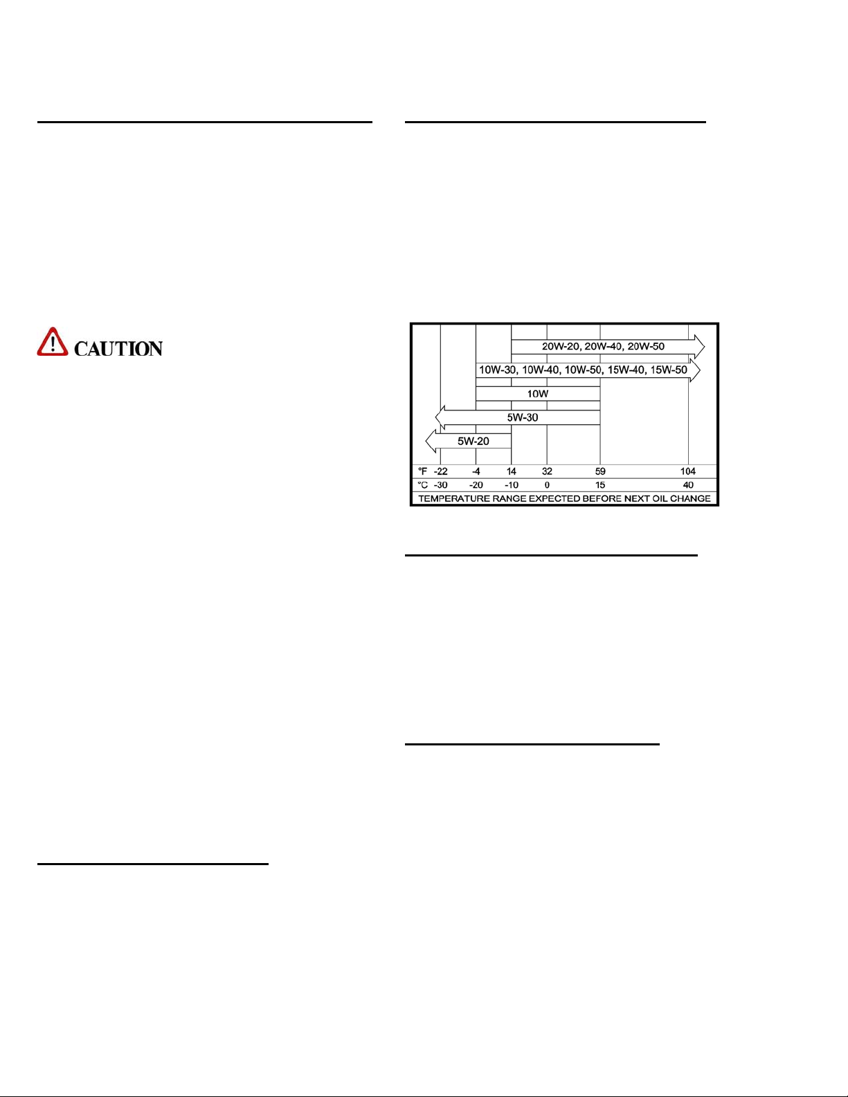
ENGINE OIL REQUIREMENTS
We recommend that you use high quality detergent
oil that meets at least API (American Petroleum
Institute) service class SF or SG. Select the proper
viscosity based on the air temperature during the
time of operation. (See table below). NOTE: the
use of less than service class SF or SG oil or
extending oil change intervals longer than
recommended can cause engine damage.
CHEMICAL REQUIREMENTS
The BLUELINE THERMALWAVE®truck
mount unit’s unique last step chemical injection
system can be used with a wide variety of water
diluted chemical compounds, either acidic or
alkaline, depending on the work to be performed.
We recommend using only the highest quality
chemistry.
WATER REQUIREMENTS
Because hard water deposits will damage the
plumbing and heat exchange systems on this unit,
BLUELINE recommends that a high quality water
softener be used in areas where the water hardness
exceeds 3-1/2 grains. If a water softener is used, it
must have a flow capacity of at least five (5) GPM
or greater, without any hose constrictions.
The use of a water softening system will reduce
maintenance and reduce down time caused by hard
water scaling. It will also enhance the performance

SECTION 1
BLUELINE THERMALWAVE®5M 7
of cleaning chemicals, which will result in greater
efficiency in lower concentrations.
2. RECEIVING YOUR
TRUCK MOUNT UNIT
DEALER RESPONSIBILITY
THE BLUELINE DEALER THAT YOU
PURCHASED THIS TRUCK MOUNT
CLEANING UNIT FROM IS RESPONSIBLE
FOR THE PROPER INSTALLATION OF THIS
MACHINE. THE DEALER IS ALSO
RESPONSIBLE FOR THE PROPER INITIAL
TRAINING OF YOUR OPERATORS AND
MAINTENANCE PERSONNEL.
ACCEPTANCE OF SHIPMENT
Your THERMALWAVE®truck mount cleaning
unit was thoroughly tested, checked and inspected
in its entirety prior to leaving our manufacturing
facility. When receiving your unit, please make
the following acceptance check:
1. The unit should not show any signs of damage.
If there is damage, notify the common carrier
immediately.
2. Carefully check your equipment and packing
list. The standard BLUELINE
THERMALWAVE®unit should arrive with the
following items as well as any optional
accessories:
EQUIPMENT LISTING
A. BLUELINE THERMALWAVE®console.
B. Operation and Service manual
C. Installation mounting plates and bolt down kit
D. Hose clamps for vacuum and fuel hoses
E. Carpet wand
F. Waste tank with shutoff switch and filters
G. Pre-Filter box and stainless steel strainer basket.
H. Waste tank filters.
I. 150 ft. of 1/4 in. high pressure solution hose
with quick connects
J. 150 ft. of 2 in. vacuum hose
K. 2 vacuum hose connectors
L. 50 ft. water supply hose with quick connect
OPTIONAL EQUIPMENT
A. Additional lengths of vacuum hose
Part # 18-003
B. Additional vacuum hose connectors
Part # 21-003
C. Additional high-pressure solution hoses
Part # 18-000
(With shutoff valve Part # 18-001)
D. Automatic waste pump kit
Part # 68-003
E. Demand pump system
Part # 68-002
F. KIT, FUEL HOOKUP CHEVY 97 & NWR. FI
Part # 69-003FI
G. KIT, FUEL HOOKUP CHEVY/DODGE FI
Part # 69-004FI
H. KIT, FUEL HOOKUP FORD FI
Part # 69-005 FI
I. KIT, FUEL HOOKUP 2003 CHEVY FI
Part #69-018FI
J. KIT, 2004 TF ADAPTER CHEVY
Part # 69-032
K. KIT, 2004 TF FUEL INJ. CHEVY
Part # 69-033
L. ADAPTOR, 2004 FORD FUEL
Part # 69-041
M. ADAPTOR, 2004 FUEL INJ. FORD
Part #69-047

BLUELINE THERMALWAVE®5M
8
SECTION 2:
INSTALLATION
3 INSTALLATION
Lifting the unit into the vehicle 9
Positioning the unit into the vehicle 9
Fastening down the unit and waste tank 9
Dimensional diagrams 10
Installation of fuel lines 12
Trailer fuel tank and fuel line installation 12
Battery Connection 12
Fire extinguisher 12
Console to waste tank connection 13
SECTION 2
BLUELINE THERMALWAVE®5M 9
3. INSTALLATION
!!!
This unit must be bolted to the floor of the
vehicle by an authorized BLUELINE
DISTRIBUTOR.
LIFTING THE UNIT INTO THE
VEHICLE
The BLUELINE THERMALWAVE®weighs
approximately 1060 lbs., a forklift is necessary to
place the unit into the vehicle. Place the forks into
the forklift slots from the front of the unit and
make CERTAIN that the forks are spread to the
maximum width of the unit.
POSITIONING THE UNIT INTO
THE VEHICLE
Vehicles vary in size and openings. Owners have
different preferences on where in the vehicle they
want their units positioned. BLUELINE strongly
recommends a side door installation for the
THERMALWAVE®. We DO NOT recommend a
rear door installation.
1.Ensure that enough space is provided to assure
adequate engine ventilation as well as room for
service and maintenance.
2. The complete unit with waste tank and
accessories MUST NOT exceed the vehicle’s axle
weight limit.
3. NEVER position the console closer than 12
inches from the bottom rear of the driver and
passenger seats.
FASTENING DOWN THE UNIT
AND WASTE TANK
!!!
Prior to drilling any holes in the vehicle floor,
ensure that while drilling, you will not damage
the fuel tank, fuel lines, or any other vital
components, which could affect the safety and
or operation of the vehicle.
A. The console and waste tank mounting holes will
serve as a template. Drill six (6) 13/32 in. diameter
holes for the console and six (6) 13/32 in. diameter
holes for the waste tank.
B. Using the provided mounting hardware kit:
1. Insert six (6) 3/8-16 x 2 ½ in. hex head cap
screws with flat washers through the
THERMALWAVE®console mounting
holes, and six (6) 3/8-16 x 2 in. hex head
cap screws with flat washers through the
waste tank mounting holes.
2. Install the provided mounting plates
underneath the vehicle floor.
3. Screw the provided 3/8-16 hex head lock
nuts on to the mounting bolts and tighten
until the console and waste tank are firmly
attached to the vehicle floor.
SECTION 2
BLUELINE THERMALWAVE®5M
10
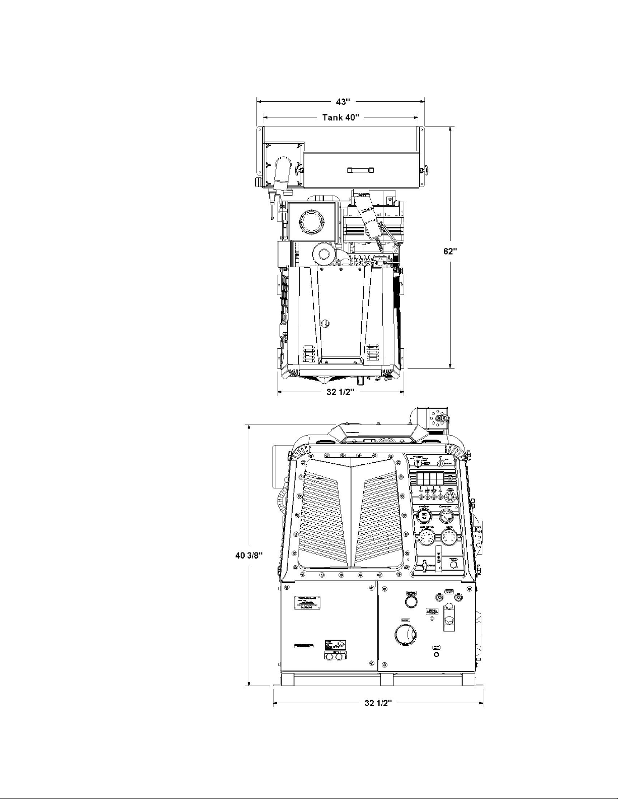
DIMENSIONAL DIAGRAM REAR MOUNT TANK

SECTION 2
BLUELINE THERMALWAVE®5M 11
DIMENSIONAL DIAGRAM BOX TRUCK TANK
DIMENSIONAL DIAGRAM SIDE MOUNT TANK
SECTION 2
BLUELINE THERMALWAVE®5M
12
INSTALLATION OF FUEL LINES
!!!
READ THESE INSTRUCTIONS IN THEIR
ENTIRETY PRIOR TO PROCEEDING.
!
The Vehicle fuel lines should NOT be spliced
under ANY circumstances. Severe injury or
fatality could result.
DO NOT damage the vehicle in any way during
the installation. When routing fuel lines DO NOT
configure the hoses in any location where the hoses
or vehicle could be damaged. Avoid contact with
moving parts, areas of high temperature, brake
lines, fuel lines, catalytic converters, exhaust pipes,
mufflers or sharp objects.
TRAILER FUEL TANK AND FUEL
LINE INSTALLATION
The following are recommendations for trailer
installations:
A. Strict compliance with all federal and state laws
must be maintained.
B. Use only fuel tanks that are manufactured
specifically for gasoline, have proper vented filling
caps, and outlet connections that are the same size
as the inlet and return connections on the unit.
C. DO NOT install fuel tanks inside any type of
enclosed trailer or vehicle.
!
NEVER carry gasoline or flammable materials in
an enclosed trailer or vehicle.
NEVER store any type of flammable material in
an enclosed trailer or vehicle.
D. Always mount fuel tanks where they will be
protected from any vehicle collision.
E. When installing fuel lines from the fuel tank to
the unit, use the proper size fuel line.
BATTERY CONNECTION
!
Explosive gases, Dangerous gases!
Batteries contain sulfuric acid. To prevent acid
burns, avoid contact with skin, eyes and
clothing. Batteries also produce explosive
hydrogen gases while charging. To prevent fire
or explosion, charge batteries only in a well
ventilated area. Keep sparks, open flames, as
well as any other sources of ignition away from
batteries at all times. Remove all jewelry prior
to servicing batteries. Keep batteries out of the
reach of children.
Before disconnecting the negative (-) ground
cable, ensure that all switches are in the OFF
position. If ON, a spark could occur at the
ground connection terminal, which could cause
an explosion if hydrogen gas or gasoline vapors
are present. ALWAYS disconnect the negative
(-) terminal first.
A. Attach the red positive (+) battery cable from
the starter solenoid on the console to the positive
(+) terminal on the battery and tighten down the
nut.
B. Attach the black negative (-) battery cable from
the ground on the console to the negative (-)
terminal on the battery and tighten down the nut.
FIRE EXTINGUISHER
BLUELINE , and many government agencies,
recommend that a fire extinguisher rated for A, B,
and C type fires be installed into any commercial
vehicle.

SECTION 2
BLUELINE THERMALWAVE®5M 13
CONSOLE TO WASTE TANK CONNECTION
*Shown with optional waste pump out kit #68-003.

BLUELINE THERMALWAVE®5M
14
SECTION 3:
OPERATION
4. SYSTEMS
Water pumping system 15
Heat transfer system 16
Vacuum system 17
Chemical pumping system 18
5. OPERATION
Preparation 19
Starting the unit 21
Priming the chemical pump 22
Automatic waste pump 22
Operation 22
Cleaning 23
Upholstery cleaning 23
Stair tool cleaning 23
Flood restoration/extraction 23
Shut down and daily maintenance 23
Freeze protection 24

SECTION 3
BLUELINE THERMALWAVE®5M 15
4. SYSTEMS
NOTE: Read and understand this section of the
manual entirely before proceeding.
This portion of the manual divides the unit up into
systems and describes how each system works.
Prior to proceeding into the operations and
maintenance sections of this manual it is
recommended that you acquire a basic
understanding of how the unit functions.
WATER PUMPING SYSTEM
See figures 3-1 and 5-10. Cold water enters the
console through the water inlet connection located
on the lower right corner of the right lower front
panel. The water then flows to the water box
through a float valve, which shuts off the water
when the water box is full.
Water then flows through a strainer in the water
box to the water pump. The water pump is
plumbed to a nitrogen charged accumulator, which
helps reduce pressure pulsations.
The water pump assembly also includes a high-
pressure and a low-pressure shutdown switch.
These switches will shut down the unit if the water
pressure exceeds 1200 PSI or drops below 50 PSI
for more than 5 seconds.
Water is then pumped to the pressure regulator
assembly, which provides and maintains the
desired pressure setting.
Water then flows from the pressure regulator
through the heli-coil heat exchanger and into the
high- pressure heat exchanger, where it is super-
heated by the engine exhaust.
The water then flows through the check valve
manifold that contains a Y-strainer and a check
valve. At this point, the chemical injection takes
place.
The hot solution mixture of water and chemicals
then flows through the solution outlet manifold to
the cleaning tool.
This unit has an automatic diverter feature.
Temperature is controlled using the thermostatic
control. When the water exceeds the temperature
setting, the electronic rotary solenoid valve
automatically positions the diverter valve, located
between the engine exhaust manifold and the hi-
pressure heat exchanger, into the muffler mode. At
this time hot water is bypassed into the water box
to preheat the water, resulting in reduced
temperature fluctuations. The temperature sensor is
located in the thermostat manifold, before the
solution outlet.
In addition, a temperature sensor is located on the
engine exhaust heat exchanger outlet. This will
shut down the engine if the water temperature
exceeds 285 deg. F. If this occurs, see the
“Troubleshooting” section of this manual to find
the cause of overheating prior to restarting your
unit.
Table of contents
Other Blue Line Cleaning Equipment manuals


