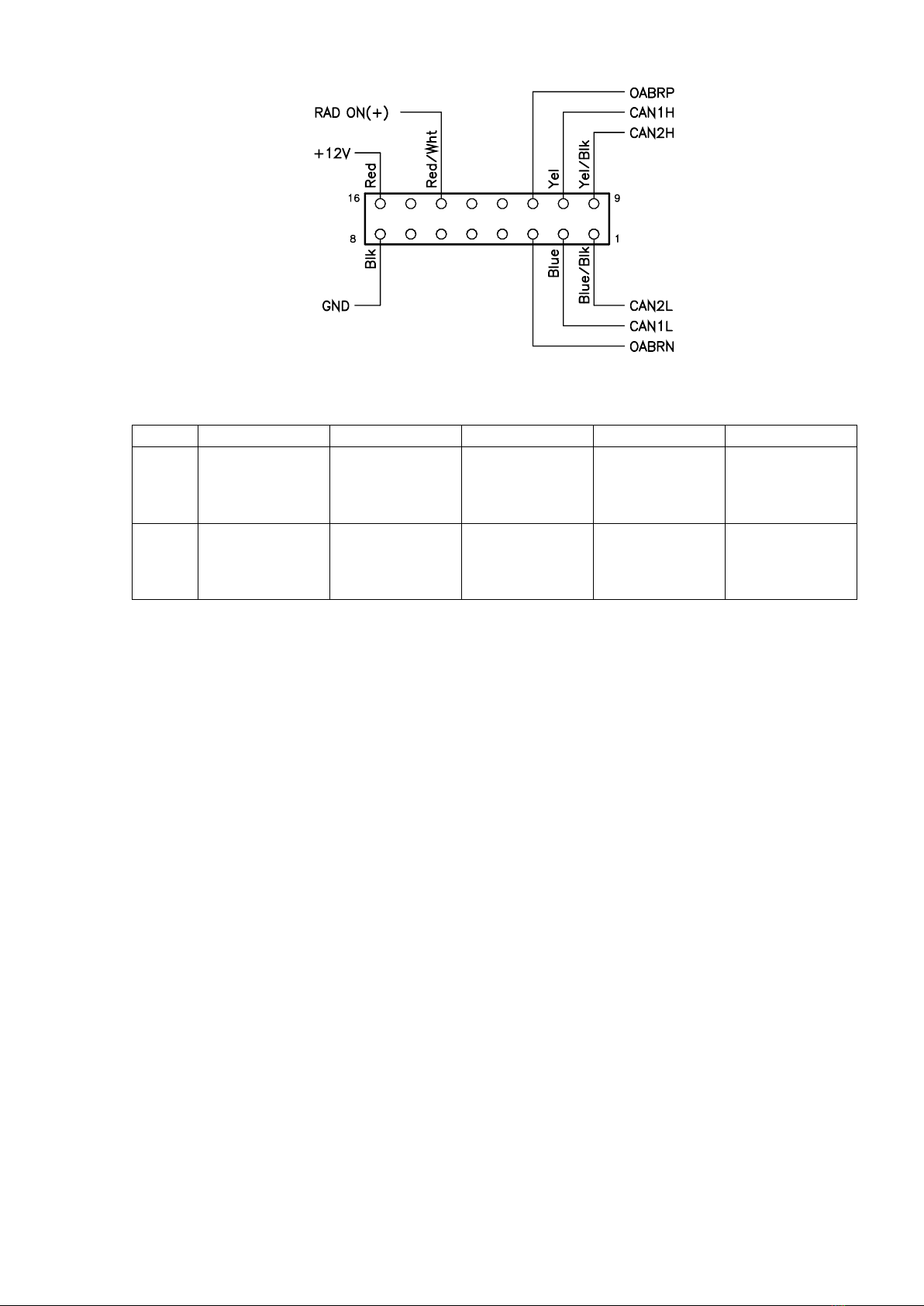
Figure 2. Connector «System» pinout
Table 1, switches features
Sport indicators
protocols
conversion
KAFAS1 protocols
conversion
Gyro sensor
protocol
conversion
Sport indicators
protocols
conversion
KAFAS1 protocols
conversion
Gyro sensor
protocol
conversion
Connections
Module should be connected to the gap of CAN bus between head unit and car, and to the OABR
interface of head unit, according to schematic shown in Fig.3, using the supplied cable (Figure 4). Cable
consists 16-pin socket for connecting to the module «System» connector, 20-pin socket for connecting to
the OABR connector of head unit (position A42*3B Figure 6.), and wires for connect to CAN bus and
power. Cable diagram shown in Figure 5. Appearance and head unit connector A42*3B pins numbering
shown in Figure 7.
Module operation
Attention: When first connect and powered, module binds to the car and can not be used with
any other. Not bounded or installed to another car module will not perform specified functions.
When ignition turn on, or connected over USB cable, module will displays their status via “CAN”
and “ETH”indicators. In the normal state indicator “CAN” indicates CAN bus activity, and should blink at
a frequency of about 10Hz. Indicator “ETH”should produce a short single flashes with a frequency of 1Hz.
If there is no indication on the “CAN” indicator, CAN wires should be verified for the correctness and
reliability connection to the CAN buses from the car and head unit. If there is no indication on the “ETH”
indicator, OABR wires should be verified for the correctness and reliability connection to the OABR bus of
head unit.
When module connected only over USB cable to the computer, it goes into Boot mode and
provides the ability to download firmware. In Boot mode both LEDs blink alternately by double flashes
series.
In the normal state module emulates ATM ECU, receives the signal from the built-in GPS receiver
and transmits it to the head unit. Additional features can be set using switches.


 LHD User manual")