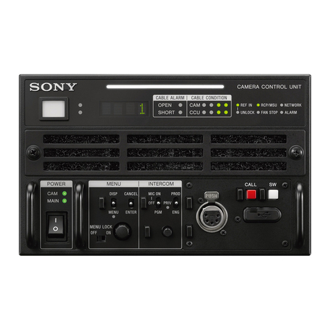
Sony HDCU3300 HD User manual

HD CAMERA CONTROL UNIT
HDCU3300
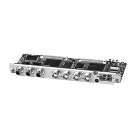
SD ENCODER UNIT
HKCU1001
MULTI INTERFACE UNIT
HKCU1003
SDI OUTPUT EXPANSION UNIT
HKCU1005
MAINTENANCE MANUAL
1st Edition (Revised 3)
Serial No. 10001 and Higher : HDCU3300 (UC)
Serial No. 30001 and Higher : HDCU3300 (J)
Serial No. 40001 and Higher : HDCU3300 (CE)
Serial No. 50001 and Higher : HDCU3300 (E3)
Serial No. 60001 and Higher : HDCU3300 (E2)

HDCU3300/MM (J,E)
!WARNING
This manual is intended for qualified service personnel only.
To reduce the risk of electric shock, fire or injury, do not perform any servicing other than that
contained in the operating instructions unless you are qualified to do so. Refer all servicing to
qualified service personnel.
!WARNUNG
Die Anleitung ist nur für qualifiziertes Fachpersonal bestimmt.
Alle Wartungsarbeiten dürfen nur von qualifiziertem Fachpersonal ausgeführt werden. Um die
Gefahr eines elektrischen Schlages, Feuergefahr und Verletzungen zu vermeiden, sind bei
Wartungsarbeiten strikt die Angaben in der Anleitung zu befolgen. Andere als die angegeben
Wartungsarbeiten dürfen nur von Personen ausgeführt werden, die eine spezielle Befähigung
dazu besitzen.
!AVERTISSEMENT
Ce manual est destiné uniquement aux personnes compétentes en charge de l’entretien. Afin
de réduire les risques de décharge électrique, d’incendie ou de blessure n’effectuer que les
réparations indiquées dans le mode d’emploi à moins d’être qualifié pour en effectuer d’autres.
Pour toute réparation faire appel à une personne compétente uniquement.
This HD camera control unit is classified as a CLASS 1
LASER PRODUCT.
CLASS 1 LASER PRODUCT
LASER KLASSE 1 PRODUKT
LUOKAN 1 LASERLAITE
KLASS 1 LASER APPARAT
CAUTION
The use of optical instruments with this product
will increase eye hazard.
CAUTION
Use of controls or adjustments or performance of
procedures other than those specified herein
may result in hazardous radiation exposure.
For safety, do not connect the connector for peripheral
device wiring that might have excessive voltage to the
following port(s).
: Ethernet connector
Follow the instructions for the above port(s).

HDCU3300/MM (J,E)
Attention-when the product is installed in Rack:
1. Prevention against overloading of branch circuit
When this product is installed in a rack and is
supplied power from an outlet on the rack, please
make sure that the rack does not overload the supply
circuit.
2. Providing protective earth
When this product is installed in a rack and is
supplied power from an outlet on the rack, please
confirm that the outlet is provided with a suitable
protective earth connection.
3. Internal air ambient temperature of the rack
When this product is installed in a rack, please make
sure that the internal air ambient temperature of the
rack is within the specified limit of this product.
4. Prevention against achieving hazardous
condition due to uneven mechanical loading
When this product is installed in a rack, please make
sure that the rack does not achieve hazardous
condition due to uneven mechanical loading.
5. Install the equipment while taking the operating
temperature of the equipment into consideration
For the operating temperature of the equipment, refer
to the specifications of the Operation Manual.
1 (P)
Voor de klanten in Nederland
Gooi de batterij niet weg maar lever deze in als klein
chemisch afval (KCA).
Für Kunden in Deutschland
Entsorgungshinweis: Bitte werfen Sie nur entladene
Batterien in die Sammelboxen beim Handel oder den
Kommunen. Entladen sind Batterien in der Regel dann,
wenn das Gerät abschaltet und signalisiert “Batterie
leer”oder nach längerer Gebrauchsdauer der Batterien
“nicht mehr einwandfrei funktioniert”. Um
sicherzugehen, kleben Sie die Batteriepole z.B. mit
einem Klebestreifen ab oder geben Sie die Batterien
einzeln in einen Plastikbeutel.
For the customers in Taiwan only

HDCU3300/MM (J,E)
2 (P)
Vorsicht!
Explosionsgefahr bei unsachgemäßem Austausch
der Batterie.
Ersatz nur durch denselben oder einen vom
Hersteller empfohlenen ähnlichen Typ. Entsorgung
gebrauchter Batterien nach Angaben des
Herstellers.
ATTENTION
Il y a danger d’explosion s’il y a remplacement
incorrect de la batterie.
Remplacer uniquement avec une batterie du même
type ou d’un type équivalent recommandépar le
constructeur.
Mettre au rebut les batteries usagées conformément
aux instructions du fabricant.
CAUTION
Danger of explosion if battery is incorrectly replaced.
Replace only with the same or equivalent type
recommended by the manufacturer.
Dispose of used batteries according to the
manufacturer’s instructions.
ADVARSEL!
Lithiumbatteri-Eksplosionsfare ved fejlagtig
håndtering.
Udskiftning måkun ske med batteri
af samme fabrikat og type.
Levér det brugte batteri tilbage til leverandøren.
ADVARSEL
Lithiumbatteri - Eksplosjonsfare.
Ved utskifting benyttes kun batteri som
anbefalt av apparatfabrikanten.
Brukt batteri returneres
apparatleverandøren.
VARNING
Explosionsfara vid felaktigt batteribyte.
Använd samma batterityp eller en likvärdig typ
som rekommenderas av apparattillverkaren.
Kassera använt batteri enligt gällande
föreskrifter.
VAROITUS
Paristo voi räjähtää jos se on virheellisesti
asennettu.
Vaihda paristo ainoastaan laitevalmistajan
suosittelemaan tyyppiin.
Hävitäkäytetty paristo valmistajan ohjeiden
mukaisesti.

1 (E)
HDCU3300/MM (J,E)
Table of Contents
Manual Structure
Purpose of this manual ........................................................... 5 (E)
Related manuals ..................................................................... 5 (E)
1. Service Overview
1-1. Service Information ................................................. 1-1 (E)
1-1-1. Tools ............................................................... 1-1 (E)
1-1-2. Cautions when Replacing
the Lithium Battery ........................................ 1-1 (E)
1-2. Notes for Replacing the Parts .................................. 1-1 (E)
1-3. Connecting/Disconnecting
the Flexible Card Wire ............................................. 1-2 (E)
1-4. Writing and Rewriting the PLD Internal Data ......... 1-3 (E)
1-5. Circuit Protection Parts ............................................ 1-5 (E)
1-6. Circuit Description ................................................... 1-6 (E)
1-6-1. HDCU3300 Common ..................................... 1-6 (E)
1-6-2. HKCU1001 ..................................................... 1-8 (E)
1-6-3. HKCU1003 ..................................................... 1-8 (E)
1-6-4. HKCU1005 ..................................................... 1-8 (E)
1-7. Notes on Repair Parts .............................................. 1-9 (E)
1-8. Unleaded Solder ....................................................... 1-9 (E)
2. Replacement of Main Parts
2-1. Replacing the Main Parts ......................................... 2-1 (E)
2-1-1. Replacing the Power Supply Unit .................. 2-1 (E)
2-1-2. Replacing the Fuse ......................................... 2-4 (E)
2-1-3. Replacing the DC Fan .................................... 2-6 (E)
2-1-4. Removing the Rear Panel ............................... 2-8 (E)
2-1-5. Replacing the OTR-1 Board ........................... 2-9 (E)
2-1-6. Replacing the SPD-15 Board ......................... 2-9 (E)
2-1-7. Replacing the Right Side Fan ....................... 2-10 (E)
2-1-8. Replacing the MB-1073 Board .................... 2-11 (E)
2-1-9. Replacing the CNB-21G Board .................... 2-12 (E)
2-1-10. Replacing the DC Fan (Rear) ....................... 2-13 (E)
3. Electrical Alignment
3-1. Preparation ............................................................... 3-1 (E)
3-1-1. Required Equipment ....................................... 3-1 (E)
3-1-2. Notes on Adjustments .................................... 3-1 (E)
3-1-3. Connection of Equipment ............................... 3-2 (E)
3-1-4. Initialization Settings ...................................... 3-3 (E)
3-2. Audio System Adjustment ....................................... 3-4 (E)
3-2-1. Microphone Level Adjustment ....................... 3-4 (E)
3-2-2. RTS Intercom Adjustment ............................. 3-5 (E)
3-3. Video and Reference Signal System Adjustment .... 3-6 (E)
3-3-1. 27 MHz VCO Free-run Adjustment ............... 3-6 (E)
3-3-2. Clock (74 MHz) Duty Adjustment ................. 3-6 (E)
3-3-3. Prompter 1/2 Level Adjustment ..................... 3-7 (E)
3-4. Video Signal System Adjustment (Front board) ..... 3-7 (E)
3-4-1. SD-SDI Input VCO Free-run Adjustment ...... 3-7 (E)
3-4-2. STAIR CASE Adjustment ............................. 3-8 (E)
3-5. SD Signal System Adjustment ................................. 3-8 (E)
3-5-1. VBS Output Level Adjustment ...................... 3-8 (E)
3-5-2. PIX Output Level Adjustment ........................ 3-9 (E)
3-5-3. WF Output Level Adjustment ........................ 3-9 (E)
4. Spare Parts
4-1. Notes on Repair Parts ..................................................... 4-1
4-2. Exploded Views .............................................................. 4-2
4-3. Electrical Parts List ......................................................... 4-8
4-4. Packing Materials & Supplied Accessories ................ 4-156
4-5. Optional Fixtures List .................................................4-156
5. Semiconductor Pin Assignments

2 (E) HDCU3300/MM (J,E)
6. Block Diagrams
Overall ............................................................................ 6-2
AT-167S .........................................................................6-3
AU-302 ........................................................................... 6-5
AVP-6 .............................................................................6-6
CPU-395 .........................................................................6-7
DPR-271A ...................................................................... 6-9
DPR-271B ..................................................................... 6-10
DRX-5 ........................................................................... 6-11
DTX-5 ........................................................................... 6-12
EN-159A ....................................................................... 6-13
EN-159B ....................................................................... 6-13
HIF-25 ........................................................................... 6-14
HIF-26 ........................................................................... 6-14
HIF-27 ........................................................................... 6-14
SDI-85 ........................................................................... 6-14
CN-2674G ..................................................................... 6-15
SDI-86G ........................................................................ 6-15
SDP-15 .......................................................................... 6-16
VDA-64A ..................................................................... 6-17
VDA-64B ...................................................................... 6-17
VIF-34G ........................................................................ 6-18
CN-3275 ....................................................................... 6-19
PS-780 ........................................................................... 6-19
PS-781 ........................................................................... 6-19
RE-276 .......................................................................... 6-19
7. Schematic Diagrams
ADO-10G ....................................................................... 7-2
AT-167S .........................................................................7-3
AU-302 ......................................................................... 7-14
AVP-6 ........................................................................... 7-16
CN-2672G ..................................................................... 7-25
CN-2673 ....................................................................... 7-26
CN-2674G ..................................................................... 7-26
CN-2700 ....................................................................... 7-27
CN-2718 ....................................................................... 7-27
CN-2805G ..................................................................... 7-27
CNB-21G ...................................................................... 7-28
CPU-395 ....................................................................... 7-30
DPR-271A .................................................................... 7-36
DPR-271B ..................................................................... 7-52
DRX-5 ........................................................................... 7-68
DTX-5 ........................................................................... 7-77
EN-159A ....................................................................... 7-85
EN-159B ....................................................................... 7-93
HIF-25 ......................................................................... 7-101
HIF-26 ......................................................................... 7-102
HIF-27 ......................................................................... 7-103
MB-1073 ..................................................................... 7-104
OTR-1 ......................................................................... 7-108
SDI-85 ......................................................................... 7-120
SDI-86G ...................................................................... 7-121
SDP-15 ........................................................................ 7-123
VDA-64A ................................................................... 7-138
VDA-64B .................................................................... 7-139
VIF-34G ...................................................................... 7-141
CN-3275 ..................................................................... 7-144
PS-780 ......................................................................... 7-145
PS-781 ......................................................................... 7-147
RE-276 ........................................................................ 7-149
Frame Wiring .............................................................. 7-152
8. Board Layouts
AT-167 ............................................................................ 8-2
ADO-10 .......................................................................... 8-4
AU-302 ........................................................................... 8-4
CN-2672 ......................................................................... 8-5
CN-2673 ......................................................................... 8-5
CN-2674 ......................................................................... 8-5
CN-2700 ......................................................................... 8-5
CN-2718 ......................................................................... 8-5
CN-2805 ......................................................................... 8-5
AVP-6 ............................................................................. 8-6
CPU-395 ......................................................................... 8-8
DPR-271A .................................................................... 8-10
DRX-5 ........................................................................... 8-12
DTX-5 ........................................................................... 8-14
EN-159 .......................................................................... 8-16
CNB-21 .........................................................................8-18
HIF-25 ........................................................................... 8-18

3 (E)
HDCU3300/MM (J,E)
HIF-26 ........................................................................... 8-19
HIF-27 ........................................................................... 8-19
OTR-1 ........................................................................... 8-20
MB-1073 ....................................................................... 8-22
SDI-85 ........................................................................... 8-23
SDI-86 ........................................................................... 8-25
SDP-15 .......................................................................... 8-26
VDA-64 ........................................................................ 8-30
VIF-34 ........................................................................... 8-31
CN-3275 ....................................................................... 8-32
PS-780 ........................................................................... 8-33
PS-781 ........................................................................... 8-35
RE-276 .......................................................................... 8-36


5 (E)
HDCU3300/MM (J,E)
Purpose of this manual
This manual is the maintenance manual of the following models :
HD Camera Control Unit HDCU3300
SD Encoder Unit HKCU1001
Multi Interface Unit HKCU1003
SDI Output Expansion Unit HKCU1005
This manual intended for use by trained system and service engineers describes
(service overview and the circuit overview, the main part replacements, electrical
alignment, parts list, semiconductor pin assignments, block diagrams, schematic
diagrams, board layouts.) required for parts-level service.
Related manuals
Beside this Installation Manual, the following manuals are available for the unit.
.Operation Manual (Supplied with HDCU3300)
This manual describes how to operate the HDCU3300.
.Installation Manual (Available on request)
This manual is intended for use by trained system and service engineers, and
describes the information regarding the installation of the unit and the information
that premises the service based on components replacement.
For obtaining, contact your local Sony Sales Office/Service Center.
Part number : 9-968-307-0X
.“Semiconductor Pin Assignments” CD-ROM (Available on request)
This “Semiconductor Pin Assignments” CD-ROM allows you to search for
semiconductors used in Broadcast and Professional equipment.
This manual contains a complete list of semiconductors and their ID Nos., and
thus should be used together with the CD-ROM.
Part number: 9-968-546-0X
Manual Structure


1-1 (E)
HDCU3300/MM (J,E)
Section 1
Service Overview
1-1. Service Information
1-1-1. Tools
Sony P/N Name
A-1153-700-A Extension board EX-982*1
A-1153-701-A Extension board EX-983*2
A-1215-624-A Extension board EX-1002*3
J-6480-010-A Alignment sleeve*4
Remover HC-001
J-7120-140-A PLD download tool*5
_Cotton swab*6
*1 : Extension board for front plug-in board
*2 : Extension board for rear plug-in board
*3 : Extension board for SDP-15 board
*4 : For female optical connector
*5 : PLD data download cable
*6 : Commercially available
For cleaning optical contact block (4 mm or less in diameter)
1-1-2. Cautions when Replacing the Lithium
Battery
The lithium battery is installed on the AT-167S board. This
lithium battery is used to back up the real-time clock
(RTC). RTC stops operating when the battery life expires.
Replace the battery and reset DATE/TIME on the C11
(C12*) DATE page in the configuration menu. (refer to
Installation Manual Section 3 “Menu Settings”.)
*: Menu “C11” changes to “C12” when the EN-159 board is installed.
AT-167S board/CR2032: Sony part number (1-528-174-
11)
c
Ensure that the battery is installed with +and _poles
connected to the correct terminals. An incorrect connection
may cause an explosion or leakage of fluid.
1-2. Notes for Replacing the Parts
The unit cannot use the following boards that are not G
type.
board name
CN-2672G
CN-2674G
CN-2805G
CNB-21G
SDI-86G
VIF-34G
Also, flexible card wires with a silver contact (terminal)
cannot be used.

1-2 (E) HDCU3300/MM (J,E)
1-3. Connecting/Disconnecting the
Flexible Card Wire
The flexible card wires are used to connect between the
following boards. Life of flexible card wire will be signifi-
cantly shortened if it is bent. Be very careful not to bend
the flexible card wire.
Three types of different-shaped connectors are used in
HDCU3300. (Type A to type C)
Because the direction of the flexible card wire is different
depending on the shape of the connector, be careful when
connecting the flexible card wire.
Disconnecting
1. Turn off the power.
2. Slide or raise the portion A in the direction of the
arrow to unlock and pull out the flexible card wire.
Connecting
m
.Do not insert the flexible card wire sideways.
.Confirm that there is no stain or dust on the contact
surface of the flexible card wire.
1. Slide or raise the portion A in the direction of the
arrow and securely insert the flexible card wire into
the deep end of the connector.
2. Return the portion A to its original position and lock
the connector.
n
When connecting the flexible card wire, check the connec-
tor shape, and great care should be taken for the direction
of the contact surface or isolation surface (blue).
(Refer to illustration of the type A to type C.)
Type A
Type B
Type C
A
Isolation surface (blue)
A
Recessed portion
Connector
A
Isolation surface (blue)
Connector
Connector
A

1-3 (E)
HDCU3300/MM (J,E)
1-4. Writing and Rewriting the PLD
Internal Data
HDCU3300 uses the PLD (Programmable Logic Device)
that supports the e-Production (EPR) system to write and
rewrite the internal data.
If the parts listed below needs to be replaced or if PLD
needs to be upgraded, contact your local Sony Sales
Office/Service Center.
n
The part number of PLD (or ROM for PLD) in which data
is not written yet, is shown in “Spare Parts”.
Therefore, if part replacement is required, write the data by
the following procedure.
In the case of the PLD type that runs on the program stored
in external ROM, the PLD has only to be replaced and data
needs not to be written only if the specific PLD is defective.
e-Production system has the advantages shown
below.
.To write/rewrite the PLD internal data:
1. The standard fixture (cable) can be used.
2. The standard software (PLD Download Tool) can be
used.
.The PLD internal data is controlled in the Sony Database
Server under the name Project file (E_xxx_xxx_xx_xx).
.The printed circuit board is equipped with the standard
connector (EPR connector) to write the PLD internal
data. The indication “EPR”is shown on the printed
circuit board.
Corresponding PLDs
Board name
PLD/ROM EPR connector Version Project file No.
SOFT
AT-167S V1.10
CPU-395 V1.05
PLD
AT-167S
IC601*1, IC603 CN601 V1.09 E_000_001_93_16
AVP-6
IC302, IC310*2CN3 V1.02 E_000_001_94_12
CPU-395
IC312*3, IC315 CN301 V1.00 E_000_002_00_02
DTX-5
IC401, IC505*4,
IC506*4CN501 V1.08 E_000_001_95_18
DPR-271A
IC211, IC401*5, CN301 V1.06 E_000_002_02_05
DPR-271B
IC211, IC401*5, CN301 V1.07 E_000_003_38_05
DRX-5
IC211, IC213*6,
IC214*6, IC215*6CN3 V1.05 E_000_001_96_19
SDP-15*10
IC203, IC312,
IC307*7CN301 V1.01 E_000_002_01_04
OTR-1
IC1, IC601*8, CN601 V1.02 E_000_003_37_01
EN-159A/159B
(HKCU1001/1003)
IC210, IC501,
IC502*9, IC504*9CN501 V1.02 E_000_001_98_12
*1 : IC601/AT-167S is a ROM for IC603/AT-167S.
*2 : IC310/AVP-6 is a ROM for IC302/AVP-6.
*3 : IC312/CPU-395 is a ROM for IC315/CPU-395.
*4 : IC505, IC506/DTX-5 is a ROM for IC401/DTX-5.
*5 :
IC302, 303, 304, 305, 306/DPR-271 is a ROM for IC211, IC401/DPR-
271.
*6 : IC213, IC214,IC215/DRX-5 is a ROM for IC211/DRX-5.
*7 :
IC307/SDP-15 is a ROM for IC203, IC312/SPD-15.
*8 :
IC601/OTR-1 is a ROM for IC1/OTR-1.
*9 :
IC502, IC504/EN-159A/159B is a ROM for IC210, IC501/EN-159A/
159B.
*10 : The data in the PLD of the SDP-15 board can also be written or
rewritten via the AVP-6 board. Turn on switch S4-8 on the AVP-6
board.
n
After having written or rewritten the data in the PLD of the
SDP-15 board via the AVP-6 board, turn off switch S4-8
on the AVP-6 board.

1-4 (E) HDCU3300/MM (J,E)
Equipment required
.PLD download tool (Sony part number : J-7120-140-A)
The cable to connect PC to HDCU3300.
.PC
A PC having parallel port.
A PC in which the PLD Download Tool software is
already installed.
For the applicable OS and the operating environment,
refer to “Download Tool Operating Instruction for
Device Programming”.
Data writing procedure
Data writing procedure in the PLD (or ROM for PLD) is
outlined below.
For details of data writing procedure, refer to “Download
Tool Operating Instruction for Device Programming”,
which is available in the same site where the PLD Down-
load Tool software is available.
Step 1 Prepare the Project file.
n
Download the Project file from the Sony Database
Server.
Step 2 Turn off the power of HDCU3300.
Connect the PC parallel port to the EPR connector
of the target board using the PLD download tool
(cable).
Step 3 Turn on the power of HDCU3300.
Start the PLD Download Tool software and read
the Project file.
Step 4 Program the PLD (or ROM for PLD) with the
PLD Download Tool software.
Step 5 Upon completion of programming, check that
error message is not displayed. Turn off the power
of HDCU3300 and back on.

1-5 (E)
HDCU3300/MM (J,E)
1-5. Circuit Protection Parts
Thermistors
HDCU3300 is provided with positive thermistors for
power circuit. If an overcurrent flows in a positive ther-
mistor or it heats up to a certain degree with the increase of
the ambient temperature, its internal resistance increases
sharply to limit the current flowing in the circuit. When a
thermistor is activated, turn off the power and check the
circuit of the unit. After the cause of the problem is
removed and the device cools down, turn on the power
again. The unit will work normally. It takes about one
minute for the device to cool down.
Borad name Ref. No. Address Sony P/N
AT-167S THP1 H1 (A side) !1-533-817-21
THP2 H1 (A side) !1-533-817-21
THP3 C1 (A side) !1-804-458-21
THP4 C2 (A side) !1-804-458-21
THP101 C3 (A side) !1-803-353-21
AVP-6 THP100 H4 (A side) !1-803-615-21
THP101 H4 (A side) !1-803-615-21
THP102 H2 (A side) !1-804-616-21
THP103 H2 (A side) !1-804-458-21
THP104 H3 (A side) !1-804-616-21
THP105 H3 (A side) !1-804-616-21
THP106 H2 (A side) !1-804-616-21
CPU-395 THP1 H2 (A side) !1-804-458-21
THP2 H3 (A side) !1-804-458-21
THP3 H1 (A side) !1-533-817-21
THP4 H1 (A side) !1-804-458-21
THP101 B2 (B side) !1-803-353-21
DTX-5 THP101 B1 (A side) !1-533-817-21
THP102 E1 (A side) !1-533-817-21
THP103 E1 (A side) !1-533-817-21
THP104 D1 (A side) !1-533-817-21
THP105 D1 (A side) !1-533-817-21
THP106 C1 (A side) !1-533-817-21
DPR-271A THP3 E1 (B side) !1-533-817-21
THP4 E1 (B side) !1-533-817-21
THP5 D5 (A side) !1-533-817-21
THP6 E5 (A side) !1-533-817-21
THP8 A2 (A side) !1-533-817-21
EN-159A/
159B
Borad name Ref. No. Address Sony P/N
DPR-271B THP3 E1 (B side) !1-533-817-21
THP4 E1 (B side) !1-533-817-21
THP5 D5 (A side) !1-533-817-21
THP6 E5 (A side) !1-533-817-21
THP8 A2 (A side) !1-533-817-21
DRX-5 THP1 G1 (A side) !1-533-817-21
THP2 G1 (A side) !1-533-817-21
THP3 H1 (A side) !1-533-817-21
THP4 H1 (A side) !1-533-817-21
THP5 D4 (A side) !1-533-817-21
THP6 D1 (A side) !1-533-817-21
THP7 B4 (A side) !1-533-817-21
VIF-34G THP1 A2 (B side) !1-804-458-21
THP2 A2 (B side) !1-804-458-21
THP3 C1 (B side) !1-803-615-21
THP4 A2 (B side) !1-803-615-21
THP5 A2 (B side) !1-803-615-21
THP6 A1 (A side) !1-804-458-21
THP101 B4 (A side) !1-533-817-21
THP102 C4 (A side) !1-533-817-21
THP103 H4 (A side) !1-533-817-21
THP104 J1 (A side) !1-533-817-21
THP105 H5 (A side) !1-533-817-21
THP106 H4 (A side) !1-803-615-11
THP107 H4 (A side) !1-803-615-11

1-6 (E) HDCU3300/MM (J,E)
1-6. Circuit Description
1-6-1. HDCU3300 Common
Front Boards
AT-167S board
The AT-167S board has the built-in microprocessor (SH2-
DSP). It controls various circuit boards inside the
HDCU3300 and the power supply. It also performs the
system setup including a camera.
The board performs command communication with a
camera, and with RCP, MSU, or CNU.
Also, it enables Ethernet connection by the Ethernet
controller with the built-in microprocessor.
It has the built-in signal generator circuit generating HD
and SD. This signal generator circuit establishes gen-lock
with external (main) reference and also gen-lock between
HD and SD. It controls phase of all video signal outputs.
It has the sync output of one channel enabling to switch
between the HD ternary value sync signal and the SD sync
signal.
AVP-6 board
The AVP-6 board processes the audio signal, tally, and
trunk line. It has the following functions.
.D/A-converts and outputs the MIC signals supplied from
the camera in digital format.
.A/D converts the intercom signals (ENG/PROD/PGM/
Front-Intercom) input to the HDCU3300.
.Inputs the intercom signals sent from the camera in
digital format and the A/D-converted audio signals of the
HDCU3300 to the digital mix IC, and performs line
selection, mixing, and volume control.
.D/A converts the signals processed at the digital mix IC,
and outputs it to external circuits.
.R/G tally signal I/F
.Trunk line (RS-232C/422A) I/F
CPU-395 board
The CPU-395 board has a microprocessor (SH2) and
controls the video process on the DPR-271 board.
It also communicates commands with the camera and the
AT-167S board.
DTX-5 board
The DTX-5 board processes the return signals and the
prompter signals.
This board can handle the HD-SDI/SD-SDI/VBS signals as
return signals, and convert them to the specified signals
and send them back to the camera.
.Phase adjustment is performed on the HD-SDI signal.
.The SD-SDI signal is up-converted to the pseudo-HD
signal and its signal phase is adjusted.
.The VBS signal is converted to the digital signal equiva-
lent to the SD-Digital-Component signal, and processed
in the same way as the SD-SDI signal.
The signal input as a prompter is A/D-converted, embed-
ded to the return signal and then sent to the camera.
DPR-271A board
The DPR-271A board performs the super motion output
processing for the main-line signals from the camera.
.Phase adjustment and re-clocking using line memory
.Addition processing for generating the normal-speed
signal as necessary
.Flicker correction function as necessary
.Camera signal (gamma, knee, detail, etc.) processing
function
.Has the built-in HD color bar generator
.Matches the MIC signal from the camera to the delay of
the video signal, and then multiplexes it to the SDI
signal.
DPR-271B board
The DPR-271B board performs the HD-SDI output
processing for the main-line signals from the camera.
.Phase adjustment and re-clocking using line memory
.Camera signal (gamma, knee, detail, etc.) processing
function
.Has the built-in HD color bar generator
.Matches the MIC signal from the camera to the delay of
the video signal, and then multiplexes it to the SDI
signal.
DRX-5 board
The DRX-5 board processes the main-line signals from the
camera.
.Phase adjustment and re-clocking using line memory
.Down-conversion function as necessary
.Has the built-in HD/SD signal color bar generator and
supports multiple formats
.Matches the MIC signal from the camera to the delay of
the video signal, and then multiplexes it to the SDI
signal.
.Analog character output

1-7 (E)
HDCU3300/MM (J,E)
AU-302 board
The AU-302 board is an interface to the front INCOM
connector, and has the intercom control switch and indica-
tors.
Rear boards
SDP-15 board
The SDP-15 board processes the main-line signals sent
from the OTR-1 board and the return signals to the OTR-1
board, and selects the VF signal. The board converts one
channel of the six-channel main-line serial signal sent from
the OTR-1 board from the serial to parallel signal.
Then, it separates the digital audio signal and the com-
mands multiplexed to the main line, and sends the digital
audio signal to the AVP-6 board and commands to the AT-
167S board.
Also, the return video signal is sent from the DTX-5 board,
the digital audio signal from the AVP-6 board, and com-
mands from the AT-167S board. The board then multiplex-
es the digital audio signal and the commands to the return
video signal. The return signal is then converted from the
parallel to serial signal, and sent to the OTR-1 board as the
serial signal.
The SDP-15 board selects one channel from the triple-
speed VF video signal sent from the DPR-271A board and
the normal-speed VF video signal sent from the DPR-271B
board, and then sends the signal to the OTR-1 board.
OTR-1 board
The OTR-1 board separates the main-line signals sent from
the camera, and multiplexes the return signals to the
camera. The board converts the main-line light serial signal
sent from the camera from light to electricity and from the
serial to parallel signal.
Then, it separates the multiplexed main-line signal into six
channels, converts each of them from parallel to serial, and
sends them to the SDP-15 board as the six-channel serial
signal.
Also, the OTR-1 board converts the serial return video
signal and the serial VF video signal sent from the SDP-15
board into the parallel signals and multiplexes them. The
multiplexed return signal is then converted from the
parallel to serial signal, and electricity to light, and sent to
the camera as the light serial signal.
VIF-34G board
I/F board that connects each connector on the rear panel
.I/F of MIC REMOTE, WFM REMOTE, and I/O PORT
of the D-Sub 15 pin connector
.SYNC output, CHARACTER output
.Retains serial numbers in EEPROM.
ADO-10 board
Relay board between the AVP-6 board and the rear panel
connector
.INCOM/MIC/PGM
.TRUNK LINE
.AES/EBU
HIF-25 board
The HIF-25 board has the co-axial connector for outputting
the HD/SD-SDI signals to external devices.
The board outputs two systems of the main-line system
HD/SD-SDI signal sent from the DRX-5 board, and
outputs two systems of the monitor-system HD/SD-SDI
signal.
SDI-85 board
The SDI-85 board inputs the return signals of HD-SDI
from external devices.
The board has four systems of the return input of the HD-
SDI signal, which are selected and then sent to the DTX-5
board.
SDI-86G board
The SDI-86G board mainly inputs the return signals of SD-
SDI from external devices and the composite analog return
signals.
The board has four systems of the return input of the SD-
SDI signal, which are selected and then sent to the DTX-5
board. Apart from that, it has four systems of the return
input of the composite analog signal from the CN-2674G
board, which are selected and then sent to the DTX-5
board. It also has two systems of the amplifier for the
prompter signal from the CN-2674G board that is ampli-
fied and then sent to the DTX-5 board.
HIF-27 board
The HIF-27 board has the coaxial connector for outputting
the HD/SD-SDI signals to external devices.
It outputs two systems of the main-line system HD/SD-
SDI signals sent from the DRX-5 board, and outputs one
system of the monitor-system HD/SD-SDI signals.

1-8 (E) HDCU3300/MM (J,E)
Rear boards
VDA-64A board
Same as the HKCU1001.
Insert this board to the rear side of the slot that has the EN-
159B board inserted in its front side.
VDA-64B board
The VDA-64B board is used to output the SD analog
signals (PIX, WFM signals), and to input or output
Frame_Reference to external devices.
Insert this board to the rear side of the slot that has the EN-
159B board inserted in its front side.
VDA-64C board
The VDA-64C board cannot be used in the HDCU3300.
1-6-4. HKCU1005
Front boards
DRX-5 board
Same as the DRX-5 board common to HDCU3300.
HIF-26 board
The HIF-26 board has the coaxial connector for outputting
the HD/SD-SDI signals to external devices.
It outputs two systems of the main-line system HD/SD-
SDI signals sent from the DRX-5 board in the optional
slot, and outputs two systems of the monitor-system HD/
SD-SDI signals.
1-6-2. HKCU1001
The HKCU1001 supports the basic functions of
VBS_OUT, PIX_OUT, and WFM_OUT.
Front board
EN-159A board
The EN-159A board receives 8:4:4 component digital
signal from the front side (DRX-5 board), and outputs the
main-line system SD analog composite signals (VBS, PIX,
and WFM signals). The board is equipped with the exter-
nal synchronous circuit of the reference SC (sub carrier) of
SD, and the composite signal whose external SC is locked
can be output.
Rear board
VDA-64A board
The VDA-64A board outputs the SD analog signals (VBS,
PIX, and WFM signals) to external devices.
1-6-3. HKCU1003
In addition to the functions of the HKCU1001, the
HKCU1003 supports functions including SUB_REF.
(The synchronizing function of the sub reference cannot
be used in the HDCU3300.)
Front board
EN-159B board
The EN-159B board receives the 8:4:4 component digital
signal from the front side (DRX-5 board), and outputs the
main-line SD analog composite (VBS, PIX, and WFM
signals).
Also, the board is equipped with the synchronous circuit of
the sub reference signal, and the output of the staircase
signal for the WFM sequential display.
(The synchronizing function of the sub reference cannot
be used in the HDCU3300.)

1-9 (E)
HDCU3300/MM (J,E)
1-7. Notes on Repair Parts
1. Safety Related Components Warning
w
Components marked !are critical to safe operation.
Therefore, specified parts should be used in the case of
replacement.
2. Standardization of Parts
Some repair parts supplied by Sony differ from those
used for the unit. These are because of parts common-
ality and improvement.
Parts list has the present standardized repair parts.
3. Stock of Parts
Parts marked with “o”at SP (Supply Code) column of
the spare parts list may not be stocked. Therefore, the
delivery date will be delayed.
4. Harness
Harnesses with no part number are not registered as
spare parts.
1-8. Unleaded Solder
Boards requiring use of unleaded solder are printed with a
lead free mark (LF) indicating the solder contains no lead.
(Caution: Some printed circuit boards may not come
printed with the lead free mark due to their particular size.)
: LEAD FREE MARK
m
.Be sure to use the unleaded solder for the printed circuit
board printed with the lead free mark.
.The unleaded solder melts at a temperature about 40 dC
higher than the ordinary solder, therefore, it is recom-
mended to use the soldering iron having a temperature
regulator.
.The ordinary soldering iron can be used but the iron tip
has to be applied to the solder joint for a slightly longer
time. The printed pattern (copper foil) may peel away if
the heated tip is applied for too long, so be careful.

Table of contents
Other Sony Control Unit manuals
Popular Control Unit manuals by other brands

Agilent Technologies
Agilent Technologies TwisTorr Medium-TMP X3512-64016 user manual

Keithley
Keithley 7752 user guide

Sophos
Sophos XGS Series Mounting instructions

Mitsubishi Electric
Mitsubishi Electric MELSEC Q Series user manual

Webasto
Webasto MultiControl installation instructions

Emerson
Emerson Fisher V270 instruction manual