5. Gain
Provides control over the level of input signal that can be applied to the internal signal buses
of the main unit. Balances the input levels of various devices so that the main unit controls can
be set to relatively uniform or optimum levels. 18-60 dB Gain range in MIC position, -2 to 40
dB in Line position.
1. Gate - Threshold (Thresh)
Controls the amount of input signal level neces-
sary to turn the module’s signal output on and
mute lower priority modules. Clockwise rotation
increases the necessary input signal level required
to produce audio output and mute lower priori-
ty modules.
6. MIC/Line In
MIC/Line level input on removeable screw terminal strip. Electronically balanced input.
3.Treble (Treb)
The Treble control provides +/- 10 dB at 10 kHz.
Clockwise rotation provides boost; counterclockwise rotation provides cut. Center position
provides no effect.
2. Gate - Duration (Dur)
Controls the amount of time the signal output
and priority muting of the module remains
applied to the main unit’s buses after the input
signal falls below the required minimum signal
level (set by the threshold control).
4. Bass
The Bass control provides +/- 10 dB at 100 Hz. Clockwise rotation provides boost; counter-
clockwise rotation provides cut. Center position provides no effect.
1
5
6
2
3
4
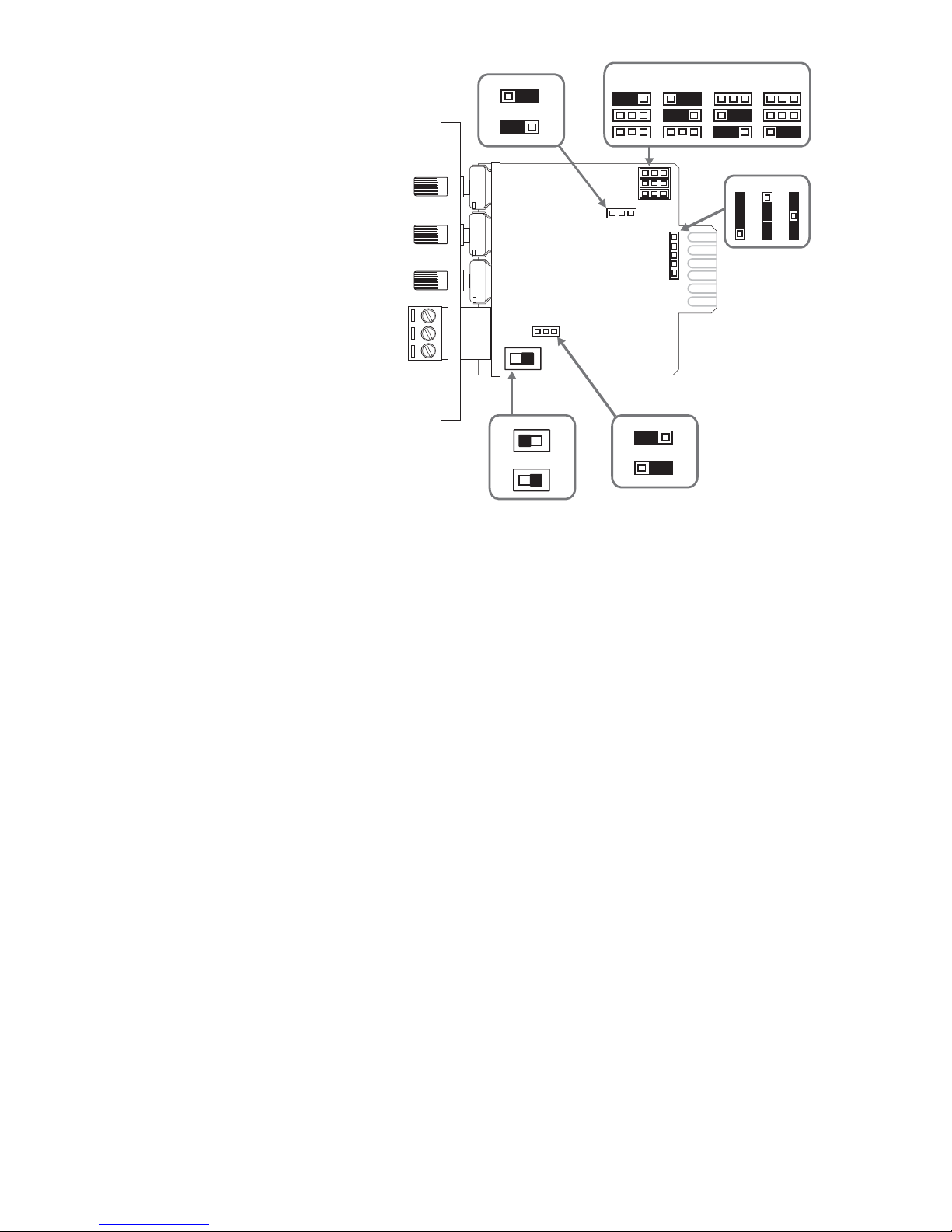
Module Installation
1.Turn off all power to the unit.
2. Make all necessary jumper selections.
3. Position module in front of any desired module bay opening, making sure that the module
is right-side up.
4. Slide module onto card guide rails. Make sure that both the top and bottom guides are
engaged.
5. Push the module in to the bay until the faceplate contacts the unit’s chassis.
6. Use the two screws included to secure the module to the unit.
WARNING:
Turn off power to unit and make all jumper
selections before installing module in unit.
Gating
Gating (turning off) of the module’s output when insufficient audio is present at the input can
be disabled. Detection of audio for the purpose of muting lower priority modules is always
active regardless of this jumper setting.
Phantom Power
24V Phantom power can be supplied to condensor microphones when jumper is set to ON
position. Leave OFF for dynamic mics.
Bus Assignment
This module can be set to operate so that the mono signal can be sent to the main unit’s
A bus, B bus, or both buses.
MIC/LINE Switch
Sets input gain range for the intended input device. MIC gain range 18 – 60 dB, LINE gain
range -2 – 40 dB.
Jumper Selections
Priority Level*
This module can respond to 4
different levels of priority.
Priority 1is the highest priority.
It mutes modules with lower pri-
orities and is never muted.
Priority 2 can be muted by
Priority 1modules and can mute
modules set for Priority Level 3
or 4. Priority 3 can be muted by
either Priority 1or 2 modules
and can mute Priority 4 mod-
ules. Priority 4 modules are
muted by all higher priority
modules. Remove all jumpers for
“no mute” setting.
*The number of priority levels avail-
able is determined by the equip-
ment the modules are used in.