manuals.online logo
Brands
  1. Home
  2. •
  3. Brands
  4. •
  5. Dorma
  6. •
  7. Door Opening System
  8. •
  9. Dorma ED900 User manual

Dorma ED900 User manual

Other Dorma Door Opening System manuals
Dorma STA Series User manual

Dorma

Dorma STA Series User manual

Dorma G-EMF Series User manual

Dorma

Dorma G-EMF Series User manual

Dorma ES 200 User manual

Dorma

Dorma ES 200 User manual

Dorma TS93 T User manual

Dorma

Dorma TS93 T User manual

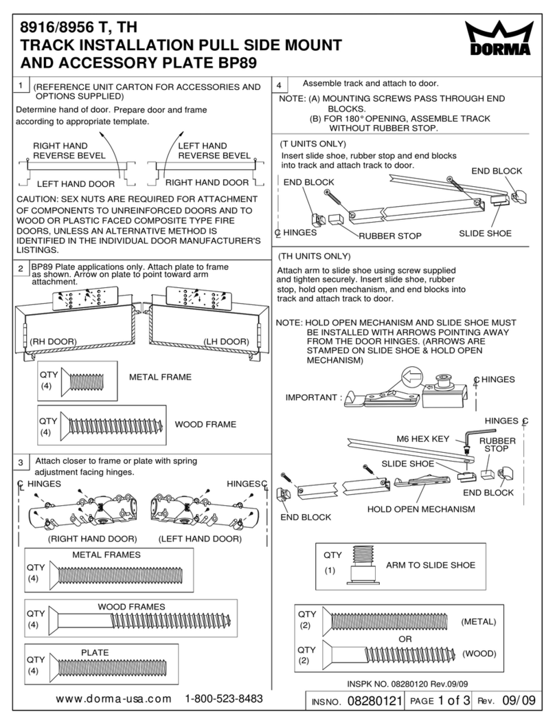
Dorma 8916 T User manual

Dorma

Dorma 8916 T User manual

Dorma RSP 80 User guide

Dorma

Dorma RSP 80 User guide

Dorma 9800FL Series User manual

Dorma

Dorma 9800FL Series User manual

Dorma PT 51 User manual

Dorma

Dorma PT 51 User manual
Dorma CS 80 MAGNEO Manual

Dorma

Dorma CS 80 MAGNEO Manual

Dorma 8956 SPA SP-6 User manual

Dorma

Dorma 8956 SPA SP-6 User manual

Dorma 8916 AF8MJ User manual

Dorma

Dorma 8916 AF8MJ User manual

Dorma CS 80 MAGNEO Guide

Dorma

Dorma CS 80 MAGNEO Guide

Dorma ED 100 User manual

Dorma

Dorma ED 100 User manual

Dorma AGILE 150 User manual

Dorma

Dorma AGILE 150 User manual

Dorma PT 40 User manual

Dorma

Dorma PT 40 User manual

Dorma 8916 PH User manual

Dorma

Dorma 8916 PH User manual

Dorma TS93 PT User manual

Dorma

Dorma TS93 PT User manual

Dorma 7436 T User manual

Dorma

Dorma 7436 T User manual

Dorma GK 20 User manual

Dorma

Dorma GK 20 User manual

Dorma 7300 PT User manual

Dorma

Dorma 7300 PT User manual

Dorma G-SR EMR Manual

Dorma

Dorma G-SR EMR Manual

Dorma 8616 PH User manual

Dorma

Dorma 8616 PH User manual

Dorma 8616 AF User manual

Dorma

Dorma 8616 AF User manual

Dorma 9600 Series User manual

Dorma

Dorma 9600 Series User manual

Popular Door Opening System manuals by other brands

Mobeye Call-Key MCK100 installation manual

Mobeye

Mobeye Call-Key MCK100 installation manual

SALICE Lapis Assembly instructions

SALICE

SALICE Lapis Assembly instructions

Cal-Royal N-F77CVR Installation instruction

Cal-Royal

Cal-Royal N-F77CVR Installation instruction

Scrigno OPEN1000 Assembly manual

Scrigno

Scrigno OPEN1000 Assembly manual

BFT WIND RMB 130B 200 installation manual

BFT

BFT WIND RMB 130B 200 installation manual

Alecto ADI-250 user manual

Alecto

Alecto ADI-250 user manual

Besam Swingmaster MP Installation, adjustment and maintenance instructions

Besam

Besam Swingmaster MP Installation, adjustment and maintenance instructions

Assa Abloy SARGENT 1431 Series instructions

Assa Abloy

Assa Abloy SARGENT 1431 Series instructions

GAL MOVFR Quick setup

GAL

GAL MOVFR Quick setup

Häfele Finetta T 70 VF manual

Häfele

Häfele Finetta T 70 VF manual

AGS D-PL Instructions for fitting, operating and maintenance

AGS

AGS D-PL Instructions for fitting, operating and maintenance

Stanley MA900ñ Installation and owner's manual

Stanley

Stanley MA900ñ Installation and owner's manual

WITTUR Hydra Plus UD300 Instruction handbook

WITTUR

WITTUR Hydra Plus UD300 Instruction handbook

Alutech TR-3019-230E-ICU Assembly and operation manual

Alutech

Alutech TR-3019-230E-ICU Assembly and operation manual

Pamex KT-INP35 Installation instruction

Pamex

Pamex KT-INP35 Installation instruction

MPC ATD ACTUATOR 50 ATD-313186 Operating and OPERATING AND INSTALLATION Manual

MPC

MPC ATD ACTUATOR 50 ATD-313186 Operating and OPERATING AND INSTALLATION Manual

Chamberlain T user guide

Chamberlain

Chamberlain T user guide

Fireco Dorgard operating guide

Fireco

Fireco Dorgard operating guide

manuals.online logo
manuals.online logoBrands
  • About & Mission
  • Contact us
  • Privacy Policy
  • Terms and Conditions

Copyright 2025 Manuals.Online. All Rights Reserved.

1
ED900 POWER CORD INSTALLATION
—
DORMA AMERICAS, Inc. Dorma Drive, Drawer AC Toll-Free: 800-523-8483 E-mail: [email protected]
08122560 08/14 Reamstown, PA 17567 Fax: 800-274-9724 Subject to change without notice
Installing the power cord
1
4
3
2
1.1 Disassemble the conduit box assembly, by removing
the pan head screw from the terminal block using a #1
phillips screw driver.
1.2 Slide the conduit box underneath the mounting plate.
1.3 Insert the pan head screw into the terminal block,
bushing and conduit box by using a #1 phillips screw
driver (5in-lbs).
Conduit box
Screw
Terminal block
1. 110V power cord
2. Conduit box
3. Cord grip
4. Wire nut
Bushing
Mounting
plate
1
The flexible power cord should not be routed through doorways, window openings, walls, ceilings, floors, or the like. The
cord should also not be attached or secured to the building structure. The cord cannot be concealed behind walls and the
like. Make sure the power cord does not become entrapped in any moving parts of the operator, door, or system.
To reduce the risk of electric shock, this equipment has a grounding type plug, that has a third (grounding) pin. This plug
will only fit into a grounding type outlet. IF the plug does not fit into the outlet, contact a qualified electrician to install
the proper outlet. Do not change the plug in any way.
For in-wall mounting: When installing the socket, please remember that the socket should be reached by hand.
(maximum 14" away)
ATTENTION! Connect the power cord to 120V 60 Hz ONLY.
WARNING! Power cords pose a rise of becoming entrapping in moving parts of the operator, door or system.
2
ED900 POWER CORD INSTALLATION
DORMA AMERICAS, Inc. Dorma Drive, Drawer AC Toll-Free: 800-523-8483 E-mail: dormaarchitectural@dorma. com
08122560 08/14 Reamstown, PA 17567 Fax: 800-274-9724 Subject to change without notice
2.1 Punch out the hole in the conduit box best suited for the
application.
2.2 Place the power cord into the grommet portion of the
cord grip and insert the cord grip into the hole using
pliers to compress it.
Hole
Conduit box
Cord
grip
Wiring the ED900
1.1 Loosen the terminal block connections and secure each
wire of the 110V power cable into its proper location on
the terminal block.
Black (live) = upper terminal
White (neutral) = lower terminal
Green (ground) = connect to ground wire
1.2 Align the mounting plate/conduit box assembly with the
bottom of the ED900 unit.
1.3 Feed the terminal block power cable through the bottom
of the plastic housing. CAUTION: DO NOT DAMAGE THE
WIRES.
2.1 Insert the male connection end of the main power cable
into the female connector inside the housing.
Terminal block Power cable
ED900 unit
Mounting plate/conduit box
Terminal
block power
cable
Housing
Male
connection
end
Female
connection
end
2
1
2