LCN ELECTRIC AUTO-EQUALIZER 4630 User manual

4630 / 4640
ELECTRIC AUTO-EQUALIZER SERIES
Princeton, IL 61356
Phone: 800 - 526 - 2400
4640
PUSH SIDE MOUNT
INSTRUCTION MANUAL FOR THE INSTALLATION AND ADJUSTMENT
OF THE 4600 SERIES ELECTRONIC LOW ENERGY DOOR OPERATOR
The 4600 Series electric Auto-Equalizer series combines all door operator and
door control functions in one package. This versatile, easy-to-install system is low
maintenance and offers the following features:
- Top jamb mounting on either side of an interior door allows 90° of power opening.
( Mounting for exterior door on the inside only.)
- Manual opening up to 170° (4630) or 100° (4640).
- Easy access to on / off and hold open switches.
- Quiet, reliable operator delivers consistent performance.
- No expensive service contracts or periodic maintenance required.
- Fail safe operator acts as a standard door closer in event of power outage.
- Low energy operator does not require guard rails or safety mats.
- Advanced, easy-to-install controller module allows independent adjustment of:
» Door Opening Speed » Delay / Trigger Time for Sequential Option
» Door Opening Force » Electric Strike Delay Time
» Hold Open Time » 90° Slow Down
» Alternate Action Timeout » Safety Scanner Lockout Time
®
TABLE OF CONTENTS
Pg. 2 ...... General Information
Pg. 3 ...... Install Mounting Plate
Pg. 4 ...... 4630 Template
Pg. 5 ...... 4640 Template
Pg. 6 ..... Installing Closer Assembly
Pg.7-8.... 4600 Series Arm Installation
Pg. 9 .... Closer Regulation & Power Adjustment
Pg. 10 ...... Controller Installation
Pg. 11 ...... Electrical Connections
Pg.12-13... Typical Wiring
Pg.14 ....... Auxiliary Electrical Device Wiring
Pg.15 ....... Controller Setting Adjustment
Pg. 16-17.. Controller Programming
Pg.18 ....... Basic Operation & Cover Installation
Pg.19 ....... Illustrated Parts List
4630
PULL SIDE MOUNT
®
9/06 ©2006 SCHLAGE LOCK Company. All rights reserved. DP# 28101R7

GENERAL INFORMATION
The 4600 series installation has three sections:
Section 1 - Fastening mounting channel to frame / electrical connections.
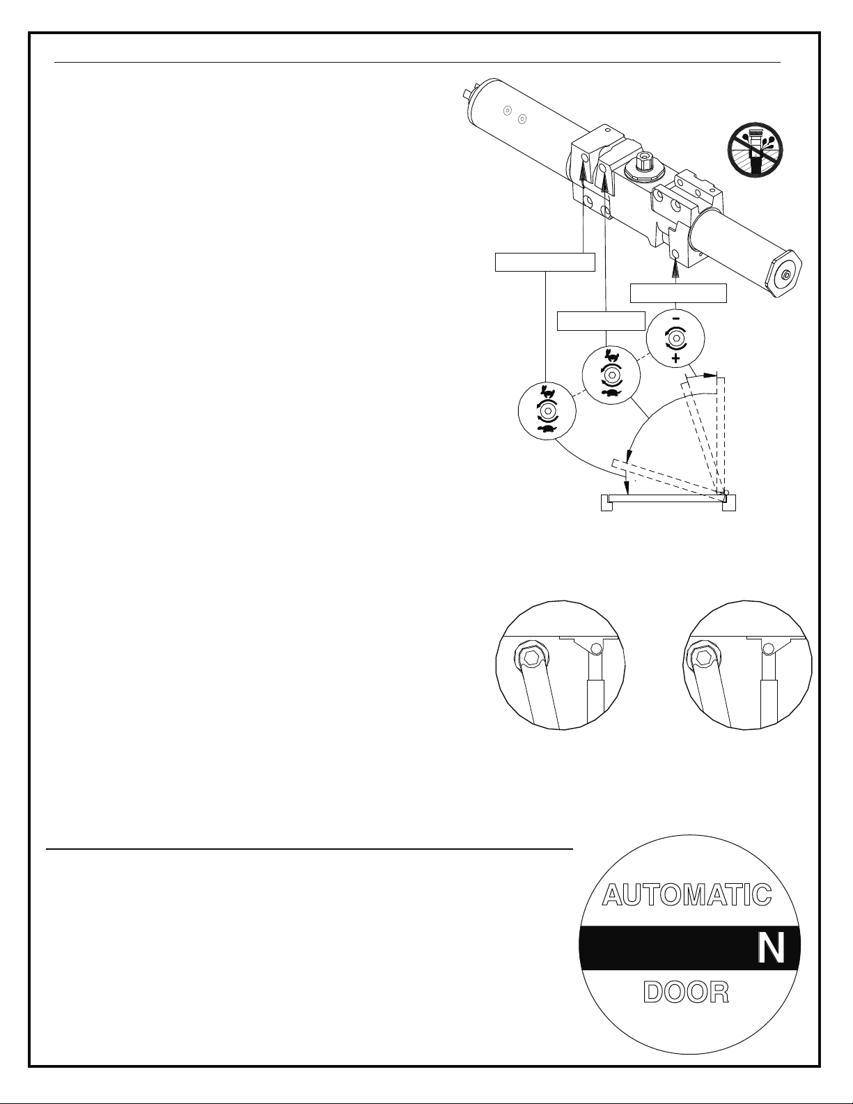
Section 2 - Installing closer body & arm assembly
Section 3 - Installation of controller and adjustment of settings.
Follow all instructions carefully. Failure to do so may result in personal injury or property damage. Use
extreme caution when dealing with high voltage. High voltage connections should be made by a qualified
professional. If you have any questions, call LCN at 800 - 526 - 2400.
The 4600 series Auto-Equalizer is designed to meet the following codes & standards:
- ANSI A156.19, section 2.1
- ANSI A117.1, section 4.13.11 requirements.
- ADA law section 4.13.12
- UL listed for use on labeled doors.
- Complies with UL & NEC requirements for Class 1 (high voltage) & Class 2 (low voltage) by
providing separate conduit connections for each.
Both the 4631 & 4642 are non-handed, non-sized door operators that provide all the standard features
of a heavy duty LCN door closer; including independent adjustment of backcheck, main speed and latch
speed functions as well as adjustable closing power: 4631 (size 1 to 4) / 4642 (size 2 to 5). Both models
are shipped with LCN's "Ultra X" all-weather hydraulic fluid for reliable operation at a wide range of
temperatures. Requirements for installation are as follows:
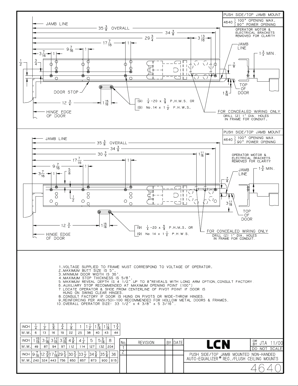
- The 4631 is designed for pull side installation on the top jamb and requires a minimum door width of
36" and a 2" min. head frame. Top rail of door must be 1 " min. and butt hinge size should not
exceed 5". Maximum pull side reveal of ".
- The 4642 is designed for push side installation on the top jamb for both standard and flush ceiling
conditions. It requires a minimum door width of 36" and a 1 " min. head frame. Top rail of door
must be at least 1 " and butt hinge size should not exceed 5". The 4642 accomodates reveals up
to 4 ". For reveal depths of 4 " - 8", requires 4642 L (Long Arm). For reveal depths greater
than 8" - consult factory.
The 4600 series can accommodate both surface and concealed wiring
applications. Maximum AC current load is 1.5 amps.
A built-in 12VDC & 24VDC power supply (rated for 1 amp combined current load) can power
peripheral actuators, electronic strikes or mag-lock devices. The 4600 series is compatible with all
LCN 7900 series actuators and scanners. High-security card readers or keypads may also be used as
actuators. The 4600 series will accept inputs from a wide variety of security systems, allowing security
personnel to regulate accessability. A 4600 will accept a fire alarm input to deactivate unit when fire
alarm is triggered. A circuit breaker and resettable fuses protect high-voltage inputs and low-voltage
output circuits, respectively. To ensure proper electrical functions, installation should be made when
temperature is between 35° F up to 120° F .
1/8
3/4
3/4
1/2 1/2
1/8
ELECTRICAL INFORMATION:
It requires 120VAC supplied to the operator.
®
This installation instruction sheet is a valuable reference and should not be discarded. It
should be given to building owner or maintenance supervisor after installation is complete.
Page 2

SECTION 1 - SECURING MOUNTING PLATE ASSEMBLY TO FRAME
Prepare door and frame per template on page 4 for 4630 / page 5 for 4640. Be sure all holes are
located correctly before drilling and/or tapping. Mounting surface of frame must be vertically level.
Conduit access holes in frame are for If using concealed wiring
option, see step 2 below. , proceed to step 3.
Refer to correct template to determine proper location for conduit. Remove appropriate conduit
plugs, exposing conduit holes in back of mounting channel, as shown in . Attach 1/2" conduit
to mounting channel, as shown in . Place mounting channel into position on frame. Once
mounting channel is in position and flush on frame, insert fasteners and tighten securely.
1.
CONCEALED WIRING ONLY !
FOR SURFACE WIRING
2.
Fig. 1
Fig. 2
NOTE: Before beginning installation, determine which conduit connection option is to be used.
CONCEALED WIRING:
SURFACE WIRING: BEFORE
Both high & low voltage conduit lines should be run to door frame and
Made accessible through two holes to be drilled in frame per proper
template on page 4 or 5.
Mounting channel must be mounted to frame running high & low
voltage conduit lines to the operator.
Fig. 1 Fig. 2
NOTICE:
Electrical power must be disconnected
The following procedures involve electrical connections and running conduit for both high & low
voltage wiring. during the installation of the 4600
series door operator. It is also important to examine the proper template for your installation to
determine the mounting channel position and correct conduit location.
HIGH VOLTAGE
LOW VOLTAGE
NOTE: The conduit set-up shown is for
a 4630 mounting. Conduit location
will vary with other mountings.
LOW VOLTAGE
CONNECTION
HIGH VOLTAGE
CONNECTION
Fig. 3
Page 3
LOW VOLTAGE
CONNECTIONS
HIGH VOLTAGE
CONNECTIONS
HIGH VOLTAGE
CONNECTIONS
LOW VOLTAGE
CONNECTIONS
END CAP
REMOVED
FROM
THIS END
END CAP
REMOVED
FROM
THIS END
3.
CONDUIT THROUGH TOP OF MOUNTING CHANNEL:
Fig. 3
Position mounting channel on frame, conncect conduit and tighten securely.
After mounting plate is attached to frame, run 1/2" conduit
to access holes in top of mounting channel. Conduit should be
connected to channel as shown here in .

Page 4
®

Page 5
TEMPLATE UPDATE
9/00
AMM
®
TEMPLATE UPDATE
JTA
11/00
LEFT HAND SHOWN, RIGHT HAND OPPOSITE

Page 6
3.
Fig. 5
Mount closer to mounting channel assembly.
Closer and clutch gear coupler's should mesh
loosely as shown in above. Line closer
mounting holes up with holes in stand-offs
attached to mounting channel. Fasten with
(4) 1/4 - 20 x 2 " machine screws provided
and tighten securely.
5/16
SECTION 2 - INSTALLING CLOSER ASSEMBLY
NOTE: Electrical components not shown.
Fig. 5
CLUTCH
TO INCREASE
SPRING POWER
TO DECREASE
SPRING POWER
INTERIOR DOOR
TABLE 1
MAXIMUM
DOOR WIDTH
NUMBER
OF TURNS
0
36"
48"
2TURNS C.W.
54"
7TURNS C.W.
Fig. 4
C.W.
EXTERIOR DOOR
TABLE 2
MAXIMUM
DOOR WIDTH
NUMBER
OF TURNS
36"
2TURNS C.W.
42"
7TURNS C.W.
1.
UNPOWERED.
At this point of the installation, the mounting channel assembly should be attached securely to door
frame. All electrical connections at the unit should be hooked up, but
2. CLOSING FORCE ADJUSTMENT:
( Fig. 4).
Tables 1 & 2.
See Turn spring adjustment
clockwise the required number of
turns to match door width as shown in
Maximum adjustments:
14 turns clockwise.
4. It is extremely important that closer is properly
aligned with motor/clutch assembly.
NOTE: Do not allow any form of lubricant to come into contact with any part of clutch assembly.

Page 7
4630 SERIES ARM ASSEMBLY INSTALLATION
5/16" LOCK WASHER
EXTENSION
ARM SET
SCREW
ROLLER
END CAP
TRACK
PLUG
ARM
SHAFT
SCREW
1. Fig. 6
2.
3.
Fig. 6
4.
5. REGULATION INFORMATION
Insert (4) track plugs into bottom of track, as shown in above. Remove track end cap, insert
track roller and replace end cap.
Mount track assembly to door, attaching securely with either (2) 1/4-20 x 1 " machine screws or
(2) No. 14 x 2 " wood screws provided.
Locate SHAFT EXTENSION, LOCK WASHER, SPACER & ARM SHAFT SCREW in fastener box.
Fit arm and spacer onto shaft extension. Place lock washer into the shaft extension so it locates
between closer shaft and shaft extension. Place wrench on top closer shaft and rotate
approx. 30°, as shown above. Fit arm assembly over closer shaft and fasten with arm shaft screw
as shown in above.
Open door partially. Pull closer arm away from frame. Fit hole in end of arm over the stud of track
roller. Tighten arm set screw, attaching arm to track.
Proceed to on page 9.
1/2
1/2
Fig. 6
NOTE: Right hand door shown,
left hand will be opposite.
SHAFT
SPACER
(2) 1/4 - 20 x 1 1/2" M.S.
OR
(2) No. 14 x 2 1/2" W.S.
ARM
ASSY
30°

Page 8
4640 SERIES ARM ASSEMBLY INSTALLATION
Fig. 7
Fig. 8
5/16" LOCK WASHER
EXTENSION
ARM
SHAFT
SCREW
ARM SET SCREW
ROD & SHOE
NOTE: Left hand door shown,
Right hand will be opposite.
Preload to 90°
as shown
1.
Fig. 7
2.
3.
4. Fig. 8
5. REGULATION INFORMATION
Locate SHAFT EXTENSION, LOCK WASHER & ARM SHAFT SCREW in fastener box.
Fit arm onto shaft extension. Place lock washer into shaft extension so it will rest between closer
shaft and shaft extension. Fit arm assembly over closer shaft so main arm is positioned at approx.
90° to operator assembly and fasten with arm shaft screw, as shown in above.
Attach rod & shoe assembly to door with (2) 1/4 - 20 x " machine screws or (2) No. 14 x 1 "
wood screws provided. The longer end of shoe should point towards hinge edge, as shown above.
Open door partially, insert rod into forearm tube, then close the door.
Insert arm set screw into rod and finger tighten. Preload arm to 90°, as shown in above.
Holding arm in this position, place a wrench on arm set screw and tighten securely.
Proceed to on page 9.
5/8 1/2
FOREARM
TUBE
MAIN
ARM

Page 9
DOOR CLOSER HYDRAULIC REGULATION & POWER ADJUSTMENT
Fig. 9
LATCH SPEED
MAIN SPEED
BACKCHECK
1. CLOSING SPEED ADJUSTMENT: Fig. 9
Fig. 9
MAIN SPEED & LATCH SPEED
MAIN LATCH SPEED
2. BACKCHECK ADJUSTMENT:
BACKCHECK
DO NOT USE AN
ABRUPT BACKCHECK SETTING.
FOR 4640 SERIES ONLY:
A.
B.
Fig. 10
C.
(See )
The hydraulic regulation of the 4600 series has
been adjusted prior to shipment. Open door to at
least 90°, and observe closing of door. Make sure
the spring power and closing speed are adequate.
If adjustments are necessary, use 3/32 allen wrench
provided and refer to door diagram shown in .
Turn screws
clockwise to slow door speed, counter-clockwise
to increase speed. The installation of the controller
will make the and regulating
screws inaccessible.
Backcheck slows the door swing as it approaches
full opening. Increase the backcheck setting only if
necessary. Adjust by turning screw
clockwise by quarter turns.
To adjust for additional
closing power at latch:
Remove forearm set screw and open door,
separating rod from forearm tube.
Remove shoe screws and flip shoe 180° as
shown in at right. Re-attach shoe to
door.
Re-assemble arm, as in steps 3 & 4 on page 8.
NOTE: Do not back regulating
screws out of closer or an oil
leak will occur
For 4640 series only
Fig. 10
STANDARD
INSTALLATION
SHOE POSITIONED
FOR INCREASED
POWER AT LATCH
LOCATING CAUTION / AUTOMATIC DOOR DECAL
1.
2.
Locate one decal on each side of door, near latch area. Decal must
be located at 58" (+/- 5") from the floor to the center line of the sign.
The decal location must be visible without interference from door trim
or auxiliary door hardware.
Clean the 6" x 6" area where decal is to be placed. Apply decal by
removing the backing and "rolling" it onto door. This will help prevent
air bubbles from being trapped under decal.
AUTOMATIC
DOOR
CAUTION

Page 10
4. Electrical power can now be safely supplied to the 4600 series operator. The controller
settings have been pre-set prior to shipment. Adjustment information is detailed on pages 15-17. It
will be necessary for the 4600 series door operator to be functional while adjustments and settings
are made. Trigger actuator device(s) and check to make sure that door opens freely. Arm assembly
motion and door travel should not make contact or have interference with any object.
SECTION 3 - INSTALLATION & ADJUSTMENT OF CONTROLLER BOARD
Fig. 11
Fig. 12
Fig. 13
NOTE: Be sure electrical power source is disconnected.
CONNECTION #1
CONTROLLER
RIBBON CABLE CONNECTION #2
120VAC POWER
CONNECTION #3
MOTOR / CLUTCH
1. MOUNT CONTROLLER TO OPERATOR
ASSEMBLY:
Fig. 11
Locate controller assembly in
shipping carton. Position the controller as
shown in . Slide onto mounting plate
assembly, guiding cut-outs in controller onto
mounting pins as shown.
2.
Fig. 12
Once the front of controller is fitted onto pins,
push entire controller into position, as shown
in . With controller in proper position,
insert (1) #8 - 32 x " flat head
screw into bottom of mounting plate, as shown.
unpainted 3/8
NOTE: For adjustments to door closer regulating screws,
controller must be removed. Do this by: Removing
power to operator, unplugging the electrical connections,
removing screw, tilting controller away from operator
and disengaging controller from mounting pins.
Follow steps 1 & 2 above to reattach.
WIRING CONNECTIONS:
1.
CONNECTION #1 Fig. 13.
There will be 3 keyed wiring harness connectors
shipped in the hardware box. The first is a ribbon
cable connector. It should be fitted into receptacles
on rear board assembly and the controller as shown
in of
2. The second connector is a 2 wire lead for the
120 VAC power and should be fitted firmly into
into receptacles on rear board assembly and the
controller as shown in CONNECTION #2 of Fig. 13.
3.
CONNECTION #3 Fig. 13
The third connector is for the motor / clutch.
The connector should be fitted firmly into
receptacle on the controller as shown
in of

Page 11
ELECTRICAL CONNECTIONS - Use copper wire only.
HAZARDOUS VOLTAGE
CAN SHOCK AND CAUSE
SEVERE INJURY.
Disconnect power before
making any electrical
connections or performing
any maintenance.
FUNCTION TERMINAL
Actuator - Normal Input (N.O.) 16 & 17 or 18 & 19
Actuator - Sequential Input (N.O.) 8 & 19
Actuator - Alternate Action (N.O.) 15 & 17
Actuator - Continuous (N.O.) 6 & 17
Sequential Output 9
Stop Side Safety (N.O.) 19 & 20
Swing Side Safety (N.O.) 19 & 21
Fire Alarm Contact (N.C.) 13 & 14 (Fire Shunt)
Auxiliary Relay Contacts(5 amp max) 10 - Common
11 - N.O.
12 - N.C.
E.S. Relay Contacts(5 amp max) 22 - Common
23 - N.O.
24 - N.C.
12V DC & 24V DC Negative* 2, 4, 13, 17, & 19
12V DC Positive* 5 & 7
24V DC Positive* 1 & 3
* Note: 1 Amp max load between 12V and 24V DC outputs
HIGH VOLTAGE ELECTRICAL CONNECTIONS
LOW VOLTAGE (CLASS 2 NEC) ELECTRICAL CONNECTIONS
SINGLE DOOR
WIRING CONNECTIONS
ANY NORMALLY OPEN
DRY CONTACT ACTUATOR
HOLD OPEN
SWITCH
CIRCUIT BREAKER
POWER SWITCH
(TO RESET-
TURN OFF THEN ON)
GROUND WIRE
(GREEN)
FIRE ALARM SHUNT
TO CONNECT TO FIRE ALARM,
CLIP LEADS ON SHUNT TO
REMOVE AND CONNECT
FIRE ALARM CONTACTS
TO TERMINALS 13 & 14
HOLD OPEN
SWITCH
CONNECTOR
FIELD CONNECTION
TERMINALS
PLUG IN CONNECTORS
FOR LCN 7920-954
ACTIVATION AND
7920-904/912
SAFETY SCANNERS
CONTROLLER
RIBBON CABLE
CONNECTOR
120 VAC
POWER INPUT
CONNECTOR
POWER TO
CONTROLLER
CONNECTOR
CIRCUIT
BREAKER
CONNECTION
1 2 3 4 5 6 7 8 9 10 11 12
13 14 15 16 17 18 19 20 21 22 23 24
ACTIVE
STOP
ACTIVE
SWING
HIGH VOLTAGE BOARD
LOW VOLTAGE BOARD
L
N

Page 12
SIMULTANEOUS PAIR WIRING CONNECTIONS
SEQUENTIAL WIRING CONNECTIONS - SIMULTANEOUS VESTIBULE
SEQUENTIAL WIRING CONNECTIONS - INDEPENDENT VESTIBULE
SEQUENTIAL
ACTUATOR
SEQUENTIAL
ACTUATOR
VESTIBULE
ACTUATOR
VESTIBULE
ACTUATOR
ANY NORMALLY OPEN
DRY CONTACT ACTUATOR
ANY NORMALLY OPEN
DRY CONTACT ACTUATOR
SEQUENTIAL
ACTUATOR
SEQUENTIAL
ACTUATOR
VESTIBULE
ACTUATOR
ANY NORMALLY OPEN
DRY CONTACT ACTUATOR

Page 13
SEQUENTIAL PAIR WIRING CONNECTIONS - SIMULTANEOUS VESTIBULE
SEQUENTIAL PAIR WIRING CONNECTIONS - INDEPENDENT VESTIBULE PAIRS
VESTIBULE
ACTUATOR
SEQUENTIAL
ACTUATOR
SEQUENTIAL
ACTUATOR
VESTIBULE
ACTUATOR
SEQUENTIAL
ACTUATOR
VESTIBULE
ACTUATOR
SEQUENTIAL
ACTUATOR

Page 14
WIRING INFORMATION FOR
ELECTRIC STRIKE / MAG-LOCK SYSTEM
FAIL
SECURE
STRIKE
FAIL SAFE
STRIKE OR
MAG-LOCK
24V DC
+
+
-
-
24V DC
WIRING INFORMATION FOR ELECTRONIC LATCHING DEVICES
12V or 24V power supply by others
FAIL SECURE
LATCHING
DEVICE
12V / 24V
POWER SUPPLY
BY OTHERS
-
+
-
+
FOR ADDITIONAL WIRING INFORMATION CONTACT LCN CLOSERS
ELECTRICAL APPLICATIONS DEPT. AT 800 - 526 - 2400
+
CONTROL
INPUT
CONTROL
INPUT
FAIL SAFE
LATCHING
DEVICE
-
+
-
12V / 24V
POWER SUPPLY
BY OTHERS
FAIL
SECURE
STRIKE
FAIL SAFE
STRIKE OR
MAG-LOCK
12V DC
+
+
-
-
12V DC
* Capacitor and diode are taped to the inside of the operator cover.
*
**
* *
*
*
*

CONTROLLER SETTING ADJUSTMENTS
Page 15
3
89
Consult diagram above. Each setting / indicators labeled #1 - #10, which correspond with numbers below.
Adjustments for #3 & #4 are made with a small flat blade screwdriver. Turn clockwise to increase speed / force or
counterclockwise to decrease speed / force. Controller functions are preset before shipment.
Factory pre-set positions are shown on controller label.
Allows operator to be turned on & off without disconnecting power. NOTE: Internal circuit
breaker is reset by turning unit off then back on.
Provides option to keep door in hold open position (fire alarm signal will override).
Adjusts opening speed of door. Most installations will be within ANSI 156.19 specifications
at maximum adjustment (see on pg. 18). Large, heavy doors and / or strong door closer backcheck
settings may require a slower speed adjustment for proper operation. As a general rule, a slower door speed
and use of an auxiliary door stop will provide smoother operation. Max. opening speed to 90° is 5 seconds.
Adjusts amount of force the door exerts when opening (15 lbs. max). Normal adjustment is
for door to open 90° or encounter an auxiliary door stop, where motor will stop. If clutch slips more than 1/4
turn when door stops, adjust OPENING FORCE down until there is minimal or no clutch slippage. If
OPENING FORCE is increased too much, it may overpower clutch & motor. Motor will stop running after 15
seconds. It will then go into HOLD OPEN DELAY and cycle through the closing sequence.
Displays a numeric value relating to the timing adjustment indicated on the mode display.
Increases time display number or change from (OFF to ON) when in programming mode.
Decreases time display number or change from (ON to OFF) when in programming mode.
Advances through programming setups indicated on Mode Indicator.
Displays operating information about internal functions and external hardware.
When programming, indicates the program mode currently being displayed.
Adjustments should
be made only if necessary.
1. ON / OFF SWITCH-
2. HOLD OPEN SWITCH -
3. OPENING SPEED -
TABLE 3
4. OPENING FORCE -
5. TIME DISPLAY -
16 = Approximately 5 Seconds.
6. UP BUTTON -
7. DOWN BUTTON -
8. MODE BUTTON -
9. OPERATING INDICATORS -
10. MODE INDICATION -
45
67
1
2
10
0FF
0N
Power Hold
Open

1. HOLD OPEN TIME:
2. 90° SLOW DOWN TIME:
3. ONE SHOT INPUT (OFF/ON):
4. EXTERIOR MODE (OFF/ON):
5. E.S. DELAY:
6. E.S. 3 SECOND POWER (OFF/ON):
7. SEQUENTIAL DELAY:
8. ALTERNATE ACTION TIME:
9. LOCKOUT TIME:
- Adjusts the amount of time door stays open after reaching the 90° position.
- The time from start of door movement to a transition at approximately 70°,
when door opening speed is reduced.
- If off, hold open delay starts upon last activation input signal. If on,
hold open delay starts upon first activation input signal and ignores all others.
- If off, door stops and hold open timer starts after door encounters first
restriction. If on, door will pause for 1 second upon first restriction(wind), then try to open again. Hold
open timer starts after door encounters second restriction.
- Controls the time between activation signal and actual door movement. Allows time for
electric latchinghardware to release before door starts to open. Default tome should only be adjusted
when using electric latching hardware.
- If off, E.S. Relay is powered entire time door is open. Releases
when door starts to close. If on, E.S Relay is powered for only 3 seconds after door is activated,
then releases.
- Controls the time from first door activation to second door activation
during sequential door application. Should only be adjusted for sequential door application
- Controls the time the door will remain open after an alternate action
input is received. Provides an automatic second input to close the door if a second alternate action
input is not received within the preset time. Should only be set if using alternate action door
application.
- Controls the time that a safety scanner input is ignored during door closing.
Should only be set if safety scanners are used.
CONTROLLER PROGRAMMING MODES
Page 16
UP
DOWN
MODE
HOLD OPEN TIME
90° SLOW DOWN TIME
ONE SHOT INPUT
EXTERIOR MODE
E.S. DELAY
E.S. 3 SEC. POWER
SEQUENTIAL DELAY
ALTERNATE ACTION TIME
LOCKOUT TIME
POWER
FIRE ALARM
NORMAL / SEQ
H.O. / ALT. ACTION
LOCKOUT TIMER
SAFETY CLEAR
SAFETY ACTIVE
1
2
3
4
5
6
7
8
9
MODE
OPERATING
INDICATORS

CONTROLLER PROGRAMMING
Page 17
Apply power to operator after all components are installed. Controller will perform a self diagnostics and Display
will show an Error Code if error is present. If no error is present, operator will be in RUN Mode ("POWER"
Operating Indicator Light "ON") and the Display will be blank.
Normal Operating Mode = Power and Safety Clear indicators on controller lit.
ERROR CODES:
E01 = Non-functional Microprocessor
E02 = No 12V and 24V power supplies
E03 = Motor / Clutch not plugged in or open coil. Resistance values (Clutch 1200 ohms) (Motor 40 to 70 ohms)
E04 = Continuous activation signal upon power up or when leaving programming mode.
If (H.O./ALT. Action) indicator on controller is lit, check hold open switch on end cap. Must be off.
If (NORMAL/SEQ.) indicator on controller is lit, check for mis wired or stuck actuator switch.
Must be N.O. contacts.
To enter programming mode, press button.
indicator will be lit and display will show programmed time. To change time, press UP or
DOWN button respectively. Adjustment 0 to 999. Default 16. To continue programming mode, press mode button.
indicator will be lit and display will show programmed time. To change time, press UP or
Down button respectively. Adjustment 0 to 26. Default 9. To continue programming mode, press mode button.
ONE SHOT INPUT indicator will be lit and display will show programmed state. To change state, press UP or
DOWN button respectively. Adjustment ON/OFF. Default OFF. To continue programming mode, press mode
button.
EXTERIOR MODE indicator will be lit and display will show programmed state. To change state, press UP or
DOWN button respectively. Adjustment ON/OFF. Default ON. To continue programming mode, press mode button.
E.S. DELAY indicator will be lit and display will show programmed time. To change time, press UP or DOWN
button respectively. Adjustment 0 to 16. Default 0. To continue programming mode, press mode button.
E.S. 3 SECOND POWER indicator will be lit and display will show programmed state. To change state, press
UP or DOWN button respectively. Adjustment ON/OFF. Default ON. To continue programming mode, press
mode button.
SEQUENTIAL DELAY indicator will be lit and display will show programmed time. To change time, press UP or
DOWN button respectively. Adjustment 0 to 100. Default 0. To continue programming mode, press mode button.
ALTERNATE ACTION TIME indicator will be lit and display will show programmed time. To change time, press
UP or DOWN button respectively. Adjustment 0 to 3. Default 0 = No Time Out, 1 = 10 Minute Time Out,
2 = 20 Minute Time Out, 3 = 30 Minute Time Out. To continue programming mode, press mode button.
LOCKOUT TIME indicator will be lit and display will show programmed time. To change time, press UP or DOWN
button respectively. Adjustment 0 to 66. Default 20. To exit programming mode, press mode button to return to
RUN mode (display blank). Programming is now complete. Activate operator to check that all function and timings
are correct. Setting can be changed at any time by pressing Mode Button to scroll to the desired Program Mode.
MODE
HOLD OPEN TIME
90° SLOW DOWN TIME
Note: Controller will automatically exit Programming Mode and return to run Mode after 15 seconds with
no input from MODE, UP or DOWN buttons.
TO RESET BACK TO FACTORY DEFAULTS: HOLD DOWN THE MODE BUTTON WHILE TURNING POWER
TO OPERATOR "OFF" THEN BACK "ON" USING THE ON/OFF SWITCH ON OPERATOR END CAP.

COVER INSTALLATION
1.
2.
Fig. 14
Depending on conduit option used and hand of door, remove proper
knock - outs from operator cover. NOTE: If concealed conduit
option is being used, do not remove conduit knock - outs.
Align cover with operator and guide into position as shown
here in . Attach cover to the operator using
(2) painted # 8 - 32 x " flat head machine screws,
as shown.
3/8
Fig. 14
TABLE 3
MAXIMUM
DOOR
WEIGHT
IN POUNDS
FASTEST OPENING TIME 0° to 80°
DOOR WIDTH IN INCHES
36" 42" 48"
100 lbs.
125 lbs.
150 lbs.
200 lbs.
3.0 sec
3.5 sec
3.5 sec
4.0 sec
3.5 sec
4.0 sec
4.0 sec
4.5 sec
4.0 sec
4.5 sec
4.5 sec
5.5 sec
TABLE 4
TYPE OF DOOR
WEIGHT PER
SQ. FT.
- Solid Core Wood
- 20 Ga.Flush Hollow Metal
- Aluminum x 1/4" Glass
- Mineral Core Door
- 16 Ga.Flush Hollow Metal
- Aluminum x 1" Glass
5.5 lbs
7.0 lbs
TABLE 3
TABLE 4
(below) lists the maximum door opening speeds specified by ANSI 156.19 for Low - Energy
Door Operators. 4630/4640 max. opening speed to 90° is 5 seconds. If weight of door is unknown, use
to determine approximate door weight.
BASIC OPERATION INFORMATION
Page 18
If fire alarm contacts are activated at time during the opening cycle or while in hold open, the 4600
series Door Operator will override function and close the door immediately. All power door functions are
stopped until the fire alarm contacts are deactivated
When triggered by actuator switch:
-Controller checks for optional swing-side safety sensor input. If activated, opening cycle is aborted.
-If sequential actuator inputs are used then the - B SEQUENTIAL DELAY timer is started.
-Auxiliary and E.S. relay contacts are triggered
-Opening cycle starts after ELECTRIC STRIKE DELAY times out.
-Motor & clutch are activated.-If sequential actuator inputs are used then the A - SEQUENTIAL DELAY output
will signal.
-Controller monitors the motor during opening cycle for door obstructions that exceed the preset OPENING
FORCE setting. If an obstruction is encountered controller will pause opening cycle forone second, then attempt to
open door again (SECOND CHANCE feature).
-Opening cycle resumes until power opening range is reached or a second obstruction is sensed.
-Opening door encounters BACKCHECK range of door closer. A strong BACKCHECK setting will cause controller
to act as though it hit an obstruction, triggering the SECOND CHANCE feature.
Some experimentation with OPENING FORCE, OPENING SPEED & BACKCHECK settings may be necessary for
applications where wind and / or air pressure problems occur.
-Controller goes into HOLD OPEN DELAY mode for preset amount of time.
-The controller will maintain the hold open mode as long as an actuator input signal is present.
The HOLD OPEN DELAY mode timer is reset with each additional actuator input signal. With each additional
sequential actuator input a sequential output signal is sent.
-Controller checks for optional push-side safety sensor input. If activated, the operator will hold door open until
sensor de-activates.
-Controller releases door for closing cycle. Closing cycle is controlled by door closer assembly.
NOTE:
1.
A
2.
3. B
4.
5.
any
any
TYPICAL 3'0"x7'0"
DOOR WEIGHT
115 lbs
147 lbs

- 3179-1
ON \ OFF
SWITCH ASSY.
4630/4640 REPLACEMENT PARTS LIST INFORMATION
Page 19
4630 - 30
ARM SET
SCREW
4630 - 3034
ROLLER
4630 - 73
END CAP
4630 - 141
TRACK
PLUG
4630 - 159
ARM
SHAFT
SCREW
4640 - 83
ARM SET SCREW
4640 - 79
ROD & SHOE
4640 - 3077
MAIN ARM
4642 ARM PARTS
4630 - 3077T
ARM ASSY.
4631 ARM PARTS
- 480
SHAFT
EXTENDER
PACKAGE
- 3454
MOTOR / CLUTCH
ASSY.
- 20 CONDUIT
COVER
-155G
DOOR
DECAL
When ordering replacement parts remember to specify Model (4640 or 4630)
in front on the desired part #. Also specify Color / Finish when required.
4630 - 3038
TRACK
ASSY.
- 3498-1
RIBBON CABLE
CONNECTOR
4630 - 61
SHAFT
SPACER
AUTOMATIC
DOOR
CAUTION
- 31 -1
END CAP
SCREW
- 3971
CYLINDER
ASSEMBLY
- 31 COVER
SCREW
- 334 - 2
BLANK
END CAP
- 3462
CONTROLLER
ASSEMBLY
- 3180
PCB
BOARD
ASSEMBLY
- 3179-2
HOLD - OPEN
SWITCH ASSY.
- 334
SWITCH
END CAP
- 3498-2
AC POWER
CABLE
- 31 MTG.
SCREW
- 72 COVER
4640 - 159
ARM
SHAFT
SCREW
This manual suits for next models
1
Other LCN Door Opening System manuals

LCN
LCN Sentronic 2310-ME User manual

LCN
LCN 4600 Series User manual

LCN
LCN 4410ME Series User manual

LCN
LCN COMPACT 6400 Series User manual

LCN
LCN 2010 SERIES User manual

LCN
LCN 4412 HSA Operation and maintenance manual

LCN
LCN 4040XP User manual

LCN
LCN 4310ME Series User manual

LCN
LCN Benchmark III 9130 User manual

LCN
LCN 1450 Series User manual