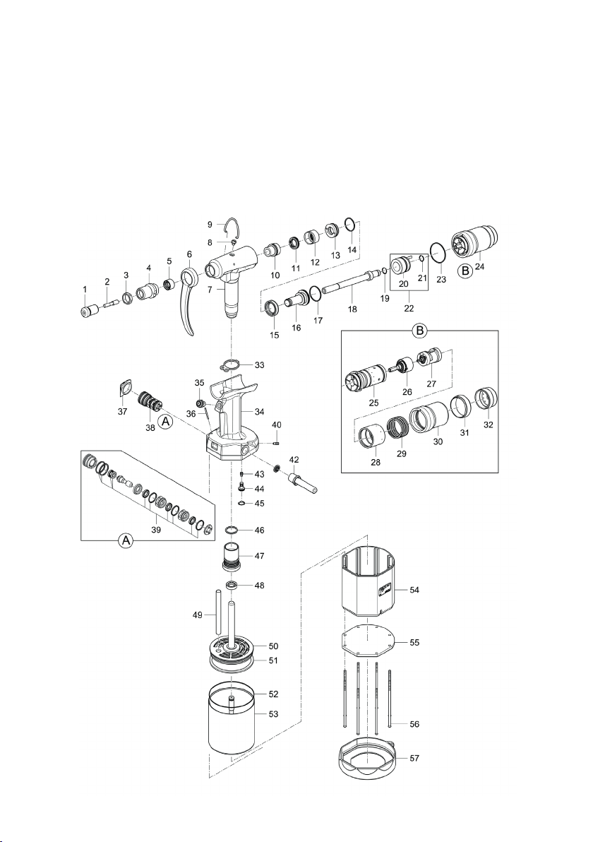
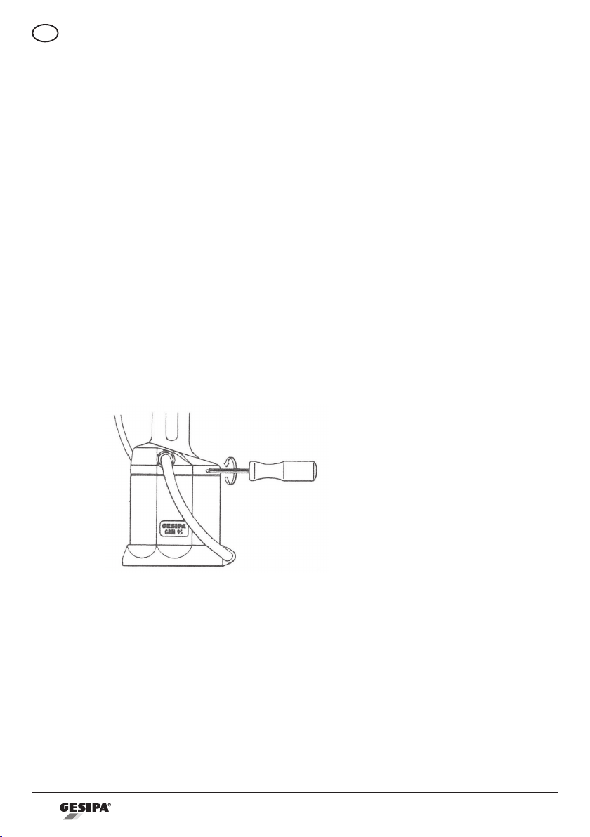
Gesipa GBM 95 User manual

GESIPA Blindniettechnik GmbH
Nordendstraße 13-39
64546 Mörfelden-Walldorf
Germany
GBM 95
T +49 (0) 6105 962 0
F +49 (0) 6105 962 287
www.gesipa.com


23
143 5243
24
145 7556
25
145 7553
26
145 7576
27
145 7577
28
145 7554
29
144 5813
30
145 7552
31
143 5160
32
143 5161
33
143 4221
34
145 7563
35
145 7567
36
143 4219
37
143 4216
38
145 6756
39
145 6758
40
143 5247
42
143 4220
43
144 5819
44
145 7559
45
144 5826
46
145 7555
47
145 7550
48
143 5179
49
143 4217
50
145 7549
51
143 5201
52
143 4224
53
145 7557
54
143 5204
55
143 4236
56
144 5292
57
143 4237
1
143 5213 M3
143 5214 M4 & 8-32“
143 5215 M5 & 10-32“
143 5216 M6
143 5217 M8 & 5/16-18“
143 5218 M10 & 3/8-16“
143 5148 1/4-20“
2
143 5207 M3
143 5208 M4
143 5209 M5
143 5210 M6
143 5211 M8
143 5212 M10
143 5149 8-32“
143 5143 10-32“
143 5144 1/4-20“
143 5150 5/16-18“
143 5145 3/8-16“
3
143 5185
4
143 5220
5
145 7574
6
143 4232
7
145 7560
8
145 6754
9
144 5265
10
145 7551
11
145 6749
12
145 7575
13
145 6752
14
143 4227
15
145 6757
16
145 7572
17
143 4226
18
145 7571
19
143 5237
20
143 5236
21
144 5823
22
145 7573

15
GB
Table of Contents
1. Use in accordance with the operating instructions ....................................16
2. Safety instructions .........................................................................................16
3. Working range ................................................................................................16
4. Technical data.................................................................................................16
5. Equipment and accessories..........................................................................17
6. Starting procedure .........................................................................................17
6.1 Adjustment of mandrel length "X"...............................................................17
6.2 Adjustment of stroke "Y".............................................................................18
6.3 Threading-on and setting of a blind rivet nut ..............................................19
6.4 Change of threaded mandrel .....................................................................20
6.5 Change of unthreading time .......................................................................20
7. Maintenance and service...............................................................................20
8. Repairs ............................................................................................................21
9. Environmental notes......................................................................................21
10. Troubleshooting .............................................................................................21
10.1 Rivet nut is not threading on .................................................................21
10.2 Set rivet nut is loose..............................................................................21
10.3 Threaded mandrel is not unthreading ..................................................21
11. Warranty ..........................................................................................................22
12. Conformity declaration ..................................................................................22

16
GB
1. Use in accordance with the operating instructions
The tool should be used only in accordance with these operating instructions for setting blind
rivet nuts.
The safety instructions must be followed!
2. Safety instructions
• The tool is to be used only for setting blind rivet nuts.
• Do not overload the tool. Work only within the indicated capability range.
• Do not operate the tool without installing a rivet nut.
• Regularly check compressed air connections with respect to tightness and leakage.
• Always disconnect the tool from compressed air supply when tool is not in use or when
servicing.
• When working with the tool, always wear protective safety glasses. Personal safety
equipment such as protective clothing, protective gloves, helmet, nonslip shoes and hea-
ring protection are recommended in order to safeguard against accidents.
• Keep long hair or loose clothing away from the tool during operation or when servicing.
• Repairs should be carried out by trained personnel only. If in doubt, return the tool to the
supplier.
• Used hydraulic oil must be disposed of in accordance with environmental regulations.
3. Working range
4. Technical data
Blind rivet nuts from M3 to M10, all materials.
Weight: 2.3 kg
Operating air pressure: 6 bar
Air connection: 6 mm Ø (1/4´´)
Air consumption: approx. 8 NI per cycle
Compressedairquality: lteredanddryed
Traction power: 15,700 N (1,600 kp)
Hydraulic oil: approx. 30 ml ISO VG 46
Noise emission: Lpa 82.5 dB, Measurement uncertainty K=3dB
Vibration: <2.5 m/s², Measurement uncertainty K=1.5 m/s²

17
GB
5. Equipment and accessories
Threaded mandrel and nosepieces: M6 in working position
Alternatively also M3, M4, M5, M8 and M10
Tools: Universal maintenance wrench MSU
Pin spanner Ø42
Hexagon screw driver SW 4 mm
Hexagon ball-end driver SW 2.5 mm
Other: Assembly rod
Hydraulicoilrellbottle
Operating manual with spare part list
6. Starting procedure
Before starting, carefully read and follow operating instructions!
6.1 Adjustment of mandrel length "X"
• Disconnect tool from compressed air to unlock the threaded mandrel.
• In case of standard blind rivets nuts «a» the protruding part of the threaded mandrel (2)
must be as long as the whole blind rivet nut (see drawing 1) and is hand adjusted by
turning the mandrel either in or out.
• In case of closed-end rivet nuts «b» use entire threaded depth.
• To lock the length adjustment connect tool to compressed air and the locking device is
engaged automatically.
Drawing 1
2
3
1

18
GB
6.2 Adjustment of stroke "Y"
The stroke «Y» (see chart) depends on the blind rivet nut size (M3 to M10, 6-32 to 3/8-16)
and the material thickness «Z» (drawing 2).
Stroke chart for GBM 95:
Thread size Stroke min. "Y" mm max.
M3 0.5 - 1
M4 1 - 2
M5 1.5 - 2.5
M6 2.5 - 3.5
M8 3.5 - 4.5
M10 3.5 - 4.5
• Loosen lock nut (3) (drawing 1).
• Adjust stroke «Y» by turning in or out the nosepiece (1).
• Stroke «Y» has to be adjusted to «min», to be locked (tightened) and then the rivet nut
has to be set.
• If the blind rivet nut does not form a proper sealing head (as shown in drawing 2) the stro-
ke «Y» must be increased step by step. Afters stroke adjustment, the lock nut (3) has to
be tightened.
Drawing 2

19
GB
6.3 Threading-on and setting of a blind rivet nut
• Place the rivet nut in front of the threaded mandrel (2) (see drawing 3) without tilting and
push the thread-on button (35).
• Holdtheblindrivetnutduringtheentirethreadingprocessuntilittstightlyagainstthe
nosepiece (1).
• Insert the blind rivet nut into the workpiece, ensuring that the fastener´s head is fully sea-
ted. Next set the blind rivet nut by pressing the stroke button (35).
• Hold button (35) until blind rivet nut is set completely.
• Release button (35). The threaded mandrel (2) is threaded off automatically.
Drawing 3
Attention!
In order to avoid upsetting smaller or thin-wall type blind rivet nuts during the threa-
ding process, disconnect tool and increase the threaded mandrel protusion to a length
suchthattherivetnutdoesnotthreadonushagainstthenosepiece.Adjustsetting
stroke (see paragraph 6.2)
Important:
• If the threaded mandrel (2) is not threaded out of the blind rivet nut completely, a short
quick touch of the stroke button (35) will induce threading-out procedure.
• If the threaded mandrel is stuck in the blind rivet nut, it may be loosened by means of the
enclosed hexagon wrench SW4 (see drawing 4).
Drawing 4
35
35
2 1

20
GB
7. Maintenance and service
Special maintenance is not necessary. If applicable, exchange worn threaded mandrels ac-
cording to paragraph 6.4. When not in use the tool should be kept in a dry room.
6.4 Change of threaded mandrel
• Disconnect tool from compressed air supply.
• Loosen lock nut (3) (drawing 1).
• Unscrew nosepiece (1).
• Unscrew threaded mandrel (2) by turning backward and forward until mandrel releases.
• Screw in new threaded mandrel.
• Screw in corresponding nosepiece (1) with lock nut (3).
• Adjust setting stroke «Y» and length of threaded mandrel «X» (see paragraphs 6.1 and
6.2).
6.5 Change of unthreading time
• The adjusting screw at the edge of the handle near the air connection can be reached
with enclosed ball-headed screw driver SW 2.5 mm (see drawing 5).
• A slight turn to the right increases the unthreading time.
• A slight turn to the left reduces the unthreading time.
Drawing 5

21
GB
8. Repairs
Repairs under warranty are carried out by the manufacturer. Repairs outside the warranty pe-
riod should only be carried out by skilled technical personnel. Failure to observe the assembly
and setting procedures and operation by non-skilled personnel may result in serious damage
to the blind rivet setting tool. In case of doubt, always send the blind rivet setting tool back to
the supplier or to GESIPA®.
9. Environmental notes
Used hydraulic oil must be disposed of in accordance with recycling regulations.
10. Troubleshooting
10.1 Rivet nut is not threading on
Cause Solution
Faulty rivet nut thread Use new rivet nut
Faulty mandrel thread
Exchange threaded mandrel (see para-
graph 6.4)
Hold rivet nut tightly when threading out
10.2 Set rivet nut is loose
Cause Solution
Setting stroke „Y“ too short Adjust to larger stroke (see paragraph 6.2)
10.3 Threaded mandrel is not unthreading
Cause Solution
Setting stroke „Y“ too long
Reduce stroke (see paragraph 6.2)
If necessary, unscrew with hexagon screw
driver (see drawing 4)
Threading-on time too short Increase threading-on period (see para-
graph 6.5)

22
GB
11. Warranty
The applicable terms and conditions of warranty shall apply and can be viewed under fol-
lowing link: www.gesipa.com/agb
12. Conformity declaration
ppa. Dr. Richard Gärtner
We hereby declare that the design and construction of the tool named below, as well as the
version that we have put on the market, complies with applicable fundamental health and
safetyrequirementsstipulatedinEUdirectives.Toolmodicationsmadewithoutourauthori-
sation shall render this declaration void. The safety information in the product documentation
provided must be observed. This document must be retained.
GBM 95
•DIN EN ISO 12100:2011
•DIN EN ISO 11148-1:2012
•DIN EN 82079-1:2013
Authorised documentation representative:
GESIPA Blindniettechnik GmbH
Nordendstraße 13-39
D-64546 Mörfelden-Walldorf

08/2017 - 1431959
Other manuals for GBM 95
1
Table of contents
Other Gesipa Rivet Tools manuals

Gesipa
Gesipa AccuBird Pro Guide

Gesipa
Gesipa FireFox 2 User manual

Gesipa
Gesipa taurus 1 Guide

Gesipa
Gesipa FireBird Pro User manual

Gesipa
Gesipa PH 2000 Guide

Gesipa
Gesipa PowerBird Pro Gold Edition Guide

Gesipa
Gesipa FireBird Gold Edition User manual

Gesipa
Gesipa AccuBird Pro Guide

Gesipa
Gesipa PowerBird Guide

Gesipa
Gesipa AccuBird Guide

Gesipa
Gesipa PH 1 Guide

Gesipa
Gesipa FireRex C-WT Guide

Gesipa
Gesipa TAUREX 1 Axial User manual

Gesipa
Gesipa taurus 3 Setup guide

Gesipa
Gesipa AccuBird Pro User manual

Gesipa
Gesipa PowerBird Pro Gold Edition Guide

Gesipa
Gesipa AccuBird Guide

Gesipa
Gesipa PowerBird Pro Guide

Gesipa
Gesipa Bird Series Operating instructions

Gesipa
Gesipa taurus 1 Guide