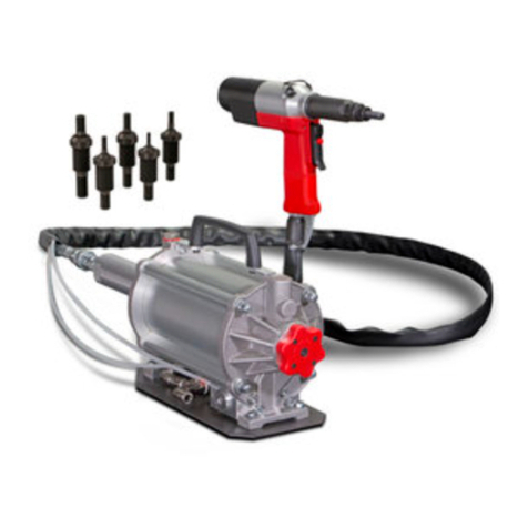
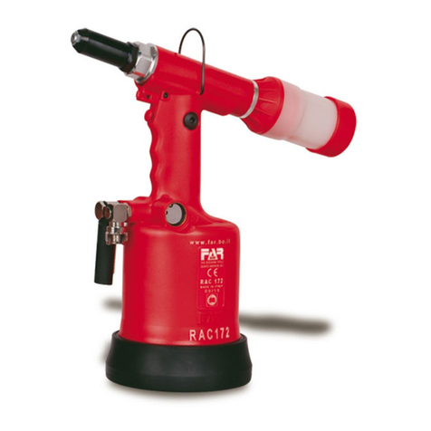
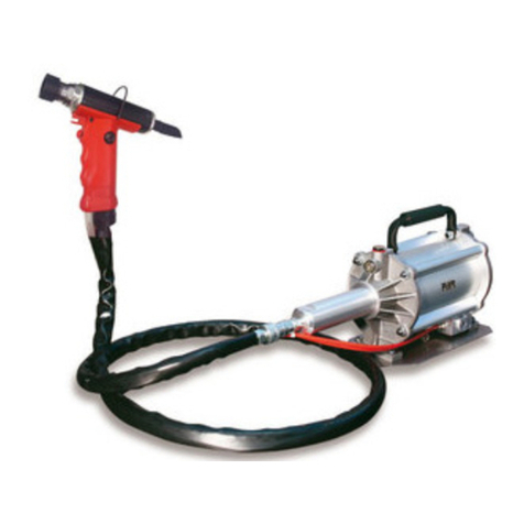
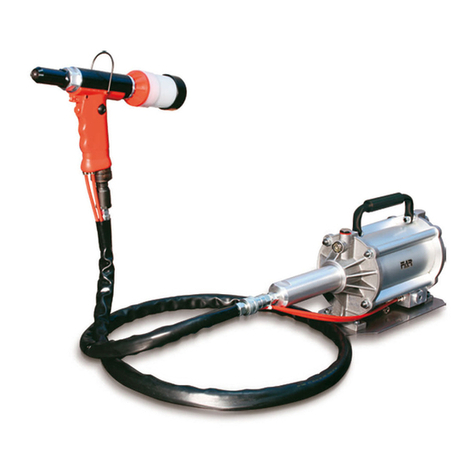
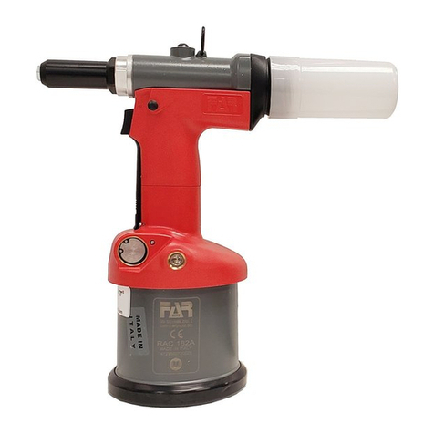
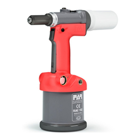
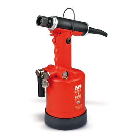
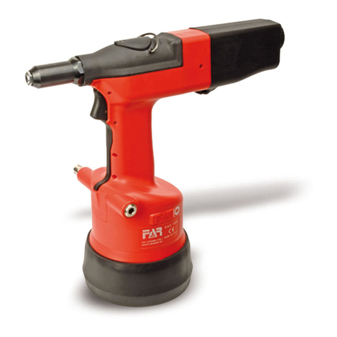
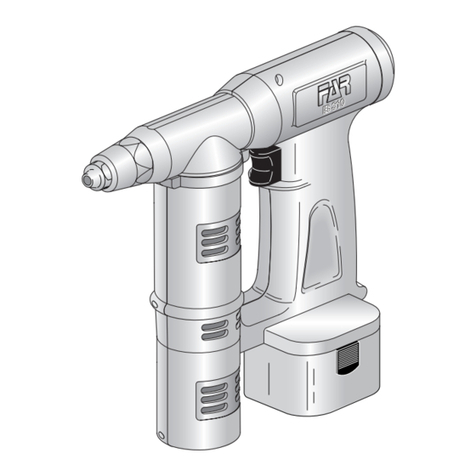
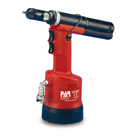
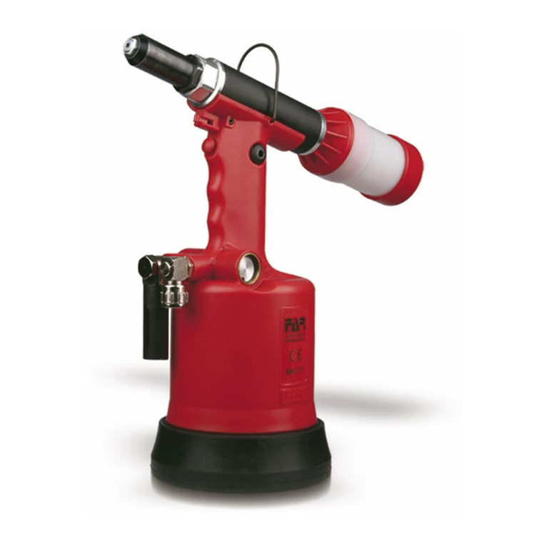
FAR KJ 60-A Setup guide

KJ 60-A
KJ 60-A
- ISTRUZIONI ORIGINALI
RIVETTATRICE OLEOPNEUMATICA
PER INSERTI 6-32 ÷ 5/16"-18*
(*ESCLUSO 5/16"-18 INOX )
ISTRUZIONI D’USO - PARTI DI RICAMBIO
- TRANSLATION OF ORIGINAL INSTRUCTIONS
HYDROPNEUMATIC RIVETING TOOL
FOR INSERTS 6-32 ÷ 5/16"-18*
(*INOX 5/16"-18 EXCLUDED )
INSTRUCTIONS FOR USE - SPARE PARTS
I
GB

KJ 60-A
Far S.r.l. - Massimo Generali
(Presidente del Consiglio di Amministrazione)
(Chairman of the Board of Directors)
(Président du Conseil d’Administration)
(Vorsitzender des Verwaltungsrates)
(Presidente del Consejo de Administración)
(Prezes Zarzadu)
.............................................
La sottoscritta Far S.r.l., con sede in Quarto Inferiore (BO) alla via Giovanni XXIII n° 2,
DICHIARA
sotto la propria esclusiva responsabilità che la rivettatrice Modello: KJ 60-A - Rivettatrice oleopneumatica
Utilizzo: per inserti filettati 6-32 ÷ 5/16"-18
(escluso
5/16"-18
Inox)
, Numero di serie: vedi retro copertina, alla quale questa
dichiarazione si riferisce è conforme ai requisiti essenziali di sicurezzadella “Direttiva Macchine 2006/42/CE (e successive
modificazioni ed integrazioni)” e “Supply of Machinery (Safety) Regulations 2008 – UK SI 2008 No. 1597”. La persona
autorizzata a costituire il fascicolo tecnico risponde al nome di Massimo Generali, presso la Far S.r.l.,
con sede in Quarto Inferiore (BO) alla via Giovanni XXIII n° 2.
The undersigned Far S.r.l., having its office in Quarto Inferiore (BO), Via Giovanni XXIII No. 2, herewith
DECLARES
on its sole responsability that the riveting machine Type: KJ 60-A - Hydropneumatic tool
Application: for threaded inserts 6-32 ÷ 5/16"-18
(Inox
5/16"-18
excluded)
, Serial number: see back cover which is the
object of this declaration complies with the basic safety requirements estabilished in the “Machinery Directive 2006/42/CE
acknowledge (and subsequent amendments and integrations)” and “Supply of Machinery (Safety) Regulations 2008 – UK
SI 2008 No. 1597”.
The person who is authorized to create the technical brochure is Massimo Generali, c/o Far S.r.l.,
head office in Quarto Inferiore (BO), via Giovanni XXIII n. 2.
Quarto Inferiore, 31-12-2020
I
GB

I
I
ISTRUZIONI D’USO.................................................4
INSTRUCTIONS FOR USE.......................................9
PARTI DI RICAMBIO .............................................14
SPARE PARTS.......................................................15
KJ 60-A
GB
GB

IKJ 60-A
4Date 09-2022 Revisione - 02
ISTRUZIONI D’USO
INDICE
GARANZIA E ASSISTENZA TECNICA.....................................4
AVVERTENZE E MISURE DI SICUREZZA...............................4
IDENTIFICAZIONE DELLA RIVETTATRICE .............................5
NOTE GENERALI E CAMPO DI APPLICAZIONE.....................5
PARTI PRINCIPALI................................................................5
DATI TECNICI........................................................................5
POSA IN OPERA DELL’INSERTO...........................................6
CAMBIO DI FORMATO ..........................................................7
RABBOCCO OLIO CIRCUITO OLEODINAMICO ......................8
SMALTIMENTO DELLA RIVETTATRICE .................................8
ATTENZIONE!!!
La mancata osservanza o trascuratezza delle seguenti
avvertenze di sicurezza può avere conseguenze sulla
vostra o altrui incolumità e sul buon funzionamento
dell’utensile.
•Leggereattentamenteleistruzioniprimadell’uso.
•Perleoperazionidimanutenzionee/oriparazioneaffidarsi
a centri di assistenza autorizzati dalla FAR s.r.l. e fare uso
esclusivo di pezzi di ricambio originali. La FAR s.r.l. declina
ogni responsabilità per danni da particolari difettosi, che
si dovessero verificare per inadempienza di quanto sopra
(Direttiva CEE 85/374).
L’ELENCO DEI CENTRI DI ASSISTENZA È DISPONIBILE SUL
NS. SITO WEB: http://www.far.bo.it ( Organizzazione )
•Si raccomandal’usodell’utensiledapartedipersonale
specializzato.
•Durantel’impiegodell’utensile,usareocchialiovisiere
protettive e guanti.
•Perleoperazionidicaricaolio,usaresolofluidicon
caratteristiche indicate nel presente fascicolo.
•Incasodiperditeaccidentalidioliochedovesserovenire
a contatto con la pelle, lavarsi accuratamente con acqua e
sapone alcalino.
•L’utensilepuòesseretrasportatoamanoedèconsigliabile,
dopo l’uso, riporlo nel proprio imballo.
ATTENZIONE! Prima di utilizzare la rivettatrice, montare
il fondello di protezione in dotazione, come evidenziato
nella figura a lato.
FAR declina ogni responsabilità per eventuali danni alla
rivettatrice, persone o cose causati dalla mancata presenza
del fondello.
GARANZIA E ASSISTENZA TECNICA
Le rivettatrici FAR sono coperte da garanzia di 12 mesi.
Il periodo di garanzia dell'attrezzo decorre dal momento
della sua comprovata ricezione da parte dell'acquirente. La
garanzia copre l'utente/acquirente quando l'attrezzo viene
acquistatoattraverso un rivenditoreautorizzato esolo quando
viene impiegato per gli usi per i quali è stato concepito. La
garanzia non è valida se l'attrezzo non viene utilizzato e se
non viene sottoposto a manutenzione come specificato nel
manuale di istruzione e manutenzione. In caso di difetti o
guasti la FAR S.r.l. si impegna unicamente a riparare e/o
sostituire, a propria discrezione esclusiva, i componenti
giudicati difettosi.
AVVERTENZE E MISURE Dl SICUREZZA
• Si consigliaaifinidiuncorrettofunzionamentodella
rivettatrice, una revisione semestrale.
• Gliinterventidiriparazioneepuliziadell’utensiledovranno
essere eseguiti con macchina non alimentata dall’aria
compressa.
• È consigliabile,ovepossibile,I’usodiunbilanciatoredi
sicurezza.
• Incasodiesposizionequotidianapersonaleinambienteil
cui livello di pressione acustica dell’emissione ponderata
A sia superiore al limite di sicurezza di 70 dB (A), fare uso
di adeguati mezzi individuali di protezione dell’udito (cuffia
o tappo antirumore, diminuzione del tempo di esposizione
quotidiana etc...).
• Mantenereilbancoe/ol’areadilavoropulitaeordinata,il
disordine può causare danni alla persona.
• Nonlasciarechepersoneestraneeallavorotocchinogli
utensili.
• Assicurarsicheitubidialimentazionedell’ariacompressa
siano correttamente dimensionati per l’uso previsto.
• Nontrascinarel’utensilecollegatoall’alimentazionetirandolo
per il tubo; mantenere quest’ultimo lontano da fonti di calore
e da oggetti taglienti.
• Manteneregliutensiliinbuonostatod’usoepuliti,non
rimuovere mai le protezioni e il silenziatore dell’utensile.
•Dopoavereeseguitooperazionidiriparazionee/o
registrazione assicurarsi di avere rimosso le chiavi di servizio
o di registrazione.
•Primadiscollegareiltubodialimentazionedell’aria
compressa dalla rivettatrice, assicurarsi che quest’ultimo
non sia in pressione.
• Attenersiscrupolosamenteaquesteistruzioni.
KJ 60 A
5
I
KJ 60-A
Revisione - 02 Date 09-2022
IDENTIFICAZIONE DELLA RIVETTATRICE
La rivettatrice KJ 60-A è identificata da una marcatura indicante
ragione sociale e indirizzo, designazione della macchina ,
marcatura CE. In caso di richiesta di assistenza tecnica fare
sempre riferimento ai dati riportati nella marcatura.
NOTE GENERALI E CAMPO DI APPLICAZIONE
L’uso dell’utensile è finalizzato esclusivamente all’utilizzo di
inserti filettati con filetto compreso tra 6-32 ÷ 5/16"-18.
Il sistema oleopneumatico utilizzato dalla rivettatrice KJ 60-A
fornisce una maggior potenza rispetto al tradizionale sistema
pneumatico su cui si basano altri modelli di rivettatrici. Ciò
significa una drastica riduzione dei problemi dovuti all’usura dei
componenti con conseguente aumento di affidabilità e durata.
Le soluzioni tecniche adottate riducono le dimensioni e il peso
della macchina rendendo la rivettatrice KJ 60-A assolutamente
maneggevole.Lapossibilità diperditedal sistemaoleodinamico
sonopreclusedall’impiego diguarnizionia tenutacheeliminano
questo problema.
DATI TECNICI
• Pressionediesercizio ................................................6 BAR
• Diametrointernominimotuboalimentazione
aria compressa .......................................................... 8 mm
• Consumomaxarialibera,perciclo...............................9 Nl
• Forzamassima......................................... 6 BAR - 13656 N
• Peso......................................................................2,212 Kg
• Temperaturadiutilizzo........................................-5°/+50 C°
• Valoremedioquadraticoponderatoin
frequenza dell’accelerazione complessiva (Ac)
a cui sono sottoposte gli arti superiori................ < 2,5 m/s2
• Pressioneacusticadell’emissioneponderata(A)..... 70 dBA
• Pressioneacusticaistantaneaponderata(C) ...... < 130 dBC
• Potenzaacusticaponderata(A) ............................... 82 dBA
PARTI PRINCIPALI
A).................................................................... Tirante filettato
B).................................................................................Testina
C)....................................................Ghiera bloccaggio testina
D).............................................................Pulsante di trazione
E) ........................................................Pulsante di svitamento
F) .......................Foro inserimento spina sbloccaggio innesto
G).................................................Ghiera di regolazione corsa
H).............................................................Attacco bilanciatore
I)..............................................................Motore pneumatico
L) ............................................................Tappo serbatoio olio
M)........................................... Allacciamento aria compressa
N).........................................................Fondello di protezione
KJ 60-A
KJ 60-A
Ragione sociale e indirizzo
del fabbricante
Designazione macchina
ALIMENTAZIONE DELL’ARIA
L’aria di alimentazione deve essere libera da corpi estranei e da
umidità per proteggere la macchina da usura precoce
delle parti in movimento; è consigliabile, pertanto, l’impiego di
un gruppo lubrificatore per aria compressa.
Numero di serie
KJ 60-A
E
A
B
C
M
D
N
FGHI
L
295
80
270
Ø 35
Ø 109
Ø 24

IKJ 60-A
6Date 09-2022 Revisione - 02
ATTENZIONE!!! LA REGOLAZIONE NON CORRETTA DELLA CORSA DELLA RIVETTATRICE
PUÒ CAUSARE IL CATTIVO SERRAGGIO DEGLI INSERTI E LA ROTTURA DEL TIRANTE!
POSA IN OPERA DELL’INSERTO
Verificare che la coppia tirante-testina montata sulla rivettatrice sia adeguata alla misura dell’inserto che si vuole serrare; in caso
contrario procedere al cambio di formato. Solitamente la coppia tirante-testina montata sulla rivettatrice in confezione corrisponde
ad una filettatura di 6-32 UNC. Prima di utilizzare la rivettatrice e dopo ogni cambio di formato occorre eseguire le seguenti
operazioni in funzione del formato e dello spessore del materiale da serrare:
Regolare la corsa della rivettatrice al minimo, ruotando per quanto possibile la ghiera “G” nel senso indicato dal simbolo “–”.
Inserire l’inserto sul tirante ed esercitare su di esso una leggera pressione; in questo modo l’inserto si avvita automaticamente sul
tirante. Assicurarsi che la testa dell’inserto vada in battuta con la testina della rivettatrice. Fissare l’inserto e verificare il serraggio
che questo opera sullo spessore del materiale. Regolare la corsa della rivettatrice mediante la rotazione della ghiera “G”, in
funzione del serraggio desiderato, considerando che all’aumentare della corsa (rotazione della ghiera “G” nel senso indicato dal
simbolo “+”) la distanza “h” tra testa e deformazione dell’inserto diminuisce con conseguente aumento dell’azione di serraggio.
+
–
H
H
G

7
I
KJ 60-A
Revisione - 02 Date 09-2022
CAMBIO DI FORMATO
Al variare della filettatura degli inserti da serrare, occorre eseguire la sostituzione della coppia Tirante/testina, pertanto procedere
come segue:
FIG. 1. Allentare la ghiera con una chiave commerciale di mm 25 e rimuovere la testina.
FIG. 2. Fare passare la spina (in dotazione) attraverso l’apposito foro di servizio,situato nel canotto porta testina, ed esercitare
su di essa una pressione verso l’interno in modo da sbloccare l’innesto dal tirante. Contemporaneamente svitare il tirante ed
estrarlo leggermente.
FIG. 3-4. Mantenendo sbloccato l’innesto avvitare il formato di tirante desiderato. Completata la sostituzione del Tirante ruotarlo
leggermente fino a che non si avverte lo scatto d’innesto, procedere quindi al montaggio della relativa testina bloccandola con
l’apposita ghiera allentata in precedenza. Ogni volta che si effettua il cambio di formato ripetere le operazioni di registrazione
riportate nelle pagine precedenti.
ATTENZIONE! LE OPERAZIONI SOPRAELENCATE DEVONO ESSERE ESEGUITE CON MACCHINA NON ALIMENTATA.
1
3
2
4
25 mm.
25 mm.
Click!

I
8Date 09-2022 Revisione - 02
KJ 60-A
RABBOCCO OLIO CIRCUITO OLEODINAMICO
Il rabbocco dell’olio del circuito oleodinamico si rende necessario dopo un lungo periodo di lavoro, quando si avverte un calo di corsa della
rivettatrice. Procedere quindi come segue: con rivettatrice in sosta e non alimentata, tenuta in posizione orizzontale, rimuovere il tappo
(A) servendosi della chiave a brugola di mm 5 (in dotazione), durante questa operazione prestare la massima attenzione per
evitare fuoriuscite di olio. Avvitare nella sede del tappo (A) il contenitore a soffietto (X) preventivamente riempito con olio idraulico
commerciale HLP 32 cSt .
Mantenendo la rivettatrice orizzontale, attivare l’alimentazione dell’aria, premere il pulsante di trazione facendo compiere alla
rivettatrice una serie di cicli fino a quando non sia completamente cessata l’emissione di bolle d’aria all’interno del contenitore (X),
questa condizione sta a significare che il rabbocco dell’olio è completato. A questo punto disattivare l’alimentazione dell’aria e, con
rivettarice sempre orizzontale, svitare il contenitore olio (X) e richiuderlo. Procedere quindi alla chiusura del tappo (A).
CAUTELA: è di estrema importanza attenersi alle istruzioni sopra indicate ed effettuare le operazioni di rabbocco olio muniti di guanti.
Nel caso di svuotamento completo del circuito idraulico, recuperare tutto l’olio in un apposito contenitore e avvalersi sucessivamente
di una ditta autorizzata allo smaltimento dei rifiuti.
ATTENZIONE! Prima di scollegare il tubo dell’aria compressa dalla rivettatrice accertarsi
che quest’ultimo non sia in pressione!
Si raccomanda l’uso di olio HLP 32 cSt o simili.
IIMPORTANTE: Assicurarsi che il tappo di
rabbocco olio (A) venga serrato con una
coppia pari a: min. 5 Nm ÷ Max. 8 Nm.
A
X
5 mm.
min. 5 Nm
MAX. 8 Nm
SMALTIMENTO DELLA RIVETTATRICE
Per lo smaltimento della rivettatrice attenersi alle prescrizioni imposte dalle leggi nazionali.
Dopo aver scollegato la macchina dall’impianto pneumatico, procedere allo smontaggio dei vari componenti
suddividendoli in funzione della loro tipologia: acciaio, alluminio, materiale plastico, ecc.
Procedere quindi alla rottamazione nel rispetto delle leggi vigenti.

9Revisione - 02 Date 09-2022
KJ 60-A
INSTRUCTIONS FOR USE I
INDEX
GUARANTEE AND TECHNICAL ASSISTANCE.............................. 9
SAFETY MEASURES AND REQUIREMENTS ............................... 9
TOOL IDENTIFICATION ............................................................. 10
GENERAL NOTES AND USE ...................................................... 10
MAIN COMPONENTS ................................................................ 10
TECHNICAL DATA ..................................................................... 10
PLACING OF THE INSERT......................................................... 11
CHANGE OF SIZE ..................................................................... 12
TOOPING UP THE OIL-DYNAMIC CIRCUIT ............................... 13
DISPOSAL OF THE RIVETING TOOL ......................................... 13
CAUTION!!!
All the operations must be done in conformity with the
safety requirements, in order to avoid any consequence
for your and other people security and to allow the best
tool work way.
•Readtheinstructionscarefullybeforeusingthetool.
•Forallmaintenanceand/orrepairspleasecontactFAR s.r.l.
authorized service centers and use only original spare parts.
FAR s.r.l. may not be held liable for damages from defective parts
caused by failure to observe what mentioned above (EEC directive
85/374).
The list of the service centres is available on our website
http://www.far.bo.it ( Organization )
•Thetoolmustbeusedonlybyexpertworkers.
•Aprotectivevisorandglovesmustbeputonwhenusingthe
tool.
•Fortoppinguptheoil,wesuggestusingonlyfluidsinaccordance
with the features specified in this working book.
•Ifanydropofoiltouchesyourskin,youmustwashwithwater
and alkaline soap.
•Thetoolcanbecarriedandwesuggestputtingitintoitsbox
after using.
•Thetoolneedsathoroughsix-monthlyoverhaul.
GUARANTEE AND TECHNICAL ASSISTANCE
FAR riveting tools are covered by a 12-month warranty. The
tool warranty period starts on the date of delivery to the
buyer, as specified in the relevant document. The warranty
covers the user/buyer provided that the tool is purchased
through an authorized dealer and only if it is used for the
purposes for which it was conceived. The warranty shall
not be valid if the tool is not used or maintained as specified
in the instruction and maintenance handbook. In the event
of defects or failures, FAR S.r.l. shall undertake solely to
repair and/or replace the components it judges to be faulty.
SAFETY MEASURES AND REQUIREMENTS
• Repairingandcleaningoperationsmustbedonewhenthetool
is not fed.
• Asafetybalancerissuggestedwhenitispossible.
• IftheA-weightedemissionsoundpressurelevelismorethan
70 dB (A), you must use some hearing protections (anti-noise
headset, etc.).
• Theworkbenchandtheworksurfacemustbealwayscleanand
tidy. The untidy can cause damages to people.
• Donotallowunauthorizedpersonstousetheworkingtools.
• Makeyousurethatthecompressedairfeedinghoseshavethe
correct size to be used.
• Donotcarrytheconnectedtoolbypullingthehose.Thehole
must be far from any heating sources or from cutting parts.
• Keepthetoolsingoodconditions;donotremoveeithersafety
parts or silencers.
• Afterrepairingand/oradjusting,makesureyouhavealready
removed the adjusting spanners.
• Beforedisconnectingthecompressedairhosefromthetool
make sure that there is no pressure in the hose.
• Theseinstructionsmustbecarefullyfollowed.
WARNING! Before using the tool, assemble the protection
bottom supplied with the tool, as indicated in the picture
on side.
FAR has no responsibility for any damages on the tool,
persons or things caused by lack of the protection bottom.
KJ 60 A
GB

GB
10 Date 09-2022 Revisione - 02
KJ 60-A
TOOL IDENTIFICATION
The riveting tool KJ60-Ais identified from a marking that shows
company name and address of manufacturer, designation of
the tool, CE. Always refer to the information on the riveting tool
when requesting technical service.
GENERAL NOTES AND USE
The tool can be employed only for threaded inserts with thread
of 6-32 ÷ 5/16"-18 diameter.
The KJ 60-A oil pneumatic system assures more power than
the pneumatic system used for other models. That means
a reduction in the problems due to the wear and tear of the
components, therefore, there will be an increase in reliability.
The technicai solutions adopted reduce the dimensions and the
weight of the tooi which, for these reasons, make it very handy.
The possibilities of leakage from the oil-dynamic system, are
eliminated by some sealed gaskets, which solve this problem.
TECHNICAL DATA
• Workingpressure ......................................................87 psi
• Min.int.diam.ofthecompressedair
feeding hose .......................................................... 0.315"
• Airconsumptionpercycle ....................................5.492i n³
• Maxpower................................................ 87 psi - 3070 lbf
• Weight ....................................................................... 4.9 lb
• Workingtemperature...................................... -23°F/+122°F
• Rootmeansquareintotalaccelerationfrequency(Ac)
to which the arms are subjected...................... < 98.42 ips²
• A-weightedemissionsoundpressurelevel............. 70 dBA
• PeakC-weightedinstantaneoussoundpressure<130 dBC
• A-weightedsoundpower........................................ 82 dBA
MAIN COMPONENTS
A) .................................................................Threaded tie rod
B) ...................................................................................Head
C) ..................................................... Ring nut clamping head
D) ...............................................Tensile strength pushbutton
E) .....................................................Unscrewing pushbutton
F) ................................ Insertion Pin Hole Dechucking clutch
G) ..................................................Regulation stroke ring nut
H)........................................................... Balancer connection
I) .................................................................. Pneumatic motor
L) .......................................................................Oil tank plug
M) .............................................. Compressed air connection
N)............................................................... Protection bottom
KJ 60-A
KJ 60-A
KJ 60-A
E
A
B
C
M
D
N
FGHI
L
11.6"
3.1"
11.3"
Ø 1.4"
Ø 4.3"
Ø 0.9"
AIR FEED
The air feed must be free from foreign bodies and humidity in
order to protect the tool from premature wear and tear
of the components in movement, therefore we suggest to use
a lubrificator group for compressed air.
Company name and
address
Designation of the tool
Serial number

11
GB
Revisione - 02 Date 09-2022
KJ 60-A
WARNING!!! A WRONG ADJUSTMENT OF THE RIVETING TOOL STROKE
MAY CAUSE A FAULTY CLAMPING OF INSERTS AND MAY BRAKE THE TIE ROD!
PLACING OF THE INSERT
Make sure that the couple tie-rod/head mounted on your riveting tool is suitable for the insert to clamp; otherwise, change size
accordingly. Usually the riveting tool is supplied with the couple tie-rod/head corresponding to a 6-32 UNC thread. Before using
the riveting tool and after any change of size, perform the following operations according to the size and thickness of the part to
clamp. Adjust the riveting tool stroke to the minimum by turning the ring nut “G” to “–” marked on the tool. Place the insert on
the tie rod and push slightly on it so as to make it clamp automatically. Make sure the insert head touches the riveting tool head
properly. Fasten the insert and in order to ensure a proper clamping of the material, adjust the riveting tool stroke by turning the
ring nut “G” accordingly. By increasing stroke, i.e. by turning the ring nut “G” to “+”, the distance “h” between head and insert
deformation will decrease and clamping will result more effective.
+
–
H
H
G

GB
12 Date 09-2022 Revisione - 02
KJ 60-A
CHANGE OF SIZE
Depending on insert thread, it is necessary to replace the couple “tie-rod/head” as follows:
PICTURE 1. Loosen the ring nut by means of a 25 mm standard spanner and remove the riveting tool head.
PICTURE 2. Make the pin supplied pass through the pertinent service hole located on the cone carrying head and apply a light
pressure on the head inwards, in order to dechuck the tie rod clutch., at the same time, unscrew the tie rod and extract it.
PICTURE 3-4.Keeptheclutchdechuckedandscrewthetierodsizedesired.Whenthereplacementofthetierodhasbeen
performed, swing it until you hear a click. Them assembly the proper head and lock it with the corresponding ring nut loosen
before. Each time you carry out any change of size, repeat the adjustment operations as specified in the previous pages.
WARNING! DESCONNECT AIR FEED WHEN PERFORMING THOSE OPERATIONS.
1
3
2
4
25 mm
Click!
25 mm

13
GB
Revisione - 02 Date 09-2022
KJ 60-A
TOPPING UP THE OIL-DYNAMIC CIRCUIT
You need to top up the oil-dynamic circuit after a long period of work, when you note a power loss. Put the riveting tool (DWELL
AND NOT FED) in a horizontal position and remove the plug (A), by means of a 5 mm Allen wrench (equipped with the riveting
tool); during this operation, check the oil level in order to avoid any overflowing. Then, slowly pour the oil HLP 32 cSt into the
bellows container (X) which shall be screwed to its seat on the plug (A).Whilekeepingtherivetingtoolinahorizontalpositionand
starting air feeding, push the tensile strength button and make the riveting tool carry out some cycles until air bubbles inside the
container (X) stop coming out. This condition indicates that the topping up of the oil has fully been achieved. At this point stop the
air feeding and, while keeping the riveting tool in a horizontal position, unscrew and close up the container (X) and the plug (A).
WARNING: it is very important to follow the about mentioned instructions and use gloves. If you need to empty fully the hydraulic
circuit, you must put the oil in a suitable container and contact a Company that is authorized to discharge any waste
WARNING! Before disconnecting the compressed air hose, make sure that it is not under pressure!
We recommend to use oil HLP 32 cSt or similars.
WARNING: Make sure that the oil filler cap
(A) is tightened at a torque corresponding
to min. 3.69 ÷ Max. 5.90 ftlb.
A
X
min. 3.69 ftlb
Max. 5.90 ftlb
5 mm
DISPOSAL OF THE RIVETING TOOL
Follow the prescriptions of the national laws for disposing of the riveting tool.
After disconnecting the tool from the pneumatic system, disassemble and split all the components according
to the material: steel, aluminium, plastic material, etc.
Then proceed to scrap the materials in accordance with current laws.
GB

14 Date 09-2022 Revisione - 02
KJ 60-A
I
N° COD. Qt. DESCRIZIONE KIT N° COD. Qt. DESCRIZIONE KIT
74 711092 1 Chiave a brugola 5 mm
75 711728 2 Guarnizione OR 2-016
76 711730 1 Guarnizione OR 2-119
77 710367 1 Guarnizione OR 2-008
78 710376 2 Guarnizione OR 2-009
79 710918 2 Guarnizione OR 2-005
80 710919 2 Guarnizione OR 2-004
81 710003 2 Guarnizione OR 5-052
82 710342 2 Guarnizione OR 2-017
83 710594 1 Guarnizione OR 2-012
84 711061 1 Guarnizione OR 5-614
85 711731 1 Guarnizione OR 2-018
86 711732 1 Guarnizione OR 2-118
87 710258 3 Guarnizione OR 5-612
88 711734 1 Guarnizione OR 2-232
89 711735 1 Guarnizione OR 2-040
90 711834 2 Silenziatore
91 711917 1 Anello Parbak 8-119
92B 711933 1 Anello Seeger JV 24 B
95 712159 1 Fondello di protezione
96 722047 1 Struttura valvola sicurezza
97 712153 1 Molla premi asta
98 712132 1 Raccordo girevole
99E 713341 1 Guarnizione OR 1x 4 E
100 711881 1 Tirante 10-32 UNF
KIT Indica che il particolare viene venduto in Kit composti da
particolari diversi in quantità diverse.
01 721779 1 Corpo rivettatrice
02 712269 1 Coperchio corpo
03 711684 1 Fondello cilindro
04 721685 1 Pistone pneumatico
05 711780 1 Raccordo
06 721689 1 Cilindro Oleodinamico
07 711781 1 Stelo
08 711691 1 Silenziatore
09 711692 1 Vite TE M7 x 18
10 711782 1 Ammortizzatore
11 711694 1 Spoletta inferiore
12 711695 1 Cannotto lettato
13 721698 1 Corpo valvola
14 711700 1 Spoletta superiore
15 711701 1 Corpo valvola superiore
16A 711702 1 Piastrina zincata A
17 711703 2 Corpo valvolina
18 711704 2 Pistoncino valvola
19 710839 1 Tappo serbatoio olio
20D 711705 2 Pulsante D
21B 711713 1 Distanziale B
22 710854 1 Gancio bilanciatore
23 721387 1 Contenitore olio
24 711783 1 Coperchio motorino
25
72A00126
1 Motore pneumatico F002
26 711785 1 Settore protezione motore
27 711786 1 Ghiera
28 711787 1 Anello di arresto
29 712670 1 Innesto composto
30 711790 1 Molla ritorno pistone
31 711791 1 Molla bloccaggio sfere
32E 711792 1 Bussola porta sfere E
33 712270 1 Asta
34 711794 1 Pistone oleodinamico
35 711795 1 Raccordo anteriore
36 711796 1 Albero
37 711797 1 Cannotto fresato
38 711798 1 Ghiera
39 711799 1 Pomello regolazione corsa
40C 711800 1 Molla disinnesto tirante C
41 711801 1 Cannotto porta tirante
42C 711802 1 Innesto per tirante C
43 711803 1 Ghiera
44 711804 1 Ghiera
45 711884 1 Testina 5/16"-18 UNC
46 711885 1 Testina 1/4"-20 UNC
47 711888 1 Testina 8-32 UNC
48 711886 2 Testina 10-24 UNC 10-32 UNF
49 711887 1 Testina 6-32 UNC
50 711878 1 Tirante 5/16"-18 UNC
51 711879 1 Tirante 1/4"-20 UNC
52 711883 1 Tirante 8-32 UNC
53 711880 1 Tirante 10-24 UNC
54 711882 1 Tirante 6-32 UNC
55 710876 1 Spina disinnesto tirante
56 710906 1 Rondella 400-020-4490
59D 711726 3 Spina cilindrica ø 2 x 20 UNI 1707 D
60C 710537 1 Spina elastica ø 4 x 12 UNI 6873 C
61 711815 2 Sfera ø 3,5
62 710911 4 Sfera ø 4
63E 711816 3 Sfera ø 2,5 E
64 711817 1 Anello Seeger 18 UNI 7437
65B 710902 1 Anello Seeger 16 UNI 7435 B
66 711818 1 Anello Seeger SW 11
67 711821 1 Anello Seeger JV 20
68 711721 1 Guarnizione B-110078/B/NEO
69 711722 1 Guarnizione B-094063/B/NEI
70 711819 1 Guarnizione B-070039 / 1
71 711820 1 Guarnizione TS-10-18-5,8 / L
72A 711727 1 Vite TSCE M4 x 8 UNI 5933 A
73 712037 2 Filtro inox ø 6 x 4
PARTI DI RICAMBIO

15Revisione - 02 Date 09-2022
KJ 60-A I
F002 KIT
01
71345169
1 Raccordo
02
71C00764
1 Cuscinetto 61801
03
71345646
1 Portasatelliti estremo
04
71345644
3 Satellite
05
71345643
1 Corona
06
71345642
1 Rondella
07
71C00763
1 Cuscinetto AY7-ZZ
08
71345640
1 Raccordo
09
71C00761
2 Spina elastica ø 1,5 x 10 UNI 6875
10
71345639
5 Aletta
11
71345638
1 Rotore
12
71345637
1 Corpo esterno
13
71345641
1 Piattello posteriore
14
713037
1 Rullino ø 2 X 9,8
15
71C00762
1 Cuscinetto 695-ZZ
16
710376
2 Guarnizione OR 2-009
17
71C00529
1 Guarnizione XR 008 PP180 B.
18
720025
1 Asta azionamento motore
19
711869
1 Molla
20
711865
1 Tappo
21H
71345175
1 Otturatore Sinistro
H
22H
71345174
1 Otturatore Destro
H
A
72A00126
Motore pneumatico F002
KIT
KITG
74000051
KIT Corpo motore
KITH
74000074
Gruppo otturatore
21H 71345175
1 Otturatore Sinistro
22H 71345174
1 Otturatore Destro
KIT Indica che il particolare viene venduto in Kit composti da
particolari diversi in quantità diverse. KIT Indica che il particolare viene venduto in Kit composti da
particolari diversi in quantità diverse.
KIT
N° COD. Qt. DESCRIZIONE
KITA 741702 Kit Piastrina
16A
711702 1 Piastrina zincata
72A
711727 1 Vite TSCE M4 x 8 UNI 5933
KITB 741713 Kit Distanziale
21B
711713 1 Distanziale
65B
710902 1 Anello Seeger 16 UNI 7435
92B
711933 1 Anello Seeger JV 24
KITC
741802 Kit Innesto tirante
40C
711800 1 Molla disinnesto tirante
42C
711802 1 Innesto per tirante
60C
710537 1 Spina elastica ø 4 x 12 UNI 6873
KITD
741705 Kit Pulsante
20D
711705 2 Pulsante
59D
711726 3 Spina cilindrica ø 2 x 20 UNI 1707
KITE
741792 Kit Bussola
32E
711792 1 Bussola porta sfere
63E
711816 3 Sfera ø 2,5
99E
713341 1 Guarnizione OR 1x 4
KITF
74000043
Kit Contenitore tirante
PARTI DI RICAMBIO
N° COD. Qt. DESCRIZIONE KIT

16 Date 09-2022 Revisione - 02
KJ 60-A
GB
SPARE PARTS
No. CODE Q.ty DESCRIPTION KIT No. CODE Q.ty DESCRIPTION KIT
74 711092 1 Wrench 5 mm
75 711728 2 Gasket OR 2-016
76 711730 1 Gasket OR 2-119
77 710367 1 Gasket OR 2-008
78 710376 2 Gasket OR 2-009
79 710918 2 Gasket OR 2-005
80 710919 2 Gasket OR 2-004
81 710003 2 Gasket OR 5-052
82 710342 2 Gasket OR 2-017
83 710594 1 Gasket OR 2-012
84 711061 1 Gasket OR 5-614
85 711731 1 Gasket OR 2-018
86 711732 1 Gasket OR 2-118
87 710258 3 Gasket OR 5-612
88 711734 1 Gasket OR 2-232
89 711735 1 Gasket OR 2-040
90 711834 2 Silencer
91 711917 1 Ring Parbak 8-119
92B 711933 1 Seeger ring JV 24 B
95 712159 1 Protection bottom
96 722047 1 Safety valve assembly
97 712153 1 Push-rod spring
98 712132 1 Rotating connector
99E 713341 1 Gasket OR 1x 4 E
100 711881 1 Tie rod 10-32 UNF
KIT It indicates that the part is sold in kits consisting of different
parts in different quantities.
01 721779 1 Riveting tool body
02 712269 1 Body cover
03 711684 1 Cylinder bottom
04 721685 1 Pneumatic piston
05 711780 1 Connector
06 721689 1 Oil-dynamic cylinder
07 711781 1 Steam
08 711691 1 Silencer
09 711692 1 Screw TE M7 x 18
10 711782 1 Shock absorber
11 711694 1 Lower coil
12 711695 1 Threaded sleeve
13 721698 1 Valve body
14 711700 1 Upper coil
15 711701 1 Upper valve body
16A 711702 1 Zinc plate A
17 711703 2 Valve body
18 711704 2 Valve piston
19 710839 1 Oil tank plug
20D 711705 2 Push-button D
21B 711713 1 Spacer B
22 710854 1 Balancer hook
23 721387 1 Oil container
24 711783 1 Motor cover
25
72A00126
1 Pneumatic Motor F002
26 711785 1 Motor protection sector
27 711786 1 Ring nut
28 711787 1 Stop ring
29 712670 1 Clutch
30 711790 1 Piston return spring
31 711791 1 Ball locking spring
32E 711792 1 Ball bushing E
33 712270 1 Rod
34 711794 1 Oil-dynamic piston
35 711795 1 Front connector
36 711796 1 Shaft
37 711797 1 Milled sleeve
38 711798 1 Ring nut
39 711799 1 Stroke-adjusting knob
40C 711800 1 Disengagement tie rod spring C
41 711801 1 Sleeve carrying tie rod
42C 711802 1 Tie rod clutch C
43 711803 1 Ring nut
44 711804 1 Ring nut
45 711884 1 Head 5/16"-18 UNC
46 711885 1 Head 1/4"-20 UNC
47 711888 1 Head 8-32 UNC
48 711886 2 Head 10-24 UNC 10-32 UNF
49 711887 1 Head 6-32 UNC
50 711878 1 Tie rod 5/16"-18 UNC
51 711879 1 Tie rod 1/4"-20 UNC
52 711883 1 Tie rod 8-32 UNC
53 711880 1 Tie rod 10-24 UNC
54 711882 1 Tie rod 6-32 UNC
55 710876 1 Pin disengagement tie rod
56 710906 1 Washer 400-020-4490
59D 711726 3 Parallel pin ø 2 x 20 UNI 1707 D
60C 710537 1 Spring pin ø 4 x 12 UNI 6873 C
61 711815 2 Ball ø 3,5
62 710911 4 Ball ø 4
63E 711816 3 Ball ø 2,5 E
64 711817 1 Seeger ring 18 UNI 7437
65B 710902 1 Seeger ring 16 UNI 7435 B
66 711818 1 Seeger ring SW 11
67 711821 1 Seeger ring JV 20
68 711721 1 Gasket B-110078/B/NEO
69 711722 1 Gasket B-094063/B/NEI
70 711819 1 Gasket B-070039 / 1
71 711820 1 Gasket TS-10-18-5,8 / L
72A 711727 1 Screw TSCE M4 x 8 UNI 5933 A
73 712037 2 Inox lter ø 6 x 4

17Revisione - 02 Date 09-2022
KJ 60-A GB
SPARE PARTS
KIT It indicates that the part is sold in kits consisting of different
parts in different quantities.
KIT
No. CODE Q.ty DESCRIPTION
KITA 741702 Plate Kit
16A
711702 1 Zinc plate
72A
711727 1 Screw TSCE M4 x 8 UNI 5933
KITB 741713 Spacer Kit
21B
711713 1 Spacer
65B
710902 1 Seeger ring 16 UNI 7435
92B
711933 1 Seeger ring JV 24
KITC
741802 Tie rod clutch kit
40C
711800 1 Disengagement tie rod spring
42C
711802 1 Tie rod clutch
60C
710537 1 Spring pin ø 4 x 12 UNI 6873
KITD
741705 Push-button Kit
20D
711705 2 Push-button
59D
711726 3 Parallel pin ø 2 x 20 UNI 1707
KITE
741792 Ball bushing kit
32E
711792 1 Ball bushing
63E
711816 3 Ball ø 2,5
99E
713341 1 Gasket OR 1x 4
KITF
74000043
Tie rod container kit
No. CODE Q.ty DESCRIPTION KIT
F002 KIT
01
71345169
1 Connector
02
71C00764
1 Bearing 61801
03
71345646
1 Gear cage
04
71345644
3 Planetary gear
05
71345643
1 Crown gear
06
71345642
1 Washer
07
71C00763
1 Bearing AY7-ZZ
08
71345640
1 Connector
09
71C00761
2 Spring pin ø 1,5 x 10 UNI 6875
10
71345639
5 Vane
11
71345638
1 Rotor
12
71345637
1 Outside body
13
71345641
1 Back cap
14
713037
1 Pin ø 2 X 9,8
15
71C00762
1 Bearing 695-ZZ
16
710376
2 Gasket OR 2-009
17
71C00529
1 Gasket XR 008 PP180 B.
18
720025
1 Motor driving rod
19
711869
1 Spring
20
711865
1 Cap
21H
71345175
1 Left spear valve
H
22H
71345174
1 Right spear valve
H
A
72A00126
Pneumatic Motor F002
KIT
KITG
74000051
Body motor kit
KITH
74000074
Spear valve group
21H
71345175
1 Left spear valve
22H
71345174
1 Right spear valve
KIT It indicates that the part is sold in kits consisting of different
parts in different quantities.

18
PARTI DI RICAMBIO • SPARE PARTS
Date 09-2022 Revisione - 02
KJ 60-A
49
38
30 32 E 31 28 29 33 627
63 E
99 E 85
26 62
22
61
73
56
19
90
25 24
44 35 91 76 75 69
92 B
66 65 B
21 B
68 34 36
48
47
46
45
53
52
51
50
43 54 42 C 41 40 C
97
67 39 37 82
60 C
74
55
23
48
61
79
18
80
72 A
20 D
78
81
16 A
59 D
17
62
1
64
70
71
86
5
83
7
4
84
9
3
8
2
95
88
89
10
87
14
75
15
77
82
13
12
11
96
98
72 (x2)
16 (x2)
KIT A
KIT B
KIT C
KIT E
KIT F
20 (x2)
59 (x3)
KIT D
92 (x1)
65 (x1)
21 (x1)
42 (x1)
40 (x1)
60 (x1)
63 (x3)
99 (x1)
32 (x1)
100
KJ 60-A

19
PARTI DI RICAMBIO • SPARE PARTS
Revisione - 02 Date 09-2022
KJ 60-A
KIT H
22H(x1)
21H(x1)
16
17
21 H
22 H
18
19
20
KIT G
8
9
10
11
12
9
13
14
15
1
2
3
4
5
6
7
KIT G

SISTEMI DI FISSAGGIO
FASTENING SYSTEMS • SYSTEMES DE FIXATION
VERBINDUNGSSYSTEME • SISTEMAS DE FIJACION
SYSTEMY MOCOWANIA • СИСТЕМЫ КРЕПЛЕНИЯ
www.far.bo.it
L’elenco dei centri di assistenza è disponibile sul Ns. sito
web: http://www.far.bo.it ( Organizzazione )
The list of the service centres is available on our website
http://www.far.bo.it ( Organization )
La liste des centres d’assistance est disponible sur notre
site internet http://www.far.bo.it ( Organisation )
Die Liste der Reparaturservices ist verfügbar unter unserer
Webseitehttp://www.far.bo.it ( Organisation )
La lista de los servicios postventa es disponible en nuestro
sitio web http://www.far.bo.it ( Organización )
Listapunktówserwisowychjestdostępnananaszejstronieinternetowej
http://www.far.bo.it ( Organizacja )
Список сервисных центров приведен на нашем веб-сайте
http://www.far.bo.it ( ОРГАНИЗАЦИЯ )
I
F
E
PL
RUS
GB
D
SEDE•HEADOFFICE•SIEGE
HAUPTSITZ•SEDE
SIEDZIBA• ОФИСНЫЙ ЦЕНТР :
S.r.l. Uninominale
40057 Quarto Inferiore - Bologna - Italy
Via Giovanni XXIII, 2
Tel. +39 - 051 6009511
Ufficio Vendite Fax +39 - 051 767443
E-mail: commerciale@far.bo.it
Export Dpt. Fax +39 - 051 768284
E-mail: export@far.bo.it
DEPOSITO•WAREHOUSE•DEPOT
WARENLAGER•ALMACEN
ODDZIAŁ•СКЛАД :
20099 Sesto San Giovanni
Milano
Italy
Via Archimede, 8
Tel. +39 - 02 2409634
Fax +39 - 02 26222279
E-mail: milano@far.bo.it
75036057
Table of contents
Languages:
Other FAR Rivet Tools manuals