3
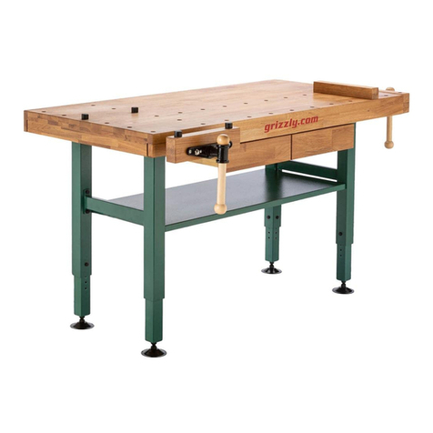
Work Bench with an All-Wood Top
Parts List "A"
Item Description Req'd.
1 Bench Top 1
2 Stringer 1
3 Leg Attachment Channel 2
4 Leg Weldment 2
5 Adjustable Foot 4
6 .312 (5/16) - 18 x .500 (1/2) Phillips T.H.M.S. 40
7 .312 (5/16) - 18 Keps Nut 32
8 .312 (5/16) - 18 Weldnut 8
Basic Work Bench
1
2
3
4
5
Parts List "B"
Item Description Req'd.
1 Maple Wood Top 1
2 Multi-Duty Wood Top 1
3 Stringer 1
4 Leg Weldment 2
5 Adjustable Foot 4
6 .312 (5/16) - 18 x .500 (1/2) Phillips T.H.M.S. 24
7 .312 (5/16) - 18 Keps Nut 16
8 .312 (5/16) - 18 Weldnut 8
3
4
5
12
1. Lay bench top (Item 1) upside down
on a at surface.
2. Insert leg attachment channel (Item
3) into bench top with the open area
of channel facing upward. Position
attachment channel so that the
holes in the end anges are in line
with the oval and rst hole in the
front and back anges of the bench
top. Fasten channel to bench top
with (4) screws and nuts (Items 6
& 7) as provided in the 00293-00
hardware pack. See Figure 1. Repeat
procedure at the other end.
3. Stand leg weldment (Item 4) in
place. (Leg fits inside attachment
channel). Position leg so that holes
in the sides of the leg weldment are
in line with the holes in the sides of
the attachment channel. Loosely
fasten leg and channel together with
(4) screws and nuts (Items 6 & 7) as
provided in 00293-00. See Figure 2.
Repeat procedure at the other end.
4. The stringer (Item 2) is to be attached
so the legs along the back edges of
bench. (BORROUGHS is stamped on
the front edge of Bench). Position
stringer so that the holes in the end
of the stringer are in line with the
holes in the leg. Fasten stringer to leg
with (4) screws and weldnuts (Items
6 & 8) as provided in 00664-00. See
Figure 3. Repeat procedure at the
other end. Tighten screws holding
leg weldments and attachment
channels together.
5. Insert adjustable foot (Item 5) into
leg so that the holes in the sides
of the foot are aligned with the
holes in the sides of the leg. At the
desired height, fasten foot to leg
with (4) screws and nuts (Items 6 &
7) as provided. See Figure 4. Repeat
procedure for the other legs.
5
FIGURE 4
2
FIGURE 3
4
5
FIGURE 7
21
3
8
11-
1. The stringer (Item 3) is to be attached
to the leg weldment (Item 4). Posi-
tion the stringer so that the holes
in the end of the stringer are in line
with the holes in the legs; located
approximately 11-5/8" down from
the top of the leg weldment. Fasten
the stringer to the leg with (4) screws
and weldnuts (Items 6 & 8) as provid-
ed. See Figure 5. Repeat procedure
at the other end.
2. Lay bench top (Item 1 or 2) upside
down on a at surface.
3. Place the leg weldment and stringer
assembly upside down on the bench
top. The stringer should be placed
toward the back edge of the bench
top. Position the leg weldment and
stringer assembly so it is centered
on the bench top and the legs are
parallel to the ends of the bench.
Use the leg weldments as templates
and drill (8) 1/4" pilot holes x 1" deep
for the lag screws at each end of the
bench top. Fasten the leg weldment
and stringer assembly to the bench
top with (8) .312 (5/16") x 1" lag
screws. See Figure 6. Lag screws are
not furnished by manufacturer.
4. Insert adjustable foot (item 5) into
leg so that the holes in the sides
of the foot are aligned with the
holes in the sides of the leg. At the
desired height, fasten foot to leg
with (4) screws and nuts (Items 6 &
7) as provided. See Figure 7. Repeat
procedure for the other three legs.
This completes assembly of the Work
Bench with an All-Wood Top. Put bench
in upright position.
~
FIGURE 1
FIGURE 2
FIGURE 6
FIGURE 5
Tools Required: 1. Phillips Screwdriver
2. 1/2" Open End or Box Type Wrench
Tools Required: 1. Drill with 1/4" Drill Bit
2. Phillips Screwdriver
3. 1/2" Open End or Box Type Wrench
4
6
67
67


