© 2009 Bosch Security Systems, Inc.
130 Perinton Parkway, Fairport, New York, USA 14450-9199
(800) 289-0096
06/09
DS924iPET Installation Instructions
P/N: F01U070392-04 Page 2
4.2 Attaching the Enclosure
• AttachthePIRbasetothemounting plate andtightenthemountingplate
locking screw.
• Replacethecover,engagingthe topfirst then securingthe bottomlatch.
• Foradded security,thecover maybe lockedtothe baselatch usingthe
smallscrew provided. Thescrew holein thebottomof thecover must
beknocked outprior toreplacing the cover.
5.0 Programming
General Guidelines
• PuttheControlPanelinprogrammode.
• Trip thesensor’stamperswitch byremoving its cover.
• Restorethe tamper byreplacing thesensor’scover.
Refertothe appropriateControl Panelinstallation manualfor specific
instructionsonprogramming thisdevice.
6.0 Walk Testing
6.1 Setup
Loosen the vertical adjust screw and set the vertical adjustment to -4°.
-4°
I
TEST
S
H
VERTICALADJUST
SCREW
0
4
8
0
4
8
Figure 5
6.2 Sensitivity Selection
• Locatethe sensitivitypins. Move theshorting jumperto theappropriate
pairof pins.
• Iftheshortingjumperisnotusedorplacedincorrectly,thesensordefaults
toIntermediatesensitivity.
Standard sensitivity is required for Pet Applications. This
settingisthe mosttolerantofenvironmental extremes.
Intermediate sensitivityshould beused forany locationwhere an
intruder is expected to cover only a small portion of the protected
area.This settingtolerates normal environments.Do not use this
setting for Pet Applications.
High sensitivity should only be used in quiet environments where
thermaland illuminationtransients arenotanticipated. Thissetting
has the fastest response to intruder signals. Do not use this
setting for Pet Applications.
6.3 Pattern Testing
Pressing the Walk Test Switch will start a 90 second Walk Test Mode.
During this Test Mode, any activity in the sensor’s coverage pattern will
causeatransmitted alarm andLED activation.Each alarmwill also extend
theTest Modeforan additional90seconds.
WalkTestingshouldbe doneacrossthe coveragepattern. Theedgeofthe
coverage pattern is determined by the first flash of the LED. This may
changeslightly dependingupon thesensitivitysetting. WalkTest theunit
frombothdirections todeterminethepattern boundaries.
Note: Excessive use of the Walk Test Mode may reduce battery
life. Use only for initial setup and maintenance testing.
Thedetection patternmay beshifted±10 degreeshorizontally byrotating
thelens leftorright totheappropriate marksonthe lensframe.
6.4 Final Testing
Turnon allheatingand airconditioningsources whichwould normally be
activeduringtheprotectionperiod.Standawayfromthesensorandoutside
thecoverage patternand watchfor alarms.
Aftersetup andtestsare completed,and therehas been noactivity in the
sensor’s coverage pattern for approximately 90 seconds, the LED will
flashto indicate thattheWalkTest modeisending.
Note: When the Walk Test Mode has ended, an alarm can be
transmitted only after three (3) minutes have passed since
the previous alarm. This 3 minute lockout time reduces
unnecessary RF transmissions in high traffic areas thereby
extending battery life.
6.5 Maintenance
Atleast once ayear,the rangeand coverageshould beverifiedfor proper
operation.To assuredaily operation,the end usershould be instructedto
walkthrough thefarend ofthecoverage patternto verifyan alarmoutput
priorto arming thesystem.
6.6 Battery Installation
The sensor is normally shipped with its battery installed. If battery
replacementis necessaryobserve properpolarity wheninstalling anew
batteryorthesensor maybe damaged. When thebattery is replaced,wait
at least 5 minutes after installing battery before activating the Walk Test
Mode.
7.0 RFTesting
TheactualRFtransmitterrange can bedeterminedby performing aDealer
Sensor Test as follows:
• Remove the sensor’s cover and press the Walk Test Switch. Refer to
Figure3 forthe switchlocation.
• Replacethe sensor’scover.
• Usingthe appropriatetouchpadfor theControlPanel, entertheDealer
SensorTest Code.
• Moveacrossthedetectionpatternuntilthesensor’sLEDturns on. STOP
yourmotion.
• Note the number of siren beeps indicating how many RF packets the
controlpanel receivedfrom thesensor.You shouldhear 7-8beeps. If
you hear 6 or fewer beeps, relocate the sensor and retest.
8.0 FCCNotice
ThisdevicecomplieswithPart 15 oftheFCC Rules. Operationissubject to
thefollowing twoconditions:
1. Thisdevice maynotcause harmfulinterference.
2. Thisdevice mustaccept anyinterference,including interferencethat
maycause undesired operation.
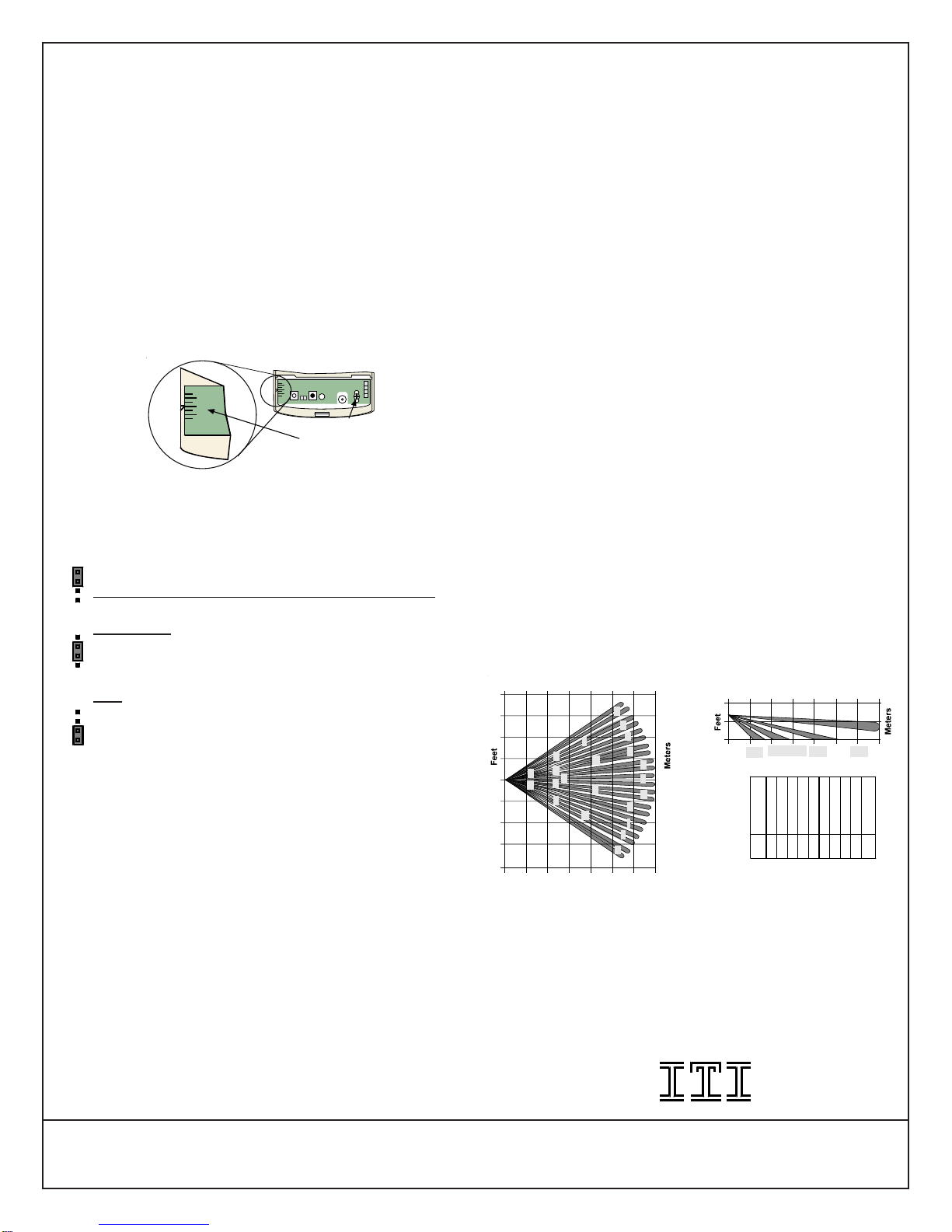
9.0 Coverage Patterns
DS924iPET Lens
ABCDEFGHIJK
PL MQ RN OTV SU
A-K
L-O
P-S & V
T-U 0
0035
11 3
10 Meters
Feet
0
6.5
6.5
0
ABC
DE
F
G
H
I
J
K
M
L
N
P
O
RV
U
T
S
Q
0
20
20 350Feet
11
0Meters
Figure 6
Changes or modifications not expressly approved by Interactive
Technologies, Inc.can voidthe user’s authority tooperatethe equipment.
®Interactive Technologies, Inc.
2266 North Second Street
North Saint Paul, MN 55109
1-800-777-1415
S
I
H
S
I
H
S
I
H


