manuals.online logo
Brands
  1. Home
  2. •
  3. Brands
  4. •
  5. Bosch
  6. •
  7. Accessories
  8. •
  9. Bosch ISC-SK10 User manual

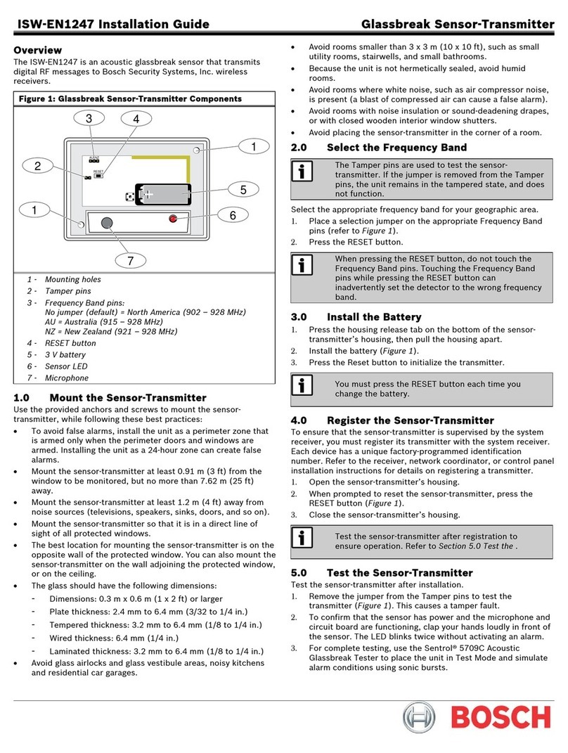
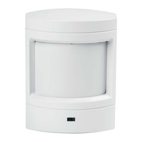
Bosch ISC-SK10 User manual

Table 2.1:
Maximum detection range
NOTICE!
Manual mode is active for 20 minutes
after power up.
NOTICE!
Cycle the sensor power after
changing switch settings.
NOTICE!
Do not use double-sided tape or
RTV which reduces vibration.
5 | Adjust potentiometer
Fine tune the sensitivity level by turning
the potentiometer clockwise to increase
sensitivity or counter-clockwise to decrease
sensitivity. During Self-learning mode, adjust
the potentiometer until the sensor LED turns
off, indicating that the sensor is correctly
configured.
Figure 5.1: Sensitivity potentiometer
– +
4 | Switch settings
The switch settings change sensor
configuration or sensitivity.
Figure 4.1: Switches
Switches 1 and 2 - sensitivity level setting.
Refer to sections 6 and 7 for configuring
these switch settings during installation.
Switch
Sensitivity Level
1 2
OFF OFF Low (default - least
sensitive)
OFF ON Low-medium
ON OFF High-medium
ON ON High (most sensitive)
4.2 | Set pulse count
Switch 4 Drill/saw detection
ON Disabled
OFF Enabled (default)
Switch 4 - drilling or sawing detection
setting.
4.5 | Set installation mode
Switch 6 - Manual or Self-learning mode
setting.
Switch 6 Installation mode
ON Self-learning mode
OFF Manual mode (default)
LED Condition
Green flash Vibration, movement,
contact or attack attempt
or during configuration.
Red on 2 seconds Alarm
Red on steady Sensor fault, sensor
position changed from
original installation.
Switch 5 LED function
ON Enabled (default)
OFF Disabled
Switch 3 Pulse count
ON 4 pulses
OFF 1 pulse (default)
4.3 | Set drill/saw detection
Switch 3 - pulse count setting. The sensor
generates an alarm when noise occurs
within the pulse count. When set to ON
the alarm triggers on 4 pulses within 40
seconds (15 seconds - 10 seconds - 15
seconds). When set to OFF, the alarm
triggers on the first pulse.
4.4 | Set LED
Switch 5 - LED setting. Do not disable this
setting during installation.
3 | Installation
Mounting the base:
1. Identify mounting location and surface.
2. Remove or drill through the mounting
holes in the base.
3. Insert the screws into the mounting
holes or use glue to secure the base to
the surface.
Figure 3.1: Unlocking and opening cover
1. Insert a slotted screwdriver into the
rotary lock on the front of the sensor
and turn counter-clockwise to the open
position (unlocked).
2. Pull apart the sensor from the top to
remove the cover from the base.
Figure 3.2: Screw locations
3.1 | Wiring
1. Insert the wire through the grommet
(removable). Refer to Figure 3.3.
2. Attach wire to the appropriate terminals.
Tamper and Alarm Contact normally-
closed (NC), Power 12VDC. Refer to Figure
3.4.
Figure 3.3: Wiring
Figure 3.4: Terminal
– Install the ISC-SK10 indoors and mount
on a variety of flat surfaces.
– Use the included screws or an adhesive
glue to secure the unit to the surface.
2 | Installation considerations
4.1 | Set sensitivity level
Surface Radius (m) Radius (ft)
Concrete 1.5 5
Brick wall 2.5 8
Steel 3 10
Wood 3.5 11.5
Glass 3.5 11.5
The ISC-SK10 is an advanced shock sensor
designed to monitor and detect mechanical
attacks.
Callout ― Description
1 ― LED
2 ― Potentiometer (sensitivity adjustment)
3 ― Cover tamper
4 ― Terminal block
5 ― Switches
Figure 1.1: ISC-SK-10 overview
32
5
14
1 | Overview
© 2016 Bosch Security Systems, Inc. F.01U.306.533 | 02 | 2016.04
en Installation Guide
Bosch Security Systems, Inc.
130 Perinton Parkway
Fairport, NY 14450
USA
www.boschsecurity.com
Copyright
This document is the intellectual property of Bosch
Security Systems, Inc. and is protected by copyright.
All rights reserved.
Trademarks
All hardware and software product names used in
this document are likely to be registered trademarks
and must be treated accordingly.
Bosch Security Systems, Inc. product
manufacturing dates
Use the serial number located on the product
label and refer to the Bosch Security Systems, Inc.
website at
http://www.boschsecurity.com/datecodes/.
Shock Sensor
ISC-SK10
Perform the following to set the sensitivity
manually when installing the sensor.
10 |
Certifications
Region Agency Certification
Europe CE EN 50130-4:2011
EN61000-6-3:2007/
A1:2011
EN60950-1:2006
9 | Specifications
Dimensions 100 mm x 30 mm x 20 mm
(3.93 in x 1.18 in x 0.78 in)
Voltage
(operating)
9-15 VDC, 12 V nominal
Current draw 8.5 mA (Standby), 12 mA
(Alarm)
Alarm output NC solid state relay, 100
mA@30 VDC
Tamper switch NC 50 mA@30 VDC
Operating
temperature
-10°C to +55°C (+14°F to
+131°F )
Relative humidity 0% to 95% non-condensing
Ingress
protection
IP43
Detection
method
Triaxial acceleration sensor
8 | Close the cover
1. Align the bottom of the cover to the
bottom of the base and attach the cover.
2. Insert a slotted screwdriver into the
rotary lock on the front of the sensor
and turn clockwise to the close position
(locked). Refer to Figure 8.1.
Figure 8.1: Closing the cover
7 | Manual mode
1. Power down the sensor and set
Switch 6 to OFF. Switches 1, 2, 3,
4, are OFF. Switch 5 is ON (default).
The potentiometer setting is medium
level. To set to medium level, turn the
potentiometer down (counter-clockwise)
as far as possible. Then, turn half way
up (clockwise) until the slot is pointed
up in the center position. Refer to Figure
7.1 below.
Figure 7.1: Medium potentiometer setting
NOTICE!
When the LED turns off, the
sensor is configured.
5. Turn the Potentiometer slowly based on the
LED response.
6. Repeat steps 4 and 5 until the desired
sensitivity is achieved.
7. Power up the sensor and wait for 2
seconds. The sensor is now configured.
2. Power up the sensor and wait for 2
seconds. During this time, do not
remove or disturb the sensor. The LED
flashes green once when ready.
3. Simulate noise within the detection
range of the sensor for 3 minutes. The
sensor records, and the LED flashes
green for each noise detected during the
3 minute duration.
4. When the LED flashes red, adjust the
sensitivity level (Switch 1 and Switch 2).
Refer to section 4.1 for sensitivity levels.
6 | Self-learning mode
Perform the following to use Self-
learning mode when installing the sensor
(recommended method).
1. Power down the sensor and set Switch
6 to ON (Self-learning mode). Switches
1, 2, 3, 4, are OFF. Switch 5 is ON
(default). The potentiometer setting
does not matter.
2. Power up the sensor and wait for 2
seconds. During this time, do not
remove or disturb the sensor. The LED
flashes green once when ready.
3. Simulate noise within the detection
range of the sensor for 3 minutes. The
sensor records, and the LED flashes
green when vibration is detected during
the 3 minute duration.
4. When finished sensing and recording,
the red LED flashes quickly. Set Switch
6 to OFF:
• If the LED turns off, then the settings
are correct, no adjustment is required.
• If the red LED turns on steady,
skip to step 5 below to adjust the
potentiometer.
• If the LED begins flashing in a pattern,
continue with step 4 to adjust the
DIP switches. Set the sensitivity level
(Switch 1 and Switch 2). Refer to Table
6.1 below for switch settings.
5. After setting the switches:
• if the LED is off, no adjustment is
needed.
• if the red LED is on, turn the
potentiometer slowly until it turns
off.
6. Cycle the power of the sensor and
wait for 2 seconds. The sensor is now
configured.
Red LED flashing Switch 1 Switch 2
4 x ON ON
3 x ON OFF
2 x OFF ON
1 x OFF OFF
Table 6.1: LED flashing states
Other Bosch Accessories manuals

Bosch SCD 110 User manual

Bosch

Bosch SCD 110 User manual

Bosch Sense T User manual

Bosch

Bosch Sense T User manual

Bosch PFB3060 User manual

Bosch

Bosch PFB3060 User manual

Bosch Deepfield Connect Premium User manual

Bosch

Bosch Deepfield Connect Premium User manual

Bosch PLS User manual

Bosch

Bosch PLS User manual

Bosch RADION glass break User manual

Bosch

Bosch RADION glass break User manual

Bosch IVAS 0273600075 User manual

Bosch

Bosch IVAS 0273600075 User manual

Bosch MSE-LZ User manual

Bosch

Bosch MSE-LZ User manual

Bosch SCD 110 User manual

Bosch

Bosch SCD 110 User manual

Bosch KTR SERIES User manual

Bosch

Bosch KTR SERIES User manual

Bosch rexroth APAS CDE V01.00.00 User manual

Bosch

Bosch rexroth APAS CDE V01.00.00 User manual

Bosch Rexroth VarioFlow plus User manual

Bosch

Bosch Rexroth VarioFlow plus User manual

Bosch Rexroth BS 1/T User manual

Bosch

Bosch Rexroth BS 1/T User manual

Bosch FR5CUEC User manual

Bosch

Bosch FR5CUEC User manual

Bosch CANbus LCD User manual

Bosch

Bosch CANbus LCD User manual

Bosch rexroth PSM User manual

Bosch

Bosch rexroth PSM User manual

Bosch PRS-1AIP1 User manual

Bosch

Bosch PRS-1AIP1 User manual

Bosch SCD 110 User manual

Bosch

Bosch SCD 110 User manual

Bosch PSJ120S Assembly instructions

Bosch

Bosch PSJ120S Assembly instructions

Bosch ManDown Sensor User manual

Bosch

Bosch ManDown Sensor User manual

Bosch DS924i User manual

Bosch

Bosch DS924i User manual

Bosch CleverMixx MSM1 IN Series User manual

Bosch

Bosch CleverMixx MSM1 IN Series User manual

Bosch BGS6235GB User manual

Bosch

Bosch BGS6235GB User manual

Bosch SCD 110 User manual

Bosch

Bosch SCD 110 User manual

Popular Accessories manuals by other brands

NA-DE 10820 instruction manual

NA-DE

NA-DE 10820 instruction manual

Loadstar Sensors DI-1000UHS-10K user guide

Loadstar Sensors

Loadstar Sensors DI-1000UHS-10K user guide

Work Sharp WSKTS2-I user guide

Work Sharp

Work Sharp WSKTS2-I user guide

Empire Comfort Systems PVSRT1-1 installation instructions

Empire Comfort Systems

Empire Comfort Systems PVSRT1-1 installation instructions

SICK MLS operating instructions

SICK

SICK MLS operating instructions

Yost Labs 3-Space Bluetooth user manual

Yost Labs

Yost Labs 3-Space Bluetooth user manual

HSS Hire 56772 Operating & safety guide

HSS Hire

HSS Hire 56772 Operating & safety guide

TruGolf TruBalance Mobile Getting started

TruGolf

TruGolf TruBalance Mobile Getting started

Fiamma F65s series Installation and use instructions

Fiamma

Fiamma F65s series Installation and use instructions

Taurus Comfort Therm UB 81 instructions

Taurus

Taurus Comfort Therm UB 81 instructions

Focusrite rednet am2 user guide

Focusrite

Focusrite rednet am2 user guide

Aron QBox user manual

Aron

Aron QBox user manual

Electrovaya PowerPad 160 Safety and instruction manual

Electrovaya

Electrovaya PowerPad 160 Safety and instruction manual

Miele SEB 234 -  2 operating instructions

Miele

Miele SEB 234 - 2 operating instructions

ProtoStar Model 2 Installation & use guide

ProtoStar

ProtoStar Model 2 Installation & use guide

Nolii Super Stack manual

Nolii

Nolii Super Stack manual

Livox Tele-15 quick start guide

Livox

Livox Tele-15 quick start guide

Johnson Controls WRZ-TTB0000-5 installation guide

Johnson Controls

Johnson Controls WRZ-TTB0000-5 installation guide

manuals.online logo
manuals.online logoBrands
  • About & Mission
  • Contact us
  • Privacy Policy
  • Terms and Conditions

Copyright 2025 Manuals.Online. All Rights Reserved.