Bosch PIVOT SHUTTLE AM Quick start guide

www.pivotcycles.com info@pivotcycles.com 1.877.857.4868 1
Original Operational Instructions
SHUTTLE AM

PIVOT SHUTTLE AM
Original Operational Instructions
This manual is intended to provide you with the information
needed to get you on the trail, walk you through the steps
necessary to set up all the components, and become familiar
with the Bosch E-bike System. This document contains some
helpful diagrams and reference material to make sure you have
everything necessary to maintain your Shuttle AM and enjoy it
to the fullest.

TABLE OF CONTENTS PAGE
1. Quick Start Guide 1
- Basic Suspension/Tire Set-up 1
- Adjusting Saddle Height 1
- Charging the Battery 1
- Powering the System ON and OFF 1
- Mini Remote and System Controller Function 2
- Adjusting Levels of Assistance 2
2. Bike Set-up 3
- Setting Proper Sag 3
- Setting Compression Damping on the Fox Float X 3
- Using the Climb Switch on the Fox Float X 3
- Setting Rebound Damping on the Fox Float X 4
- Setting Air Pressure on Fox 36 and 38 Forks 4
- Setting Compression Damping on Fox 36 and 38 Forks 5
- Setting Rebound Damping on Fox 36 and 38 Forks 5
- Recommended Tire Pressure 5
3. System Operation 6
- Battery Charge Indicator 6
- Establishing a Smart Phone Connection 6
- Connecting the Mini Remote to the System Controller 6
- Rim Magnet Speed Sensor 6
4. System Information 7
- Riding Mode Customization 7
- Display Options 7
- eBike Lock 7
- Connect Module 7
- System Updates 7
- Error Messages 7
5. Schematics 8
- Bosch Drive System Schematic 8
- Small Parts Schematic 9
- Small Parts Table 10
- Wiring Diagrams 11
7. Additional Information 12
- Bicycle Safety 12
- Battery Safety 12
- Sources 13
- Notes 14

QUICK START GUIDE
Suspension/Tire Set-up
This "Quick Start Guide" provides the essential information to set up your bike.
COMPONENT QUICK START SETTING
Shock Air Pressure
(by Body Weight)
! Always Check Sag
see page 3 !
Body Weight in [kg] to [bar] 0.15 × Body Weight [kg] + 2 [bar]
Body Weight in [kg] to [psi] 2.2 × Body Weight [kg] + 30 [psi]
Body Weight in [lbs] to [bar] 0.07 × Body Weight [lbs] + 2 [bar]
Body Weight in [lbs] to [psi] Body Weight [lbs] + 30 [psi]
Shock Compression Damping 8 clicks in from OPEN*
Shock Rebound Damping 6 clicks in from OPEN
Fork Air Pressure 80 [psi] / 5.52 [bar]
Fork Compression Damping HSC: 2 clicks in from OPEN*; LSC: 5 clicks in from OPEN
Fork Rebound Damping HSR: 3 clicks in from OPEN*; LSR: 7 clicks in from OPEN
Front Tire Pressure 23 [psi] / 1.58 [bar]
Rear Tire Pressure 28 [psi] / 1.93 [bar]
* These Adjustments are not available on all builds.
Adjusting Saddle Height
1. Use a 2mm hex wrench, loosen the drive side cable port cap securing the dropper
post housing. (fig. 1)
2. Using a 4mm hex wrench, loosen the seat post clamp bolt and raise/lower the
saddle to the preferred height. (fig. 2)
3. Using a 4mm hex wrench, tighten the seat post clamp bolt to 5 Nm.
4. Tighten the cable port cap screw with a 2mm hex wrench to secure the dropper
post housing.
Charging the Battery
NOTE: The battery does not come fully charged and must be charged com-
pletely before the first use.
1. Locate the rubber charging port cover on the non-drive side of the frame. (fig.3)
2. Pull back the sealing cover to access the charging terminal.
3. Insert the charging cable into the charging terminal, ensuring the cable and
terminal are properly aligned. (fig. 4)
4. The system controller will illuminate and display the charging status.
5. When done charging, remove the cable from the terminal and close the sealing
cover.
6. The LED bars on the System Controller indicate the state of the battery's charge.
Powering the System ON and OFF
1. The power button is located in the system controller on the top tube. (fig. 5)
2. Power the system on or off with a quick press and release on the power symbol
near the top of the controller. The System Controller will power up and power
down with an animation of the five LED bars.
3. If the bike has not moved for 10 minutes, the power will shut off automatically.
*The battery is fixed in the frame and should only be removed by an authorized
dealer.
3
5
1
2mm
2
4mm
4

QUICK START GUIDE
Mini Remote and System Controller Function
(1) Mini Remote operating unit
(2) System Controller
(3) LED indicator lamp
(4) Button for increasing support level +/ bike lights
(5) Select Button
(6) Button for decreasing support level -/walk assistance
(7) Rubber insert/battery holder
(8) Holder
(9) Fastening screw for holder
(10) Assistance level LED
(11) ABS LED (optional)/ ambient light sensor
(12) On/off button
(13) LED's for battery charge indicator
(14) Mode Button
Adjusting the Level of Assistance
• The assist level can be selected with the Mini Remote (1) or with the System Controller (2).
• Mini Remote: Briefly press (< 1 s) the + (4) button to increase assistance. Briefly press (< 1 s) the - (6)
button to decrease assistance.
• System Controller: Briefly press (< 1 s) the mode button (14) to increase assistance.
• Press the mode button (14) for longer than 1 s to decrease the assistance.
• The assistance level can be changed at any time, even while cycling, and is displayed in color on the
Assistance level LED (10). See the table below for assist modes, LED color, and description.
• The Shuttle AM also features walk assist. To start walk assistance, press the (6) button for < 1 s and
keep it pressed. The battery charge indicator (13) goes out and a white moving light in the direction
of travel shows that it is ready. Releasing the (6) button pauses walk mode.
LED COLOR ASSIST DESCRIPTION
LED OFF Motor support is switched off. The bike can be pedaled as a normal bike
GREEN Effective support with maximum efficiency, for maximum range
BLUE Steady support, long range for touring
PURPLE Optimal support whatever the terrain, improved dynamics and top performance
RED Maximum support even at a high cadence, for sport cycling
FLASHING SEQUENCE Walk assist. The battery charge indicator (13) LEDs turn off then flash in the direction of travel.
(1)
(2)
(3)
(4)
(5)
(6)
(10)
(7)
(8) (9)
(11)
(12)
(13)
(14)

BIKE SET-UP
FLOAT X
Setting Compression Damping on the Fox Float X
• Some Factory Series Float X features a blue low speed compression
adjustment knob, which can be used to fine tune the open mode of the
compression damping. This knob offers 10 additional fine tune adjustment
settings to the open mode.
• Turning the knob clockwise will increase low speed compression damping.
Turning the knob counter-clockwise will decrease low speed compression
damping. You can experiment with all of these options to find the setting that
provides the best compression support and plushest feel for your weight and
riding style.
• For a rider close to 100lbs, we recommend having the compression fully open, by
having the knob turned fully counter-clockwise. For riders 200lbs we like to start
at 3 clicks in from full closed as a good baseline setting. If the rider's weight is less
than 200lbs, open up compression damping 1 click counter-clockwise for every
10lbs. less. For every 10lbs over 200lbs we recommend increasing compression
damping by 1 click clockwise.
Using the Climb Switch on the Fox Float X
Some Float X shocks feature a two position lever allows for on-the-fly adjustment
between fully open and firm for climbing, As with other shocks, the firm setting is
best suited for long fire road climbs and smooth XC courses.
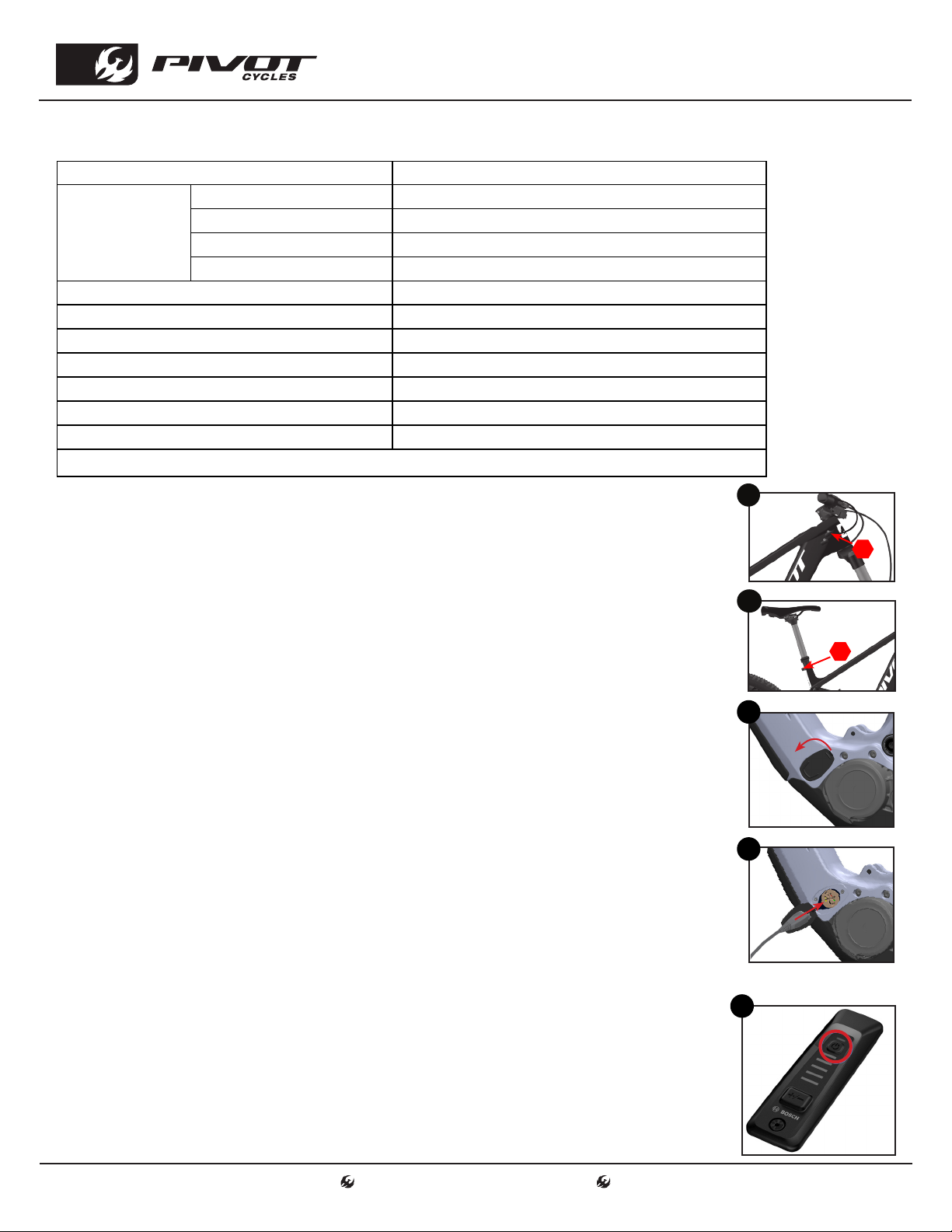
Setting Proper Sag
1. Always set sag with the blue climb switch lever to the
open position. (fig. 1)
2. If your shock has additional compression and rebound
adjustments ensure they are adjusted to be fully open,
compression to the softest setting, and rebound to its
fastest setting. Do this by rotating them fully counter-
clockwise.
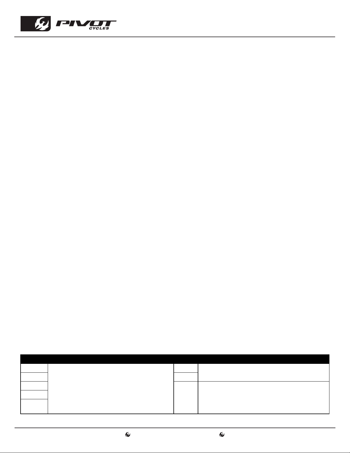
3. If it is not installed already, attach the sag indicator to
the bottom of the shock body using the provided zip-tie
and carefully cut the excess.(fig. 2)
4. Find a level surface and something to steady yourself
while mounted on the bike so you can be on the pedals
in a seated position. It may be easier to have a partner
hold your bike steady from the front, by holding the
handlebars while you are in your riding position.
5. While standing on the pedals, sit down hard into the
saddle to cycle the suspension well into the stroke.
This will ensure the bike comes to rest at the natural
sag setting with the rider in the saddle.
6. While in the saddle and not moving, slide the O-ring up
into position against the air can. (fig. 3)
7. Once the O-ring is set in place, slowly step off the bike
so as not to move the O-ring.
8. Make adjustments to the sag by removing or adding
air so that steps 4-7 result in the O-ring lining up with
the red line on the sag indicator. (fig. 4) When adjusting
air pressure in the shock, cycle the shock before re-
checking sag, so the large Evol negative air chamber equalizes pressure with the main chamber each time
air is added or removed. You can do this by pushing down on the saddle several times to compress the
shock past the sag point.
WARNING: Make sure the sag
indicator does not contact the
frame or linkage through the
suspension cycle. Otherwise,
the indicator may break while
riding.
CLIMB SWITCH OPEN
2 POSITION
LEVER
23
4
1
OPEN COMPRESSION
DAMPING
LOW SPEED
COMPRESSION KNOB

BIKE SET-UP
AIR PRESSURE SUGGESTED REBOUND
SETTING FLOAT X
[bar] [psi]
< 8.3 <120 1 (9)
8.3 - 9.7 120-140 2 (8)
9.7 - 11 140-160 3 (7)
11 - 12.4 160-180 4 (6)
12.4 - 13.8 180-200 5 (5)
13.8 - 15.2 200-220 6 (4)
15.2 - 16.5 220-240 7 (3)
16.5 - 17.9 240-260 8 (2)
17.9 - 19.3 260-280 9 (1)
19.3 - 20.7 280-300 CLOSED
Clicks from OPEN (Clicks from CLOSED)
Setting Air Pressure on the Fox 36 Forks
• Fox recommends setting sag between 15% and 20% of the total fork travel. The Shuttle AM comes
with a 160mm fork, so the proper sag measurement is 24.0 - 32.0mm.
• The air pressure in the Fox 36 forks should not exceed 8.3 [bar] (120 [psi]).
• To achieve the proper sag, reference the chart below for an initial starting point.
• Just like with the shock sag the fork needs to be equalized when the pressure is changed. Press
down on the fork a few times after making a pressure change to get an accurate measurement.
RIDER WEIGHT FOX 36
AIR PRESSURE
[kg] [lbs]
55 - 59 120 - 130 58 [psi] / 4.0 [bar]
59 - 64 130 - 140 64 [psi] / 4.4 [bar]
64 - 68 140 - 150 68 [psi] / 4.7 [bar]
68 - 73 150 - 160 72 [psi] / 5.0 [bar]
73 - 77 160 - 170 76 [psi] / 5.2 [bar]
77 - 82 170 - 180 80 [psi] / 5.5 [bar]
82 - 86 180 - 190 84 [psi] / 5.8 [bar]
86 - 91 190 - 200 89 [psi] / 6.1 [bar]
91 - 95 200 - 210 93 [psi] / 6.4 [bar]
95 - 100 210 - 220 97 [psi] / 6.7 [bar]
100 - 105 220 - 230 102 [psi] / 7.0 [bar]
105 - 109 230 - 240 106 [psi] / 7.3 [bar]
109 - 114 240 - 250 110 [psi] / 7.6 [bar]
Setting Rebound Damping on the Fox Float X
• Rebound is set from the most open (fully counter-clockwise) position.
• The rebound setting is determined by the air pressure in the shock.
• Refer to the table below for the suggested rebound setting. The number
in the chart refers to how many clicks in (clockwise) from the open
setting the rebound should be set. Fox sets rebound from the closed
position, so that has been provided in the table in parentheses.
FLOAT X REBOUND KNOB

BIKE SET-UP
Setting Compression Damping on the Fox 36 Grip 2 Forks
• To set compression, start from the open (or fastest) position by turning the black
(LSC) dial & blue (HSC) dial counterclockwise until they stop clicking.
• A good starting point for most riders is to turn the black (LSC) dial clockwise 5 clicks
& turn the blue (HSC) dial clockwise 2 clicks.
• The recommended starting points may need to be adjusted based on rider weight.
Lighter riders may prefer less compression damping (fewer clicks from open).
Setting Rebound Damping on the Fox 36 Forks
• Remove the protective cover over the rebound knobs on the lower fork leg.
• To set rebound, start from the open (or fastest) position by turning the red rebound
dial(s) on the bottom of the right fork leg counterclockwise until it stops clicking. On
the Fox 38 Grip 2 there are two dials. One for high speed and one for low speed.
• Refer to the chart below for the recommended settings when setting rebound. Fox
clicks are in parentheses.
RIDER
WEIGHT
FOX 36 SUGGESTED REBOUND
LSR / HSR *HSR not available on all builds
120-130 [lbs] 3 / Open (12 / 10)
130-140 [lbs] 4 / Open (11 / 10)
140-150 [lbs] 5 / 1 (10 / 9)
150-160 [lbs] 6 / 2 (9 / 8)
160-170 [lbs] 7 / 3 (8 / 7)
170-180 [lbs] 8 / 4 (7 / 6)
180-190 [lbs] 8 / 4 (7 / 6)
190-200 [lbs] 9 / 5 (6 / 5)
200-210 [lbs] 9 / 5 (6 / 5)
210-220 [lbs] 10 / 6 (5 / 4)
220-230 [lbs] 11 / 7 (4 / 3)
230-240 [lbs] 11 / 7 (4 / 3)
240-250 [lbs] 12 / 8 (3 / 2)
Clicks from OPEN (Clicks from CLOSED)
Recommended Tire Pressure
• Tire pressure is an important factor on having the bike ride properly. If the tire pressure is too high, the tire
will not conform to ground, reducing traction. If the tire pressure is too low, the tire could pinch flat.
• It is important to have an accurate pressure gauge when setting tire pressure; preferably a digital gauge
with a 0.03 [bar] (0.5 [psi]) accuracy.
• The recommended tire pressure will vary slightly based on rider weight, riding style, and terrain.
• Some riders may find it helpful to start a ride at a slightly higher pressure than recommended and let out a
little air throughout the course of the ride until you find your ideal riding tire pressure.
RECOMMENDED TIRE PRESSURE
FRONT REAR
1.58 [bar] / 23 [psi] 1.93 [bar] / 28 [psi]
Setting Compression Damping on the Fox 36 Grip Forks
• We always start with the lever in the full open position. Most riders will not need to
make any changes from this position.
• If you do need more compression support, the lever will provide a low speed
compression adjustment until the lever is turned halfway.
• Fully closed provides a nearly locked out feel for climbing.
GRIP Compression
Knob
GRIP2 Compression
Knob
Protective Cover
LSR
HSR

SYSTEM OPERATION
Battery Charge Indicator
• The top LED on the System Controller flashes to indicate that the battery is being charged
when the charger is connected to the charging port.
• The state of charge of the battery can also be checked on the LEDs of the battery itself.
• On the display, each ice-blue bar represents 20% capacity and each white bar represents
10% capacity. The top bar shows the maximum capacity. Example: Four ice-blue bars and
one white bar are displayed. The state of charge is between 81% and 90%.
• If the capacity is low, both the lower bars change color. When the bottom two LEDs are
orange there is 30-21%.
• If the bottom LED is the only one illuminated orange, the capacity is 20-11%.
• If the bottom LED is red, the capacity is 10% to reserve. And when flashing red it is between reserve and empty.
Establishing a Smartphone Connection
In order to use some of the eBike functions, a smartphone with the eBike Flow app is required.
Download the Bosch eBike Flow app to your smartphone from the app store and follow the
instructions on the app.
Connecting the Mini Remote to the System Controller
• The System Controller and Mini Remote operating units are connected via Bluetooth®. If the Mini
Remote operating unit has not already been connected to the System Controller proceed as follows:
• When connecting a Mini Remote, go to settings then click on manage bike settings, then click on
components, then click on add new device. Then follow app instructions.
Rim Magnet Speed Sensor
• The Shuttle AM features the Rim Magnet instead of a rotor
magnet and wired speed sensor. The drive unit itself detects
when the magnet is close to it and calculates the speed and
any other data required.
• The Rim Magnet must be installed on the wheel for the
motor to provide assist.
• Since the drive unit is sensitive to magnetic fields, avoid
other magnetic fields in the vicinity of the drive unit (e.g.
magnetic clipless pedals, magnetic cadence sensors, etc.) in
order to prevent disruption to the drive unit.
• If you get a flat tire on a ride you will need a tube with at
least a 32mm long valve stem to mount the rim magnet on.
eBike Flow App

SYSTEM INFORMATION
Riding Mode Customization
In the eBike Flow App you can adapt selected riding modes exactly to your needs: You can fine-tune rid-
ing modes so that they offer you more support or consume less power.
Error Messages
The control unit shows whether critical errors or less critical errors occur in the eBike system. The er-
ror messages generated by the eBike system can be read via the eBike Flow app or by your Pivot dealer
along with support for fix the error.
• The warning code will clear once the issue is resolved.
• If any issues persist after the suggestions below, contact your Pivot dealer.
• Less critical errors are shown by the assistance level LED flashing orange. Press the select button on
the Mini Remote or mode button on the System Controller to confirm the error. The assistance level
LED will once again continuously show the color of the set assistance level.
• Critical errors are shown by the assistance level LED and the battery charge indicator flashing red.
LESS CRITICAL ERRORS CRITICAL ERRORS
523005 The indicated error numbers show that there is inter-
ference with the speed sensor. See if you have lost the
magnet while riding. Make sure your rim magnet does
not have any magnetic interference in the vicinity of the
drive unit. (magnetic pedals, cadence sensors, etc.)
660001 Do not charge the battery and do not continue to use!
Please contact your Pivot dealer.
514001 660002
514002 890000 Acknowledge the error code. Restart the system.
If the problem persists: Acknowledge the error code.
Perform a software update. Restart the system
If the problem persists: Please contact your Pivot dealer.
514003
514006
Display Options
Bosch offers a few different display options you can integrate with your Shuttle AM. Bosch also offers
different mounts if you would like to use your smart phone as a display with the eBike Flow App.
eBike Lock
Using the eBike Flow App you can activate the eBike Lock feature for your Shuttle AM. The lock feature
allows you to disable the assist and your smart phone works like a key to unlock your bike. The settings
for this feature can be turned on, off, or adjusted in the settings of the eBike Flow App.
ConnectModule
The Shuttle AM is built to accomodate the ConnectModule. This unit can be added to your bike by your
dealer. The ConnectModule features an audible alarm if your bike is moved. It also will send you a mes-
sage alert if your bike is moved a lot. This unit also features GPS tracking so you will always know where
your bike is.
System Updates
Like most modern devices, system improvements and features are developed over time. You can keep
your Shuttle AM current with the lastest updates through the eBike Flow App. In the app you can install
the updates to your bike. You can also take your bike in to your local Pivot Dealer for them to install any
updates.

Bosch Drive System Schematic
LETTER PART DESCRIPTION PART NAME
A Mini Remote EB13.100.001
B System Controller EB13.100.000
C
PowerTube 750 Battery (US, CAN, JP, KOR)
PowerTube 750 Battery (EU28, CH, NO, AUS, NZ)
PowerTube 625 Battery (Ride Level Builds US, CAN, JP, KOR)
PowerTube 625 Battery (Ride Level Builds EU28, CH, NO, AUS, NZ)
EB12.100.00Z
EB12.100.00X
EB12.100.013
EB12.100.011
D Rim Magnet (Speed Sensor) EB11.200.015
E
Spider & Chainring (Ride Builds)
Spider & Chainring (Pro Builds)
Spider & Chainring (Team Builds)
ES-BSC-104-565-34T
ES-BSC-104-565/ 00.6218.034.003
F&G Drive Unit Lockring & O-Ring 1270.014.085/ 1270.016.119
H
Crank Arms (Ride Builds)
Crank Arms (Pro Builds)
Crank Arms (Team Builds)
EC-1ISIS-160A
EC-1ISIS-160A
EC-1ISIS-160CM
I
CX Performance Drive Unit
CX Performance Race Edition Drive Unit
EB11.100.000
EB11.100.00G
J Charging Socket & Cable EB12.120.048
K Charging Socket Cover EB12.120.01B
L
Battery Charger 4A110V/Cable (US)
Battery Charger 4A 230V/Cable(EU)
Battery Charger 4A 230V/Cable(AUS)
Battery Charger 4A 230V/Cable(UK)
EB12.110.000/ 1270.020.343
EB12.110.001/ 1270.020.330
EB12.110.001/ 1270.020.344
EB12.110.001/ 1270.020.331
SCHEMATICS
(C)
(D) (E) (F&G)
(A)
(B)
(H)
(J&K)
(L)
(I)

Small Parts Schematic
SCHEMATICS
ATTENTION:
Lower links are
marked with an arrow
on the non-drive side.
The link must be
oriented where the
arrow points to the
front triangle.

SCHEMATICS
Hardware
NUMBER PART NUMBER DESCRIPTION TORQUE *
3FP-CVR-SKIDPLT-SHTV6-V1-R1 Shuttle V6 Skid Plate
4FP-UDH-TA-12MM-BLK-V1-R1 Universal Rear Derailleur Hanger
5 - Universal Rear Derailleur Hanger Bolt 25 Nm (18 lb·ft)
6 - Universal Rear Derailleur Hanger Washer
7FP-LNK-UL-68MM-V1-R1 68mm Upper Link
8FP-LNK-LL-50MM-V3-R1 50mm Out-to-Out Lower Link V3
9FP-BRG-6902-LLUMAXECN 28mm 6902 Extended Max-E Bearing R
10 FP-BRG-6902-LLUMAX 28mm 6902 Standard Max Bearing R
11 FP-BRG-6900-LLUMAXE 22mm 6900 Ext'd Max-E Bearing R
12 FP-BLT-M8*45.7-BLK-V2 M8 Front Shock Bolt for 30.1mm Shock Spacing 13 Nm (10 lb·ft) G / L
13 FP-BLT-M14*20-BLK-V2-R2 M14x20 Link Bolt 35 Nm (27 lb·ft) L
14 FP-BLT-M10*16.5-BLK-V1 M10 Trunnion Mount Bolt 13 Nm (10 lb·ft) L
15 FP-BLT-M14*20-BLK-V3-R2 M14x20 Flip Chip Bolt 35 Nm (27 lb·ft) L
16 FP-NUT-FLIPCHIP-4.6MM-V1 4.6mm Flip Chip G
17 FP-WSH-SPC-15I*25O*3W M14x3mm Flip Chip Spacer G
18 FP-CLM-MECH-FRM-V1 Internal Routing Cable Clamp
19 FP-CVR-MECH-FRM-V2 Internal Routing Hole Cover
20 FP-CLM-DUAL-FRM-V1 Internal Routing Dual Clamp
21 FP-CLM-MECH-FRM-V2 Internal Routing Cable Clamp (Mirrored)
22 FP-CVR-MECH-FRM-V4 Internal Routing Cable Cap (Mirrored)
23 FP-SCW-FLT-M3*10-BLK CABLE PORT CLAMP SCREW BLACK
24 FP-CLM-ADEL-V1-R1 Cable Routing Adel Clamp
25 FP-SCW-BTN-M4*12-BLK-V1-R1 M4x12 Adel Clamp Mounting Bolt
26 FP-PLG-DI2-7*8*5 7x8mm Di2 Plug Ext'd
27 FP-BLT-BTN-M5*6-V1-R1 M5x6 DT Water Bottle Bolts 3 Nm (26 in·lb) L
28 PIVOT WB BOLTS V2 Top Tube Tool Bolts
29 FP-SCW-SCK-M8*18-R1-BLK M8X18 SOCKET HEAD SCREW BLACK 13 Nm (10 lb·ft) L
30 FP-WSH-8I*12O*1W-BLK M8 WASHER BLACK
31 FP-SCW-BTN-M6*14-BLK-V1-R1 M6x14 Front Bracket/Skid Plate Bolts 6 Nm (53 in·lb) L
32 FP-SCW-SCK-M6*16-BLK-V1-R1 M6x16 Rear Bracket Bolts 6 Nm (53 in·lb) L
33 FP-WSH-M6-BLK-V1-R1 M6 Washer Black
34 FP-MNT-FRNT-BATT-SLTV2-V1-R1 Front Battery Bracket
35 FP-MNT-REAR-BATT-SLTV2-V1-R1 Rear Battery Bracket
36 FP-BLT-SCK-M3*10-V1-R1 Battery Mounting Bolts 1 Nm (9 in·lb)
37 FP-BATT-PAD-60*70-V1-R1 Upper Battery Pad
38 FP-BATT-PAD-LWR-87.3MM-V1-R1 Lower Battery Pad
39 FP-PRO-SHTV6-DT-V1-R1 SHTLv6 Downtube Protector
40 FP-PRO-SHTV6-CS-V1-R1 SHTLv6 Chainstay Protector
41 FP-PRO-SHTV6-SS-V1-R1 SHTLv6 Seatstay Protector
42 FP-PRO-SHTV6-UR-V1-R1 SHTLv6 Upright Protector
43 FP-PRO-LL-50MM-V3-R1 Lower Link Protector
44 -Frame Size Sticker
Bike Care
*PRODUCT TYPE RECOMMENDED PRODUCT TORQUE *
GGrease Motorex Bike Grease 2000
LThread Locker** Loctite Thread Locker #243 (or equivalent)
G/L Grease (Bolt Shaft) Thread Locker (Bolt Threads) See Above 25 Nm (18 lb·ft)
AAnti-Seize Motorex Copper Paste
RRetaining Compound Loctite Retaining Compound #620 (or equivalent)
**Threadlocker should always be applied to the corresponding female threads for the bolt specified
Axles
NUMBER PART NUMBER DESCRIPTION TORQUE *
101 157MM THROUGH AXLE V5 157mm UDH Rear Axle 15 Nm (11 lb·ft) G
102

Shuttle AM Wiring Diagram
• The diagrams below will help illustrate how the wires are to be routed through the internal cable guides.
• The routing shown below will help minimize the likelihood of pinching a wire when removing and installing
the motor for maintenance purposes.
SCHEMATICS
System Controller Wire
Battery Wire
Charging Port Wire
Shift Housing
Brake Line
Dropper Post Housing
Frame Wiring Diagram
Side View of System Wiring Top View of System Wiring

ADDITIONAL INFORMATION
Bicycle Safety
This bike is not designed or equipped for use on public roads. Before it can be used on public roads it
must be fitted with the legally prescribed equipment. It is designed to be used off-road, but not for com-
petitions. The manufacturer and dealer accept no liability for damage resulting from any use beyond this
definition and/or failure to comply with the safety information and instructions in this user guide. This
applies particularly to, but not limited to, the use of this bike in competitions, overloading, and the failure
to properly rectify faults. Intended use also includes conformance with the specified operating, service,
and repair conditions in the user guide. Fluctuations in the consumption and power of the battery and a
reduction of capacity with increasing age are common and technically unavoidable, and as such, do not
constitute material defects.
Battery Safety
• Refer to the current Bosch battery manual from safety and care instructions before use.
• Batteries are subject to the dangerous goods regulations. Private users are permitted to transport
them on the road without further conditions. If transported by commercial third parties (e.g. by air
freight, logistics companies, or postal service) special conditions apply to packing and labeling. For
questions about transporting batteries, please contact your local Pivot dealer.
• Damaged batteries must not be charged, used, or transported. They can explode and cause serious
burns or fires. Gases can be released and irritate the airways. Ensure there is a supply of fresh air and
consult a doctor in the event of discomfort. Liquid can escape and cause skin irritation. Avoid contact
with this liquid, but in case of accidental contact, wash off with water. If the liquid gets into the eyes,
flush out with water and seek medical attention.
• Batteries must not be submerged in water. There is a risk of explosion. Do not attempt to extinguish a
burning battery with water, only the surrounding burning material. For burning batteries, use a Class
D Fire Extinguisher. If it is possible to take the battery safely outside, smother the fire with sand.
You do not need to worry that you are in danger when riding in the rain; the battery is protected from
moisture and condensation.
• Clean the battery with a dry or, if at all, a slightly moist rag. Do not direct the water jet of a high
pressure cleaner at the rechargeable battery or submerge the battery into water, as there is a risk of
water entry and/or short-circuit.
• For more information on the proper handling of your rechargeable battery see the system
instructions of your drive manufacturer.
• Charge your battery only with the supplied charger. Do not use the charger of any other manufacturer,
not even when the connector of the charger matches your rechargeable battery. The rechargeable
battery can heat up, catch fire or even explode!
• Keep the rechargeable battery and the charger out of the reach of children!
• We recommend that you charge your battery only during the day and only in dry rooms which have a smoke
or a fire detector; but not in your bedroom. Place the battery during the charging process on a big, non-
inflammable plate made of ceramics or glass! Unplug the battery once it has been charged up.
• Keep the rechargeable battery and the charger away from moisture and water during the charging process
to exclude electric shocks and short circuits.
• Do not use a rechargeable battery or a charger that is defective. If you are in doubt or if you have any
questions, contact your Pivot dealer.
• Do not expose your battery or the charger to the blazing sun during charging.
• Do not charge any other electrical devices with the supplied charger of your Pivot e-bike.
• The drive is not approved for steam cleaning, high-pressure cleaning or cleaning with a water hose.
The contact of the electronics or the drive with water can destroy the units. The individual drive
components can be cleaned with a soft rag and neutral detergents. You may use a moist rag, but not
excessive water. Keep the rechargeable battery dry and do not submerge it. Risk of explosion.
• Make sure your rechargeable battery does not show any damage, i.e. cracks, breakages or
discolorations at the contact points. Do not use a battery with such damage. Bring a damaged battery
to your Pivot dealer at once.

ADDITIONAL INFORMATION
Battery Safety (Continued)
• Make sure your rechargeable battery is in sound condition. Do not open, disassemble or crush the
battery. Risk of explosion!
• Make sure your rechargeable battery is not exposed to mechanical impacts.
• Keep your battery away from fire and heat. Risk of explosion!
• Batteries must not be short-circuited. Therefore store them in a safe storage area and make sure
the battery is not short-circuited accidentally (e.g. with metal or another battery). In addition,
rechargeable batteries must not be stored inappropriately, e.g. in a box or in a drawer where they can
be short-circuited by other conductive materials or where they can short-circuit each other. Do not
deposit any objects in the storage area (e.g. clothes).
• Make sure to use the battery only for the Pivot e-bike for which it is designed.
• Remove the rechargeable battery if you do not use your Pivot e-bike for a long period of time (e.g.
during the winter season). Store the rechargeable battery in a dry room at temperatures between 5
- 20°C (41 - 68°F) . The state of charge should be 50 - 70% of the charging capacity. Check the state
of charge if the rechargeable battery is left unused for more than two months and recharge it in
between, if necessary, to 50%.
• The battery does not come charged and must be charged completely before the first use.
• When removing the charger from the outlet or the port, pull on the plug, not the cord.
• When charging the battery, plug the cord into the wall outlet first, and then into the battery.
• Be sure that the charger is on a flat and stable surface, when charging.
• Do not leave the battery fully depleted for an extended period of time. This will cause the battery to
deteriorate and reduce the battery capacity.
• Keep the rechargeable battery and the charger away from moisture and water during the charging
process to avoid electric shocks and short circuits.
• Keep the charger and battery out of reach of children.
• Do not use a battery or a charger that is defective. If you are in doubt, contact your Pivot dealer.
• If the rechargeable battery or the charger (or parts of it) must be replaced, only use original spare
parts. Contact your Pivot dealer.
• Charge the battery at an ambient temperature of approximately 20°C (68°F). Therefore, before
starting the charging, wait until the temperature of the battery has increased or decreased after a
ride in cold or hot weather.
• Do not dispose of your rechargeable battery in the normal household rubbish! It must be disposed
of according to battery disposal regulations. Therefore, sellers of new rechargeable batteries must
provide collection of old batteries and appropriate disposal. If you are in doubt or if you have any
questions, contact your Pivot dealer.
• When the battery is fully charged, remove the charger.
• Observe the notes on the respective labels on the rechargeable battery or on the charger.
Bosch Performance CX Drive System
Additional information regarding safety, operation, functionality of the Bosch Performance
CX Drive System, its components, software and mobile apps can be found on their website
by scanning the QR code to the right.
Pivot Shuttle AM
For FAQs and additional technical documents regarding the maintenance of the Pivot
Shuttle AM can be found on by scanning the QR code to the right.
Battery Recycling Information
Pivot is a proud partner of the Call2Recycle battery recycling program.When you are ready to replace
your battery, your local Pivot dealer can take care of properly shipping your battery to be recycled.
SOURCES
Bosch
Pivot

6720 South Clementine Court
Tempe, AZ 85283
T +1 480 467 2920
info@pivotcycles.com
www.pivotcycles.com
Table of contents
Other Bosch Bicycle manuals

Bosch
Bosch Bulls Cross Lite Evo User manual

Bosch
Bosch FLYER Mountain Quick start guide

Bosch
Bosch KOGA PACE B05 2020 User manual

Bosch
Bosch ZEMO SU-E FS 12 Wiring diagram

Bosch
Bosch BDU280P CX User manual

Bosch
Bosch BDU336Y User manual

Bosch
Bosch Drive System User manual

Bosch
Bosch BULLS Twenty 6 EVO Quick guide

Bosch
Bosch Purion BUI210 User manual

Bosch
Bosch WHYTE E-Lyte 140 User manual