manuals.online logo
Brands
  1. Home
  2. •
  3. Brands
  4. •
  5. Bosch
  6. •
  7. Control Unit
  8. •
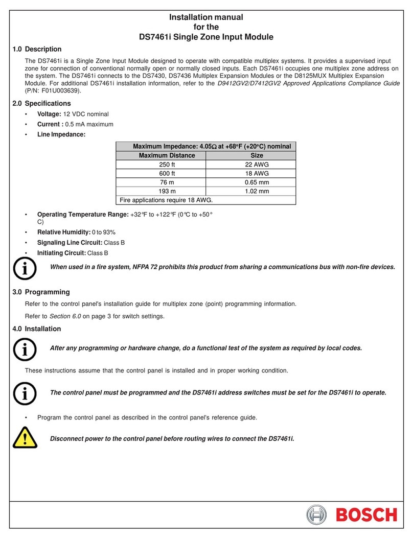
  9. Bosch Rexroth MKK 12-40 User manual

Bosch Rexroth MKK 12-40 User manual

The Drive & Control Company
Anleitung Linearmodule MKK/MKR/MLR
Instructions Linear Modules MKK/MKR/MLR
Instructions Modules linéaires MKK/MKR/MLR
Istruzioni Linearmoduli MKK/MKR/MLR
R320103918 (2010.07)
DE+EN+FR+IT
Wartung
Maintenance
Entretien
Manutenzione
Inbetriebnahme
Start-up
Mise en service
Messa in funzione
Montage
Mounting
Montage
Montaggio
2 Bosch Rexroth AG2 Bosch Rexroth AG Anleitung für Linearmodule MKK/MKR/MLR
1 Allgemeine Hinweise 6
1.1 Warnhinweise 6
1.2 Kennzeichnung von Verweisen 6
1.3 Symbole 6
1.4 Anziehdrehmomente 6
1.5 Sicherheitshinweise 8
1.6 Hinweise zu Transport und Lagerung 10
2. Übersicht Linearmodule 12
2.1 Typenübersicht 12
2.2 Daten auf dem Typenschild, Bestellung von
Verschleißteilen 12
2.3 Bestellung von Komponenten und
Druckschriften 12
3 Linearmodul befestigen 14
3.1 Linearmodul unterstützen 14
3.2 Spannstücke 14
3.3 Nutensteine 14
4 Übersicht Anbauteile 16
4.1 Schaltsystem und Antrieb: MKK/MKR 12-40 16
4.2 Schaltsystem und Antrieb: MKK/MKR 15-65,
MKK/MKR 20-80, MLR 10-80,
MKK/MKR 25-110, MLR 10-110,
MKK/MKR 35-165 18
5 Montage Schaltsystem mit
Magnetfeldsensoren: MKK/MKR 12-40 20
5.1 Hinweise 20
5.2 Magnetfeldsensor ohne Stecker mit
Befestigungskanal 20
5.3 Magnetfeldsensor mit Stecker und Kabelhaltern 24
6 Montage Schaltsystem mit induktiven
und mechanischen Schaltern:
alle Größen 26
6.1 Hinweise 26
6.2 Schaltwinkel montieren 26
6.3 Schalter montieren 26
6.4 Dose montieren 28
6.5 Kabelkanal montieren 30
7 Montage Antrieb MKK 32
7.1 Hinweise 32
7.2 Motor mit Kupplung montieren/demontieren 32
7.3 Motor mit Riemenvorgelege montieren/
demontieren 34
8 Montage Antrieb MKR/MLR 42
8.1 Hinweise 42
8.2 Motor montieren: MKR 15-65 und
MKR 35-165 mit Getriebe 42
7.3 Motor montieren: MKR 12-40, MKR 20-80,
MLR 10-80, MKR 25-110, MLR 10-110 44
8.4 Motor demontieren 46
9 Inbetriebnahme 48
9.1 Elektrische Anschlüsse 48
9.2 Probelauf, Einfahren 48
9.3 Betriebsbedingungen 48
10 Wartung 50
10.1 Wartungspunkte 50
10.2 Kugelgewindetrieb und Kugelschienenführung
schmieren (MKK) 50
10.3 Kugelschienenführung schmieren (MKR) 52
10.4 Laufrollenführungen ölen (MLR) 52
10.5 Bandabdeckung ölen 52
11 Übersicht Baugruppen (BG) MKK 54
11.1 Übersicht MKK 12-40 54
11.2 Übersicht MKK 15-65 56
11.3 Übersicht MKK 20-80, MKK 25-110 58
11.4 Übersicht MKK 35-165 60
12 Übersicht Baugruppen (BG) MKR 62
12.1 Übersicht MKR 12-40 62
12.2 Übersicht MKR 15-65 64
12.3 Übersicht MKR 20-80, MKR 25-110 66
12.4 Übersicht MKR 35-165 68
13 Übersicht Baugruppen (BG) MLR 70
13.1 Übersicht MLR 10-80, MLR 10-110 70
R320103918 (2010.07) • DE+EN+FR+IT
3Bosch Rexroth AG 3Bosch Rexroth AGInstructions for Linear Modules MKK/MKR/MLR
1 General notes 6
1.1 Warning notices 6
1.2 Referencing system 6
1.3 Symbols 6
1.4 Tightening torques 6
1.5 Safety instructions 8
1.6 Notes on transportation and storage 11
2. Overview of linear modules 13
2.1 Type range 13
2.2 Rating plate, ordering of wearing parts 13
2.3 Ordering of components and publications 13
3 Attachment of linear module 15
3.1 Supporting linear module 15
3.2 Securing linear module with clamping fixtures 15
3.3 Securing linear module with T-nuts 15
4 Attachments 17
4.1 Switching system and drive system:
MKK/MKR 12-40 17
4.2 Switching system and drive system:
MKK/MKR 15-65, MKK/MKR 20-80,
MLR 10-80, MKK/MKR 25-110, MLR 10-110,
MKK/MKR 35-165 19
5 Installing switching system with magnetic
field sensors: MKK/MKR 12-40 21
5.1 Notes 21
5.2 Magnetic field sensor without connector
with mounting duct 21
5.3 Magnetic field sensor with connector and
cable holders 25
6 Installing switching system with inductive
and mechanical switches: All sizes 27
6.1 Notes 27
6.2 Installing switching cams 27
6.3 Installing switches 27
6.4 Removing switches 27
6.5 Installing socket 29
6.6 Installing cable duct 31
7 Installing drive MKK 33
7.1 Notes 33
7.2 Installing/removing motor with motor mount
and coupling 33
7.3 Installing/removing motor with belt drive gear 35
8 Installing drive MKR/MLR 43
8.1 Notes 43
8.2 Installing motor: MKR 15-65 and MKR 35-165
with gear unit 43
8.3 Installing motor: MKR 12-40, MKR 20-80,
MLR 10-80, MKR 25-110, MLR 10-110 45
8.4 Removing motor 47
9 Start-up 49
9.1 Electrical connections 49
9.2 Trial run, run-in 49
9.3 Operating conditions 49
10 Maintenance 51
10.1 Maintenance items 51
10.2 Lubricating ball screw and ball rail system
(MKK) 51
10.3 Lubricating ball rail system (MKR) 53
10.4 Lubricating roller guides (MLR) 53
10.5 Lubricating cover strip 53
11 Overview of MKK assemblies (AS) 54
11.1 MKK 12-40 overview 54
11.2 MKK 15-65 overview 56
11.3 MKK 20-80, MKK 25-110 overview 58
11.4 MKK 35-165 overview 60
12 Overview of MKR assemblies (AS) 62
12.1 MKR 12-40 overview 62
12.2 MKR 15-65 overview 64
12.3 MKR 20-80, MKR 25-110 overview 66
12.4 MKR 35-165 overview 68
13 Overview of MLR assemblies (AS) 70
13.1 MLR 10-80, MLR 10-110 overview 70
R320103918 (2010.07) • DE+EN+FR+IT
4 Bosch Rexroth AG4 Bosch Rexroth AG Anleitung für Linearmodule MKK/MKR/MLR
1 Consignes générales 7
1.1 Consignes d’avertissement 7
1.2 Indications de références croisées 7
1.3 Symboles 7
1.4 Couples de serrage 7
1.5 Consignes de sécurité 9
1.6 Transport et stockage 11
2. Aperçu des modules linéaires 13
2.1 Aperçu des types 13
2.2 Plaque signalétique, commande de pièces
d’usure 13
2.3 Commande de composants et d’imprimés 13
3 Fixation du module linéaire 15
3.1 Soutien du module linéaire 15
3.2 Fixation du module linéaire par pièces de
bridage 15
3.3 Fixation du module linéaire par réglettes pour
rainures 15
4 Aperçu des accessoires 17
4.1 Système de commutation et entraînement :
MKK/MKR 12-40 17
4.2 Système de commutation et entraînement :
MKK/MKR 15-65, MKK/MKR 20-80,
MLR 10-80, MKK/MKR 25-110, MLR 10-110,
MKK/MKR 35-165 19
5 Montage du système de commutation
avec capteurs de champ magnétique :
MKK/MKR 12-40 21
5.1 Remarques 21
5.2 Capteur de champ magnétique sans fiche
avec chemin de câbles 21
5.3 Capteur de champ magnétique avec fiche et
supports de câbles 25
6 Système de commutation avec
interrupteurs inductifs et mécaniques :
toutes tailles 27
6.1 Remarques 27
6.2 Montage de l’équerre de commande 27
6.3 Montage des interrupteurs 27
6.4 Démontage des interrupteurs 27
6.5 Montage de la prise 29
6.6 Montage du chemin de câbles 31
7 Montage de l’entraînement MKK 33
7.1 Remarques 33
7.2 Montage/démontage du moteur à bride et
accouplement 33
7.3 Montage/démontage du moteur à renvoi par
poulies et courroie 35
8 Montage de l’entraînement MKR/MLR 43
8.1 Remarques 43
8.2 Montage du moteur : MKR 15-65 et
MKR 35-165 avec réducteur 43
8.3 Montage du moteur : MKR 12-40,
MKR 20-80, MLR 10-80, MKR 25-110,
MLR 10-110 45
8.4 Démontage du moteur 47
9 Mise en service 49
9.1 Raccordements électriques 49
9.2 Essai de fonctionnement, rodage 49
9.3 Conditions de fonctionnement 49
10 Entretien 51
10.1 Points d’entretien 51
10.2 Lubrification de la vis à billes et du guidage
à billes sur rails (MKK) 51
10.3 Lubrification du guidage à billes sur rails
(MKR) 53
10.4 Huiler les guidages à rouleaux (MLR) 53
10.5 Huilage de la bande de recouvrement 53
11 Aperçu des ensembles (E) MKK 54
11.1 Aperçu MKK 12-40 54
11.2 Aperçu MKK 15-65 56
11.3 Aperçu MKK 20-80, MKK 25-110 58
11.4 Aperçu MKK 35-165 60
12 Aperçu des ensembles (E) MKR 62
12.1 Aperçu MKR 12-40 62
12.2 Aperçu MKR 15-65 64
12.3 Aperçu MKR 20-80, MKR 25-110 66
12.4 Aperçu MKR 35-165 68
13 Aperçu des ensembles (E) MLR 70
13.1 Aperçu MLR 10-80, MLR 10-110 70
R320103918 (2010.07) • DE+EN+FR+IT
5Bosch Rexroth AG 5Bosch Rexroth AGInstructions for Linear Modules MKK/MKR/MLR
1 Avvertenze generali 7
1.1 Segnali 7
1.2 Segni grafici di rimando 7
1.3 Simboli 7
1.4 Coppie di serraggio 7
1.5 Avvertenze per la sicurezza 9
1.6 Avvertenze relative al trasporto e al
magazzinaggio 11
2. Panoramica Linearmoduli 13
2.1 Panoramica dei tipi 13
2.2 Targhetta di identificazione, ordinazione
di parti soggette ad usura 13
2.3 Ordinazione dei componenti e della
documentazione 13
3 Fissaggio del Linearmodulo 15
3.1 Sostegno del Linearmodulo 15
3.2 Fissaggio del Linearmodulo con staffe di
fissaggio 15
3.3 Fissaggio del Linearmodulo con inserti filettati 15
4 Panoramica interruttori 17
4.1 Sistema di commutazione:
MKK/MKR 12-40 17
4.2 Sistema di commutazione:
MKK/MKR 15-65, MKK/MKR 20-80,
MLR 10-80, MKK/MKR 25-110, MLR 10-110,
MKK/MKR 35-165 19
5 Montaggio dei sensori di campo
magnetico: MKK/MKR 12-40 21
5.1 Avvertenze 21
5.2 Sensore di campo magnetico senza
connettore con canalina di fissaggio 21
5.3 Sensore di campo magnetico con connettore
e fermacavo 25
6 Montaggio di interruttori induttivi
e meccanici: tutte le dimensioni 27
6.1 Avvertenze 27
6.2 Montaggio della camma di commutazione 27
6.3 Montaggio degli interruttori 27
6.4 Smontaggio degli interruttori 27
6.5 Montaggio della presa 29
6.6 Montaggio della canalina cavi 31
7 Montaggio del motore: MKK 33
7.1 Avvertenze 33
7.2 Montaggio/smontaggio del motore con
flangia e giunto 33
7.3 Montaggio/smontaggio del motore con
elemento di rinvio cinghia 35
8 Montaggio del motore: MKR/MLR 43
8.1 Avvertenze 43
8.2 Montaggio del motore: MKR 15-65 e
MKR 35-165 con riduttore 43
8.3 Montaggio del motore: MKR 12-40,
MKR 20-80, MLR 10-80, MKR 25-110,
MLR 10-110 45
8.4 Smontaggio del motore 47
9 Messa in funzione 49
9.1 Collegamenti elettrici 49
9.2 Funzionamento di prova, rodaggio 49
9.3 Condizioni di esercizio 49
10 Manutenzione 51
10.1 Punti di manutenzione 51
10.2 Lubrificazione della vite a sfere e
della guida a sfere su rotaia (MKK) 51
10.3 Lubrificazione della guida a sfere su
rotaia (MKR) 53
10.4 Lubrificazione delle guide a rotelle di
scorrimento (MLR) 53
10.5 Lubrificazione a olio del nastro di copertura 53
11 Panoramica gruppi di componenti
(GC) MKK 54
11.1 Panoramica MKK 12-40 54
11.2 Panoramica MKK 15-65 56
11.3 Panoramica MKK 20-80, MKK 25-110 58
11.4 Panoramica MKK 35-165 60
12 Panoramica gruppi di componenti
(GC) MKR 62
12.1 Panoramica MKR 12-40 62
12.2 Panoramica MKR 15-65 64
12.3 Panoramica MKR 20-80, MKR 25-110 66
12.4 Panoramica MKR 35-165 68
13 Panoramica gruppi di componenti
(GC) MLR 70
13.1 Panoramica MLR 10-80, MLR 10-110 70
R320103918 (2010.07) • DE+EN+FR+IT
μ= 0,125 M2 M2,5 M3 M4 M5 M6 M8 M10 M12
MA
max.
(Nm)
8.8 0,4 0,7 1,3 2,8 5,6 9,6 23 46 79
μ= 0.125 M2 M2,5 M3 M4 M5 M6 M8 M10 M12
MA
max.
(Nm)
8.8 0.4 0.7 1.3 2.8 5.6 9.6 23 46 79
6 Bosch Rexroth AG6 Bosch Rexroth AG Anleitung für Linearmodule MKK/MKR/MLR
ii
1 General notes
1.1 Warning notices
Use is made of the following warning notices:
DANGER!
Risk of fatal injury from contact with
live parts! Deenergize the unit! Make
sure the unit is deenergized! Provide
safeguards to prevent unintentional or
unauthorized re-connection of the power
supply! Ground and short-circuit the unit!
Cover over or cordon off live parts of the
system!
WARNING!
Risk of injury!
Caution!
Risk of damage to linear system
or adjacent structures!
Caution!
Keep the linear system clean!
Cover over if necessary!
1.2 Referencing system
The following symbols are used to make reference to recurring
or further operations:
• Dot: Instruction
– Dash: List
!6.1 Refer to Section 6.1
!⌧6.1.2 Refer to Fig. 6.1.2
(Fig. 2 in Section 6.1)
fNote, recommendation
1.3 Symbols
Bolt, screw
Tightening torque
Clean!
Heed further information in the catalog.
1.4 Tightening torques
Use is made of bolts of strength class 8.8 as standard.
Any divergence from this is indicated accordingly.
1 Allgemeine Hinweise
1.1 Warnhinweise
Folgende Warnhinweise werden verwendet:
GEFAHR!
Lebensgefahr beim Berühren spannungs-
führender Teile! Gerät spannungsfrei ma-
chen! Spannungsfreiheit prüfen! Strom-
versorgung gegen unbeabsichtigtes oder
unbefugtes Wiedereinschalten sichern!
Erden und kurzschließen! Spannungs-
führende Anlagenteile abdecken oder
abschranken!
WARNUNG!
Verletzungsgefahr!
Achtung!
Gefahr für Linearsystem
oder Anschlusskonstruktion!
Achtung!
Linearsystem sauber halten!
Wenn nötig abdecken!
1.2 Kennzeichnung von Verweisen
Auf wiederkehrende oder weiterführende Arbeitsgänge wird wie
folgt verwiesen:
• Punkt: Handlungsanweisung
– Spiegelstrich: Aufzählung
!6.1 Siehe Abschnitt 6.1
!⌧6.1.2 Siehe Bild 6.1.2
(Bild 2 im Abschnitt 6.1)
fHinweis, Tipp
1.3 Symbole
Schraube
Anziehdrehmoment
Reinigen!
Weitere Informationen im Katalog beachten.
1.4 Anziehdrehmomente
Standardmäßig werden Schrauben der Festigkeitsklasse 8.8
verwendet. Abweichungen sind entsprechend gekennzeichnet.
R320103918 (2010.07) • DE+EN+FR+IT
μ= 0,125 M2 M2,5 M3 M4 M5 M6 M8 M10 M12
MA
máx.
(Nm)
8.8 0,4 0,7 1,3 2,8 5,6 9,6 23 46 79
μ= 0,125 M2 M2,5 M3 M4 M5 M6 M8 M10 M12
MA
máx.
(Nm)
8.8 0,4 0,7 1,3 2,8 5,6 9,6 23 46 79
7Bosch Rexroth AG 7Bosch Rexroth AGInstructions for Linear Modules MKK/MKR/MLR
ii
1 Avvertenze generali
1.1 Segnali
Vengono utilizzati i seguenti segnali:
PERICOLO!
Pericolo di morte in caso di contatto con
le parti sotto tensione! Staccare l’appa-
recchio dalla corrente elettrica! Verificare
l’assenza di tensione! Adottare misure
opportune per impedire il reinserimento
accidentale o non autorizzato dell’ali-
mentazione elettrica! Collegare a massa
e mettere in cortocircuito l'apparecchio!
Coprire o transennare eventuali parti sotto
tensione dell’impianto!
AVVERTIMENTO!
Pericolo di lesioni!
Attenzione!
Pericolo per il sistema lineare
o per le parti collegate!
Attenzione!
Mantenere pulito il sistema lineare!
All’occorrenza provvedere alla copertura!
1.2 Segni grafici di rimando
Le operazioni ricorrenti o successive vengono indicate con
i seguenti simboli di rimando:
• Punto: istruzione
– Trattino: elenco
!6.1 Vedi paragrafo 6.1
!⌧6.1.2 Vedi figura 6.1.2
(figura 2 nel paragrafo 6.1)
fInformazione, suggerimento
1.3 Simboli
Vite
Coppia di serraggio
Provvedere alla pulizia!
Osservare le ulteriori informazioni
contenute nel catalogo.
1.4 Coppie di serraggio
Come standard vengono utilizzate viti della classe di resistenza 8.8.
Eventuali scostamenti sono opportunamente contrassegnati.
1 Consignes générales
1.1 Consignes d’avertissement
Les consignes d’avertissement suivantes sont utilisées :
DANGER !
Danger de mort en cas de contact avec
des pièces sous tension ! Couper la
tension de l’appareil ! S’assurer que
l’appareil est hors tension ! Empêcher
toute mise sous tension inopinée ou
non autorisée ! Mettre à la terre et
court-circuiter ! Recouvrir les éléments
conducteurs ou les isoler par une
barrière !
AVERTISSEMENT !
Risque de blessures !
Attention !
Danger pour le système linéaire
ou pour les éléments périphériques !
Attention !
Le système linéaire doit toujours être
propre !
Le recouvrir si nécessaire !
1.2 Indications de références croisées
Les indications suivantes sont utilisées pour marquer les
opérations répétitives ou antérieures à d’autres opérations :
• Point : instruction
– Tiret : énumération
!6.1 Voir la section 6.1
!⌧6.1.2 Voir la figure 6.1.2
(Figure 2 de la section 6.1)
fInformation, conseil
1.3 Symboles
Vis
Couple de serrage
Nettoyer !
Tenir compte des informations
supplémentaires figurant dans le catalogue.
1.4 Couples de serrage
Nous utilisons en standard des vis de la classe de résistance 8.8.
Les divergences sont indiquées en conséquence.
R320103918 (2010.07) • DE+EN+FR+IT
8 Bosch Rexroth AG8 Bosch Rexroth AG Anleitung für Linearmodule MKK/MKR/MLR
1.5 Safety instructions
Intended use
cWARNING!
Operation of the linear system not in compliance with the
intended use can lead to accidents involving injury and
damage as well as to production stoppages!
• Heed all the pertinent safety regulations as regards the
design of adjacent structures, e.g. DIN EN ISO 12100
(machine safety).
• Above and beyond this always observe the generally
accepted rules of engineering practice.
• Before starting up the machine in which the linear system is
installed: Make sure all the necessary safety devices have
been installed and are functioning properly.
General notes on installation
cRexroth linear systems are only to be installed,
started up and maintained by appropriately qualified
personnel, e. g. mechatronics engineers in accordance with
the specifications contained in this manual.
WARNING!
Risk of injury from sharp edges!
• Wear suitable protective gloves when performing installation
work.
cCaution!
Risk of damage to the linear system or adjacent structures!
• Always perform installation work carefully and
conscientiously as specified in this manual.
• Have a second person assist with heavy elements and
provide adequate support.
Start-up
iDANGER!
Risk of fatal injury from contact with live parts!
• Deenergize the unit!
• Make sure the unit is deenergized!
• Provide safeguards to prevent unintentional or unauthorized
re-connection of the power supply!
• Ground and short-circuit the unit!
• Cover over or cordon off live parts of the system!
cCaution!
Prior to initial start-up of the linear system:
• Perform test runs under realistic production conditions.
Never start up the installation with the linear system until at
least one test run has been successfully completed.
• Check the tightness of all bolted joints.
1.5 Sicherheitshinweise
Bestimmungsgemäße Verwendung
cWARNUNG!
Nicht bestimmungsgemäßer Gebrauch des Linearsystems
kann zu Unfällen mit Personen- und Sachschäden sowie zu
Produktionsausfällen führen!
• Bei der Gestaltung der Anschlusskonstruktion alle ein-
schlägigen Sicherheitsvorschriften beachten, z.B. DIN EN
ISO 12100 (Sicherheit von Maschinen).
• Darüber hinaus die allgemein anerkannten Regeln der Tech-
nik beachten.
• Bevor die Maschine, in der das Linearsystem eingebaut ist,
in Betrieb genommen wird: Sicherstellen, dass alle erforder-
lichen Schutzvorrichtungen installiert und wirksam sind.
Montage allgemein
cRexroth Linearsysteme nach den Angaben in dieser
Anleitung und nur von einschlägig qualifiziertem Personal
montieren, in Betrieb nehmen und warten lassen, z. B.
durch Mechatroniker.
WARNUNG!
Verletzungsgefahr durch scharfe Kanten!
• Während der Montage geeignete Schutzhandschuhe tragen.
cAchtung!
Gefahr für das Linearsystem oder die Anschlusskonstruk-
tion!
• Montage stets mit großer Sorgfalt und Konzentration gemäß
dieser Anleitung ausführen.
• Bei schweren Bauelementen zu zweit arbeiten und für aus-
reichende Abstützung sorgen.
Inbetriebnahme
iGEFAHR!
Lebensgefahr beim Berühren spannungsführender Teile!
• Gerät spannungsfrei machen!
• Spannungsfreiheit prüfen!
• Stromversorgung gegen unbeabsichtigtes oder unbefugtes
Wiedereinschalten sichern!
• Erden und kurzschließen!
• Spannungsführende Anlagenteile abdecken oder abschran-
ken!
cAchtung!
Vor der ersten Inbetriebnahme des Linearsystems:
• Testläufe unter produktionsnahen Bedingungen durchführen.
Anlage mit dem Linearsystem erst in Betrieb nehmen, wenn
mindestens ein erfolgreicher Testlauf absolviert wurde.
• Alle Schraubverbindungen auf Festsitz prüfen.
R320103918 (2010.07) • DE+EN+FR+IT
9Bosch Rexroth AG 9Bosch Rexroth AGInstructions for Linear Modules MKK/MKR/MLR
1.5 Avvertenze per la sicurezza
Uso conforme alle prescrizioni
cAVVERTIMENTO!
Un uso non conforme alle prescrizioni del sistema lineare
può causare incidenti con danni a persone o materiali
nonché perdite di produzione!
• In fase di progettazione delle parti collegate si devono
rispettare tutte le norme di sicurezza pertinenti, ad es.
DIN EN ISO 12100 (Sicurezza delle macchine).
• Inoltre vanno rispettate tutte le regole della tecnica
generalmente riconosciute.
• Prima di procedere alla messa in funzione della macchina
nella quale il sistema lineare è montato, assicurarsi che tutti i
necessari dispositivi di protezione siano installati ed efficaci.
Montaggio in generale
cFar eseguire il montaggio, la messa in funzione e la
manutenzione dei sistemi lineari Rexroth conformemente
alle indicazioni contenute nelle presenti istruzioni e solo
da parte di personale qualificato che dispone di idonea
formazione, ad es. tecnici meccatronici.
AVVERTIMENTO!
Pericolo di lesioni a causa di spigoli taglienti!
• Durante il montaggio indossare guanti protettivi idonei.
cAttenzione!
Pericolo per il sistema lineare o per le parti collegate!
• Eseguire il montaggio sempre con la massima diligenza e
concentrazione, attenendosi alle presenti istruzioni.
• In caso di elementi costruttivi pesanti, lavorare in due e
assicurare un sostegno sufficiente.
Messa in funzione
iPERICOLO!
Pericolo di morte in caso di contatto con le parti sotto
tensione!
• Staccare l’apparecchio dalla corrente elettrica!
• Verificare l’assenza di tensione!
• Adottare misure opportune per impedire il reinserimento
accidentale o non autorizzato dell’alimentazione elettrica!
• Collegare a massa e mettere in cortocircuito l'apparecchio!
• Coprire o transennare eventuali parti sotto tensione
dell’impianto!
cAttenzione!
Prima della messa in funzione iniziale del sistema lineare:
• Effettuare dei test di funzionamento con condizioni simili a
quelle di produzione. Mettere in funzione l’impianto con il
sistema lineare solo se almeno uno dei test di funzionamento
si è concluso con successo.
• Verificare il saldo accoppiamento di tutti i collegamenti a vite.
1.5 Consignes de sécurité
Utilisation conforme
cAVERTISSEMENT !
Une utilisation non conforme du système linéaire peut être
source d’accidents corporels et de dommages matériels
ainsi que d’arrêts de la production !
• Pour la configuration des éléments périphériques, observer
la totalité des consignes de sécurité en vigueur, par ex.
DIN EN ISO 12100 (Sécurité des machines).
• Observer également les règles généralement reconnues de
la technique.
• Avant de mettre en service la machine dans laquelle est
monté le système linéaire, s’assurer que tous les dispositifs
de protection nécessaires sont installés et opérationnels.
Montage, généralités
cLe montage, la mise en service et l’entretien
des systèmes linéaires Rexroth doivent être effectués
conformément aux indications données dans les présentes
instructions, et uniquement par un personnel qualifié, par
ex. un mécatronicien.
AVERTISSEMENT !
Risque de blessure par les arêtes vives !
• Porter des gants de protection appropriés pendant le
montage.
cAttention !
Danger pour le système linéaire ou les éléments
périphériques !
• Le montage doit être effectué avec grand soin et
concentration, conformément aux présentes instructions.
• Dans le cas des éléments lourds, travailler à deux et assurer
un soutien suffisant.
Mise en service
iDANGER !
Danger de mort en cas de contact avec des pièces sous
tension !
• Couper la tension de l’appareil !
• S’assurer que l’appareil est hors tension !
• Empêcher toute mise sous tension inopinée ou non
autorisée !
• Mettre à la terre et court-circuiter !
• Recouvrir les éléments conducteurs ou les isoler par une
barrière !
cAttention !
Avant la première mise en service du système linéaire :
• Effectuer des tests de fonctionnement dans des conditions
proches de celles de la production. Ne mettre l’installation
avec le système linéaire en service que si au moins un test
de fonctionnement s’est déroulé avec succès.
• Vérifier le bon serrage de tous les vissages.
R320103918 (2010.07) • DE+EN+FR+IT
A
B
1.3
L
LLL
2/7
2/73/7
L
LLLLL
1/91/9
2/9
3/9
2/9
10 Bosch Rexroth AG Anleitung für Linearmodule MKK/MKR/MLR
L ≤2000mm
L >2000mm
1.6 Hinweise zu Transport und
Lagerung
Rexroth Linearmodule werden einbaufer-
tig vormontiert geliefert.
WARNUNG!
Verletzungsgefahr durch hohes Ge-
wicht! Je nach Größe und Länge des
Linearmoduls geeignetes Hebewerk-
zeug verwenden!
Gewichtsberechnung siehe Katalog
Linearmodule.
cAchtung!
Beim Anheben und Transportieren das
Linearmodul nur gemäß Abbildung A
oder B belasten. Längen beachten.
Endköpfe und Spindelzapfen nicht
belasten.
Keinesfalls nur in der Mitte oder nur
an den Enden aufhängen!
Linearmodul in überdachtem,
trockenem Raum lagern. Vor Feuchtig-
keit und korrosiven Einflüssen schüt-
zen.
R320103918 (2010.07) • DE+EN+FR+IT
11Bosch Rexroth AGInstructions for Linear Modules MKK/MKR/MLR
1.6 Avvertenze relative al
trasporto e al magazzinaggio
I Linearmoduli Rexroth vengono forniti
preassemblati, pronti per il montaggio.
AVVERTIMENTO!
Pericolo di lesioni a causa del peso
elevato! A seconda delle dimensioni
e della lunghezza del Linearmodulo,
utilizzare dispositivi di sollevamento
idonei!
Per il calcolo del peso, vedi il catalogo
dei Linearmoduli.
cAttenzione!
Durante il sollevamento e il trasporto
sollecitare il Linearmodulo solo
secondo quanto indicato nella
figura A o B. Prestare attenzione alle
lunghezze. Non sollecitare le testate
terminali.
In nessun caso effettuare l’aggancio
solo al centro o solo alle estremità!
Conservare il Linearmodulo in un
locale chiuso e asciutto. Proteggerlo
dall’umidità e da influssi corrosivi.
1.6 Transport et stockage
Les modules linéaires Rexroth sont livrés
prêts à monter.
AVERTISSEMENT !
Danger de blessure découlant du
poids élevé ! Suivant la taille et la
longueur du module linéaire, utiliser
un engin de levage approprié !
Voir le catalogue de modules linéaires
pour le calcul du poids.
cAttention !
Lors du levage et du transport, ne
charger le module linéaire que d’après
la figure A ou B. Tenir compte des
longueurs. Ne pas charger les têtes
d’extrémité et les tourillons de broche.
Ne jamais suspendre uniquement au
milieu ou aux extrémités !
Stocker le module linéaire dans
un local couvert et sec. Le protéger
de l’humidité et des facteurs de
corrosion.
1.6 Notes on transportation and
storage
Rexroth linear modules are supplied
pre-assembled ready for installation.
WARNING!
Risk of injury from heavy weights! Use
suitable lifting gear appropriate to the
size and length of the linear module!
Refer to the Linear Modules catalog
for weight calculations.
cCaution!
For lifting and transportation,
make sure the linear module is
only subjected to load as shown in
Fig. A or Fig. B. Observe the length
specifications. Do not subject end
blocks and spindle ends to load.
Never suspend just in the center or
just at the ends!
Linear modules are to be stored
in enclosed dry premises. Guard
against moisture and corrosion.
R320103918 (2010.07) • DE+EN+FR+IT
2.2
2.1
H
LA
1
2
3
4
A
(mm)
H
(mm)
MKK 12-40 40 52
MKR 12-40
MKK 15-65
MKR 15-65
65 85
MKK 20-80
MKR 20-80
MLR 10-80
80 100
MKK 25-110
MKR 25-110
MLR 10-110
110 129
MKK 35-165
MKR 35-165
165 195
12 Bosch Rexroth AG Anleitung für Linearmodule MKK/MKR/MLR
2. Übersicht Linearmodule
2.1 Typenübersicht
Die Linearmodule sind in fünf Baugrößen
erhältlich. Genaue Daten und Maße siehe
aktuelle Kataloge.
2.2 Typenschild, Bestellung von
Verschleißteilen
1 Materialnummer* des Linearmoduls
2 Seriennummer
3 Kundenauftragsnummer
4 Fertigungsdatum
• Bei Bestellung von Verschleißteilen
bitte unbedingt alle Daten auf dem
Typenschild angeben.
* Die „Materialnummer“ kann in anderen
Druckschriften auch „Teilenummer“
heißen.
2.3 Bestellung von Komponenten
und Druckschriften
• Für die Bestellung von Komponenten
siehe Katalog „Linearmodule“ sowie
Kataloge für Antriebsregler.
fDie Kataloge ergänzen diese An-
leitung und sollten daher bereitgehalten
werden.
• Aktuelle Druckschriften bitte bei Ihrem
Vertriebspartner bestellen oder Down-
load unter www.boschrexroth.com/
medienverzeichnis.
R320103918 (2010.07) • DE+EN+FR+IT
13Bosch Rexroth AGInstructions for Linear Modules MKK/MKR/MLR
2. Panoramica Linearmoduli
2.1 Panoramica dei tipi
I Linearmoduli sono disponibili in cinque
dimensioni costruttive. Per le misure ed i
dati precisi, consultare i cataloghi attuali.
2.2 Targhetta di identificazione,
ordinazione di parti soggette
ad usura
1 Numero di ordinazione* del
Linearmodulo
2 Numero di serie
3 Numero d’ordine del cliente
4 Data di fabbricazione
• In fase di ordinazione delle parti
soggette ad usura, indicare assoluta-
mente tutti i dati riportati sulla
targhetta di identificazione.
* In altre pubblicazioni il "numero di
ordinazione" può essere denominato
anche come "numero pezzo".
2.3 Ordinazione dei componenti
e della documentazione
• Per l’ordinazione di componenti, vedi
il catalogo "Linearmoduli" nonché i
cataloghi per gli azionamenti digitali.
fI cataloghi integrano il presente
manuale e pertanto dovrebbero essere
tenuti a portata di mano.
• La documentazione aggiornata può
essere ordinata presso il proprio
partner commerciale oppure scaricata
all’indirizzo www.boschrexroth.com/
mediadirectory.
2. Aperçu des modules
linéaires
2.1 Aperçu des types
Les modules linéaires sont disponibles
en cinq tailles. Voir les catalogues pour
les données et les cotes précises.
2.2 Plaque signalétique,
commande de pièces d’usure
1 Référence* du module linéaire
2 Numéro de série
3 Numéro de commande client
4 Date de fabrication
• Toujours indiquer les données figurant
sur la plaque signalétique lors de la
commande de pièces d’usure.
* La « Référence » peut également être
appelée « Numéro de pièce » dans
d’autres documents.
2.3 Commande de composants
et d’imprimés
• Pour la commande de composants,
voir le catalogue « Modules linéaires »
de même que les catalogues de
régulateurs d’entraînement.
fLes catalogues complètent ces
instructions et doivent de ce fait être
tenus à disposition.
• Veuillez commander les imprimés
actuels auprès de votre distributeur
ou les télécharger sous
www.boschrexroth.com/
mediadirectory.
2. Overview of linear modules
2.1 Type range
Five different sizes of linear module are
available. Refer to the latest catalogs for
precise data and dimensions.
2.2 Rating plate, ordering of
wearing parts
1 Material number* of linear module
2 Serial number
3 Customer order number
4 Date of manufacture
• Please quote all data on the rating
plate when ordering wearing parts.
* In other publications, the "Material
number" may also be referred to as
"Part number".
2.3 Ordering of components and
publications
• For ordering components, refer to
the "Linear Modules" catalog and the
catalogs for drive controllers.
fThe catalogs provide extra
information and should therefore always
be kept to hand.
• The latest publications can be ordered
from your dealer or downloaded from
www.boschrexroth.com/
mediadirectory.
R320103918 (2010.07) • DE+EN+FR+IT
A±0,1
B
3.2
A
B
min. 5 mm
fmax F
300 mm 300 mm 300 mm 300 mm
3.1
3.3
C
12
3
MKK/MKR/MLR A
(mm)
B
(mm)
12-40 52,2 65,5 M5
15-65 81 95 M6
20-80/10-80 96 110 M6
25-110/10-110 132 150 M8
35-165 192 218 M10
MKK/MKR/MLR C
(mm)
25-110 85
10-110 85
35-165 120
14 Bosch Rexroth AG Anleitung für Linearmodule MKK/MKR/MLR
3 Linearmodul befestigen
Beim Anziehen der Schrauben Anzieh-
drehmomente !1.4 beachten.
3.1 Linearmodul unterstützen
cAchtung!
Linearmodul nicht an den Endplatten
unterstützen: Abstand mindestens
5 mm (A)!
Maximal zulässige Durchbiegung
fmax beachten (siehe Diagramme im
Katalog)!
Bei hohen Anforderungen an die
Systemdynamik alle 300 mm unter-
stützen (B)!
fBeachten Sie auch das spezielle
Verbindungssystem für Linearmodule.
3.2 Linearmodul mit Spannstü-
cken befestigen
Alle Linearmodule können mit Spannstü-
cken befestigt werden.
Empfohlene Anzahl pro Seite:
1 6 Stück/m
2 4 Stück/m
3 3 Stück/m
– Bestellung nur unter Angabe der
Materialnummer möglich
fIn den Spannstücken sind Sen-
kungen für Schrauben nach ISO 4762.
3.3 Linearmodul mit Nutenstei-
nen befestigen
Die Linearmodule MKK/MKR 25-110,
MLR 10-110 und MKK/MKR 35-165 kön-
nen mit Nutensteinen befestigt werden.
– Empfohlene Anzahl pro Seite:
6 Stück/m
– Passende Nutensteine können über
Bosch Rexroth bezogen werden, siehe
Katalog „Linearmodule“
R320103918 (2010.07) • DE+EN+FR+IT
15Bosch Rexroth AGInstructions for Linear Modules MKK/MKR/MLR
3 Fissaggio del
Linearmodulo
In fase di serraggio rispettare le
coppie di serraggio !1.4.
3.1 Sostegno del Linearmodulo
cAttenzione!
Non sostenere il Linearmodulo in
corrispondenza delle testate terminali:
distanza almeno 5 mm (A)!
Prestare attenzione alla massima
inflessione ammessa fmax (vedi i
diagrammi nel catalogo)!
In presenza di sollecitazioni eccessive
alla dinamica del sistema prevedere
un sostegno ogni 300 mm (B)!
fPrestare attenzione anche al
sistema di collegamento speciale per
Linearmoduli.
3.2 Fissaggio del Linearmodulo
con staffe di fissaggio
Tutti i Linearmoduli possono essere
fissati tramite staffe di fissaggio.
Numero raccomandato per ogni lato:
1 6 pezzi/m
2 4 pezzi/m
3 3 pezzi/m
– Per l’ordinazione è necessario indicare
il codice del componente
fLe staffe di fissaggio sono dotate
di svasature per viti a norma ISO 4762.
3.3 Fissaggio del Linearmodulo
con inserti filettati
I Linearmoduli MKK/MKR 25-110,
MLR 10-110 e MKK/MKR 35-165
possono essere fissati con inserti filettati.
– Numero raccomandato per ogni lato:
6 pezzi/m
– Inserti filettati idonei possono essere
acquistati presso Bosch Rexroth, vedi
il catalogo "Linearmoduli"
MKK/MKR/MLR C
(mm)
25-110 85
10-110 85
35-165 120
MKK/MKR/MLR A
(mm)
B
(mm)
12-40 52,2 65,5 M5
15-65 81 95 M6
20-80/10-80 96 110 M6
25-110/10-110 132 150 M8
35-165 192 218 M10
3 Fixation du module
linéaire
Lors du serrage des vis, observer les
couples de serrage !1.4.
3.1 Soutien du module linéaire
cAttention !
Ne pas soutenir le module linéaire
aux plaques d’extrémité : distance
minimale 5 mm (A) !
Observer la flexion maximale
admissible fmax (voir les diagrammes
dans le catalogue) !
En cas de sollicitations dynamiques
importantes, soutenir tous les
300 mm (B) !
fObserver également le système de
liaison spécial pour modules linéaires.
3.2 Fixation du module linéaire
par pièces de bridage
Tous les modules linéaires peuvent être
fixés à l’aide de pièces de bridage.
Nombre recommandé par côté :
1 6 pièces/m
2 4 pièces/m
3 3 pièces/m
– L’indication de la référence est
indispensable pour toute commande.
fLes pièces de bridage sont munies
de lamages pour les vis selon ISO 4762.
3.3 Fixation du module linéaire
par réglettes pour rainures
Les modules linéaires MKK/MKR 25-110,
MLR 10-110 et MKK/MKR 35-165
peuvent être fixés à l’aide de réglettes
pour rainures.
– Nombre recommandé par côté :
6 pièces/m
– Des réglettes pour rainures
appropriées sont disponibles auprès
de Bosch Rexroth, voir le catalogue
« Modules linéaires »
MKK/MKR/MLR C
(mm)
25-110 85
10-110 85
35-165 120
MKK/MKR/MLR A
(mm)
B
(mm)
12-40 52,2 65,5 M5
15-65 81 95 M6
20-80/10-80 96 110 M6
25-110/10-110 132 150 M8
35-165 192 218 M10
3 Attachment of linear
module
When tightening the bolts, pay atten-
tion to the tightening torques !1.4.
3.1 Supporting linear module
cCaution!
Never support the linear module at the
end plates: Maintain a clearance of at
least 5 mm (A)!
Heed the maximum permissible
deflection fmax (refer to graphs in
catalog)!
Provide support at 300 mm intervals
in the case of exacting demands with
regard to system dynamics (B)!
fAlso note the special connection
system for linear modules.
3.2 Securing linear module with
clamping fixtures
All linear modules can be secured using
clamping fixtures.
Recommended number per side:
1 6 per meter
2 4 per meter
3 3 per meter
– Material number must be stated when
ordering
fThe clamping fixtures are provided
with counterbores for screws as per
ISO 4762.
3.3 Securing linear module with
T-nuts
The linear modules MKK/MKR 25-110,
MLR 10-110 and MKK/MKR 35-165 can
be secured using T-nuts.
– Recommended number per side:
6 per meter
– Suitable T-nuts can be obtained
from Bosch Rexroth (refer to "Linear
Modules" catalog)
MKK/MKR/MLR C
(mm)
25-110 85
10-110 85
35-165 120
MKK/MKR/MLR A
(mm)
B
(mm)
12-40 52,2 65,5 M5
15-65 81 95 M6
20-80/10-80 96 110 M6
25-110/10-110 132 150 M8
35-165 192 218 M10
R320103918 (2010.07) • DE+EN+FR+IT
4.1
13
5
2
1
3
4
6
7
12
8
9
10
11
11
13
12
13
12
12
14
15
12
15
12
2
1
3
6
7
8
10 9
4
MKK
MKK
MKK
MKR
MKR
MKR
16 Bosch Rexroth AG Anleitung für Linearmodule MKK/MKR/MLR
4 Übersicht Anbauteile
fAuf Wunsch können folgende
Komponenten bei Bosch Rexroth einsatz-
fertig montiert werden. Nachrüstung ist
ebenfalls jederzeit möglich.
4.1 Schaltsystem und Antrieb:
MKK/MKR 12-40
Schaltsysteme mit Magnetfeldsen-
soren !5
Magnetfeldsensor mit Stecker und Kabel-
haltern:
1 Magnetfeldsensor mit Stecker
2 Sensorhalter
3 Kabelhalter
4 Dose mit Stecker
Magnetfeldsensor mit Befestigungskanal:
5Magnetfeldsensor mit fest eingegos-
senem Kabel
6Befestigungskanal
7Dose mit Stecker
Schaltsystem mit induktiven Schal-
tern !6
8Schalter
9Schaltwinkel
10 Befestigungskanal
11 Dose mit Stecker
Antrieb !7
12 Motor
13 Vorsatzgetriebe (nur MKR)
14 Riemenvorgelege (nur MKK)
15 Flansch und Kupplung (nur MKK)
R320103918 (2010.07) • DE+EN+FR+IT
17Bosch Rexroth AGInstructions for Linear Modules MKK/MKR/MLR
4 Panoramica interruttori
fSu richiesta i seguenti componenti
possono essere assemblati pronti per
l’uso presso Bosch Rexroth. Anche
l’equipaggiamento a posteriori è possibile
in qualsiasi momento.
4.1 Sistema di commutazione:
MKK/MKR 12-40
Sistemi di commutazione con sensori
di campo magnetico !5
Sensore di campo magnetico con spina
e fermacavo:
1 Sensore di campo magnetico con
connettore
2 Supporto sensore
3 Fermacavo
4 Presa con connettore
Sensore di campo magnetico con
canalina di fissaggio:
5Sensore di campo magnetico con
cavo incorporato
6Canalina di fissaggio
7Presa con connettore
Sistema di commutazione con
interruttori induttivi !6
8Interruttore
9Camma di commutazione
10 Canalina di fissaggio
11 Presa con connettore
Azionamento !7
12 Motore
13 Riduttore (solo MKR)
14 Elemento di rinvio cinghia (solo MKK)
15 Flangia e giunto (solo MKK)
4 Aperçu des accessoires
fLes composants suivants peuvent
être montés sur demande chez Bosch
Rexroth. Un rééquipement est également
possible à tout moment.
4.1 Système de commutation et
entraînement :
MKK/MKR 12-40
Systèmes de commutation avec
capteurs de champ magnétique !5
Capteur de champ magnétique avec
fiche et supports de câbles :
1 Capteur de champ magnétique avec
fi c h e
2 Support de capteur
3 Support de câbles
4 Prise avec fiche
Capteur de champ magnétique avec
chemin de câbles :
5Capteur de champ magnétique avec
câble moulé
6Chemin de câbles
7Prise avec fiche
Système de commutation avec
interrupteurs inductifs !6
8Interrupteur
9Equerre de commande
10 Chemin de câbles
11 Prise avec fiche
Entraînement !7
12 Moteur
13 Lanterne (uniquement MKR)
14 Renvoi par poulies et courroie
(uniquement MKK)
15 Bride et accouplement
(uniquement MKK)
4 Attachments
fOn demand, the following
components can be fitted ready for use
at Bosch Rexroth. Retrofitting is also
possible at any time.
4.1 Switching system and drive
system:
MKK/MKR 12-40
Switching systems with magnetic field
sensors !5
Magnetic field sensor with connector and
cable holders:
1 Magnetic field sensor with connector
2 Sensor holder
3 Cable holder
4 Socket with connector
Magnetic field sensor with mounting
duct:
5Magnetic field sensor with
encapsulated cable
6Mounting duct
7Socket with connector
Switching system with inductive
switches !6
8Switch
9Switching cam
10 Mounting duct
11 Socket with connector
Drive system !7
12 Motor
13 Gear unit (MKR only)
14 Belt drive gear (MKK only)
15 Motor mount and coupling (MKK only)
R320103918 (2010.07) • DE+EN+FR+IT
1
2
3
4
51
7
6
4
1
5
1
32
9
6
6
8
MKK
MKR/MLR
4.2
18 Bosch Rexroth AG Anleitung für Linearmodule MKK/MKR/MLR
4.2 Schaltsystem und Antrieb:
MKK/MKR 15-65, MKK/
MKR 20-80, MLR 10-80, MKK/
MKR 25-110, MLR 10-110,
MKK/MKR 35-165
Schaltsystem mit mechanischen und
induktiven Schaltern !6
1 Mechanischer Schalter
2 Kabelkanal
3 Schaltwinkel
4 Induktiver Schalter
5 Dose mit Stecker
Antrieb !7
6Motor
7Vorsatzgetriebe (nur MKR)
8Riemenvorgelege (nur MKK)
9Flansch und Kupplung (nur MKK)
R320103918 (2010.07) • DE+EN+FR+IT
19Bosch Rexroth AGInstructions for Linear Modules MKK/MKR/MLR
4.2 Sistema di commutazione:
MKK/MKR 15-65,
MKK/MKR 20-80, MLR 10-80,
MKK/MKR 25-110,
MLR 10-110,
MKK/MKR 35-165
Sistema di commutazione con
interruttori meccanici e induttivi !6
1 Interruttore meccanico
2 Canalina cavi
3 Camma di commutazione
4 Interruttore induttivo
5 Presa con connettore
Azionamento !7
6Motore
7Riduttore (solo MKR)
8Elemento di rinvio cinghia (solo MKK)
9Flangia e giunto (solo MKK)
4.2 Système de commutation
et entraînement :
MKK/MKR 15-65,
MKK/MKR 20-80, MLR 10-80,
MKK/MKR 25-110,
MLR 10-110,
MKK/MKR 35-165
Système de commutation avec inter-
rupteurs mécaniques et inductifs !6
1 Interrupteur mécanique
2 Chemin de câbles
3 Equerre de commande
4 Interrupteur inductif
5 Prise avec fiche
Entraînement !7
6Moteur
7Lanterne (uniquement MKR)
8Renvoi par poulies et courroie
(uniquement MKK)
9Bride et accouplement
(uniquement MKK)
4.2 Switching system and drive
system:
MKK/MKR 15-65,
MKK/MKR 20-80, MLR 10-80,
MKK/MKR 25-110,
MLR 10-110,
MKK/MKR 35-165
Switching system with mechanical
and inductive switches !6
1 Mechanical switch
2 Cable duct
3 Switching cam
4 Inductive switch
5 Socket with connector
Drive system !7
6Motor
7Gear unit (MKR only)
8Belt drive gear (MKK only)
9Motor mount and coupling (MKK only)
R320103918 (2010.07) • DE+EN+FR+IT
5.2.1
5.2.2
5.2.3
AB
1
2
3
4
5
6
2
4
3
34
1
20 Bosch Rexroth AG Anleitung für Linearmodule MKK/MKR/MLR
5 Montage Schaltsystem
mit Magnetfeldsensoren:
MKK/MKR 12-40
5.1 Hinweise
iGEFAHR!
Stromversorgung unterbrechen!
fVoraussetzung für den Einbau des
Schaltsystems ist die Befestigung des
Linearmodul-Hauptkörpers !3.
fDas gesamte Schaltsystem muss
auf einer Seite des Linearmoduls montiert
werden.
Schalter verschieben:
fDie Kabel sind in die Schalter ein-
gegossen. Schalter ersetzen, wenn ein
längeres Kabel benötigt wird.
5.2 Magnetfeldsensor ohne Ste-
cker mit Befestigungskanal
Befestigungskanal montieren
• Erforderliche Länge des Befestigungs-
kanals ausmessen. Dabei Lage der
Dose (1) berücksichtigen.
• Befestigungskanal absägen und
entgraten.
• Sofern erforderlich, zusätzliches Befe-
stigungsgewinde M2,5 herstellen.
• Befestigungskanal ohne Deckel in
die Nut am Hauptkörper einhängen.
Mit beiliegenden Gewindestiften (2)
fixieren.
Schalter montieren
• Schalter (3) so in den Befestigungs-
kanal einschieben, dass der Gewinde-
stift (4) am Schalter nach außen weist.
• Schaltpunkt einstellen.
• Schalter mit Gewindestift fixieren.
Anschlussplan des Magnetfeldsen-
sors !⌧5.2.3
Hall-Sensor (A):
1 weiß: + 3,8 … 30 VDC
2 grün: Ausgang
3 braun: 0 V Masse
Reed-Sensor (B):
4braun
5weiß
6grün
cZur Funktionskontrolle Kapitel
„Inbetriebnahme“ beachten! !9
R320103918 (2010.07) • DE+EN+FR+IT
This manual suits for next models

11

Other Bosch Control Unit manuals

Bosch Rexroth VKK User manual

Bosch

Bosch Rexroth VKK User manual

Bosch ReadykeyPRO LNL-1200 User manual

Bosch

Bosch ReadykeyPRO LNL-1200 User manual

Bosch VCU User manual

Bosch

Bosch VCU User manual

Bosch CONNECT RLDP-V User manual

Bosch

Bosch CONNECT RLDP-V User manual

Bosch Rexroth IMpnio User manual

Bosch

Bosch Rexroth IMpnio User manual

Bosch ACS 611 User manual

Bosch

Bosch ACS 611 User manual

Bosch FLM-420-RLV1-D Troubleshooting guide

Bosch

Bosch FLM-420-RLV1-D Troubleshooting guide

Bosch Control 8313 Operating instructions

Bosch

Bosch Control 8313 Operating instructions

Bosch Rexroth VT-HNC100 3X Series User manual

Bosch

Bosch Rexroth VT-HNC100 3X Series User manual

Bosch ISP-EMIL-120 User manual

Bosch

Bosch ISP-EMIL-120 User manual

Bosch GCY 30-5 T Assembly instructions

Bosch

Bosch GCY 30-5 T Assembly instructions

Bosch Rexroth WE6/BVP1 Series User manual

Bosch

Bosch Rexroth WE6/BVP1 Series User manual

Bosch B426 Operating instructions

Bosch

Bosch B426 Operating instructions

Bosch 715ES Reference manual

Bosch

Bosch 715ES Reference manual

Bosch AEC-AMC2-UL1 User manual

Bosch

Bosch AEC-AMC2-UL1 User manual

Bosch Rexroth IndraControl XFE 01.1 Series User manual

Bosch

Bosch Rexroth IndraControl XFE 01.1 Series User manual

Bosch Rexroth M SED 10 XN Series User manual

Bosch

Bosch Rexroth M SED 10 XN Series User manual

Bosch KTS 5a Series User manual

Bosch

Bosch KTS 5a Series User manual

Bosch POPEX B299 User manual

Bosch

Bosch POPEX B299 User manual

Bosch Rexroth IndraControl XM42 User manual

Bosch

Bosch Rexroth IndraControl XM42 User manual

Bosch CL400 User manual

Bosch

Bosch CL400 User manual

Bosch Rexroth DB 5X XC Series User manual

Bosch

Bosch Rexroth DB 5X XC Series User manual

Bosch Rexroth IM24V User manual

Bosch

Bosch Rexroth IM24V User manual

Bosch POPEX B299 User manual

Bosch

Bosch POPEX B299 User manual

Popular Control Unit manuals by other brands

Moxa Technologies MGate 4101-MB-PBS Quick installation guide

Moxa Technologies

Moxa Technologies MGate 4101-MB-PBS Quick installation guide

Whadda WPI317 user manual

Whadda

Whadda WPI317 user manual

LOVATO ELECTRIC EXP10 04 quick start guide

LOVATO ELECTRIC

LOVATO ELECTRIC EXP10 04 quick start guide

Festo CPX-FB6 manual

Festo

Festo CPX-FB6 manual

Vixen Horns VXA7468B installation guide

Vixen Horns

Vixen Horns VXA7468B installation guide

Rockwell Automation Allen-Bradley 1784-KT2/B Installation data

Rockwell Automation

Rockwell Automation Allen-Bradley 1784-KT2/B Installation data

STC 4V130C-430C Series manual

STC

STC 4V130C-430C Series manual

ICPDAS ET-2255 quick start

ICPDAS

ICPDAS ET-2255 quick start

Honeywell VE4000 Series instruction sheet

Honeywell

Honeywell VE4000 Series instruction sheet

Intellitec Battery Guard 1000 installation guide

Intellitec

Intellitec Battery Guard 1000 installation guide

Yoshitake TA-22ML product manual

Yoshitake

Yoshitake TA-22ML product manual

Avalue Technology ECM-APL2-A user manual

Avalue Technology

Avalue Technology ECM-APL2-A user manual

Hochiki FireNET Plus Wiring instructions

Hochiki

Hochiki FireNET Plus Wiring instructions

Bit4id tokenME user manual

Bit4id

Bit4id tokenME user manual

EnOcean ESK 300 user manual

EnOcean

EnOcean ESK 300 user manual

Armstrong The Brain DRV25 quick start guide

Armstrong

Armstrong The Brain DRV25 quick start guide

Honeywell Notifier FCM-1-REL Installation and maintenance instructions

Honeywell

Honeywell Notifier FCM-1-REL Installation and maintenance instructions

GARAN EWS-102 System setup

GARAN

GARAN EWS-102 System setup

manuals.online logo
manuals.online logoBrands
  • About & Mission
  • Contact us
  • Privacy Policy
  • Terms and Conditions

Copyright 2025 Manuals.Online. All Rights Reserved.