Bosch 1 687 023 850 Series User manual

1 687 023 850 – 858
PC (Personal Computer)
PC (ordenador personal)
PC (Personal Computer)
PC (Számítógép)
PC (Personal Computer)
PC (personal computer)
PC (Personal Computer)
PC (Komputer osobisty)
Персонален компютър
PC (计算机)
de
Originalbetriebsanleitung
en
Original instructions
fr
Notice originale
es
Manual original
it
Istruzioni originali
sv
Bruksanvisning i original
nl
Oorspronkelijke gebruiksaanwijzing
pt
Manual original
fi
Alkuperäiset ohjeet
da
Original brugsanvisning
no
Original driftsinstruks
pl
Oryginalna instrukcja eksploatacji
cs
Původní návod k používání
hu
Eredeti használati utasitás
hr
Originalne upute za rad
ro
Instrucţiuni originale
tr
Orijinal işletme talimatı
ru
Pуководство по эксплуатации
bg
Оригинална инструкция
el
Πρωτότυπο εγχειρίδιο χρήσης
ja
取扱説明書の原本
sk
Originál prevádzkového návodu
sl
Prevod originalnih navodil za obratovanje
lv
Oriģinālā ekspluatācijas instrukcija
lt
Originali eksploatacijos instrukcija
et
Originaalkasutusjuhend
zh
产品描述
PC (Personal Computer)
Dators (personālais dators)
Kompiuteris (asmeninis kompiuteris)
PC (kişisel bilgisayar)
Računalnik
PC (osobný počítač)
PC (persondator)
ПК (персональный компьютер)
PC (Personal Computer)
PC (Osobno računalo)
PC (Personal Computer)
PC (パーソナルコンピュータ)

1 689 989 347 2018-02-08| Robert Bosch GmbH
2 | 1 687 023 850 – 858 |de
de – Inhaltsverzeichnis 3
en – Contents 11
bg – Съдържание 19
cs – Obsah 27
da – Indholdsfortegnelse 35
el – Περιεχόμενα 43
es – Índice 51
et – Sisukord 59
fi – Sisällysluettelo 67
fr – Sommaire 75
hr – Sadržaj 83
hu – Tartalom 91
it – Indice 99
ja – 目次 107
lt – Turinys 115
lv – Saturs 123
nl – Inhoud 131
no – Innholdsfortegnelse 139
pl – Spis treści 147
pt – Índice 155
ro – Cuprins 163
ru – Содержание 171
sk – Obsah 179
sl – Vsebina 187
sv – Innehållsförteckning 195
tr – İçindekiler 203
zh – 目录 211

1 689 989 347 2018-02-08|Robert Bosch GmbH
1 687 023 850 – 858 | 3 de
de – Inhaltsverzeichnis
1. Verwendete Symbolik 3
1.1 In der Dokumentation 3
1.1.1 Warnhinweise – Aufbau und Bedeutung 3
1.1.2 Symbole – Benennung und Bedeutung 3
1.2 Auf dem Produkt 3
2. Benutzerhinweise 4
2.1 Wichtige Hinweise 4
2.2 Sicherheitshinweise 4
2.3 Entsorgung 4
3. Produktbeschreibung 4
3.1 Bestimmungsgemäße Verwendung 4
3.2 Umgebungsvoraussetzungen 4
3.2.1 Umgebung 4
3.2.2 Spannungsversorgung 4
3.3 Typen 5
3.4 Lieferumfang 5
3.5 Sonderzubehör 5
3.6 Bedienelemente 5
3.7 Anschlüsse 5
3.7.1 Aufteilung 5
3.7.2 Mainboard 6
3.7.3 Schnittstellenkarten 6
4. Erstinbetriebnahme 7
4.1 Auspacken 7
4.2 Aufstellen und Anschließen 7
4.3 Software-Installation 7
4.3.1 Betriebssystem 7
4.3.2 Software 7
5. Bedienung 8
5.1 Einschalten / Ausschalten 8
5.1.1 Einschalten 8
5.1.2 Ausschalten 8
5.2 Hinweis bei Störungen 8
5.2.1 Anzeige 8
5.2.2 Eingabe 8
5.2.3 Wiedergabe 8
5.2.4 Anwendung 9
6. Instandhaltung 9
6.1 Reinigung 9
6.2 Wartung 9
6.3 Recovery-Prozess 9
6.4 Ersatz- und Verschleißteile 10
7. Technische Daten 10
7.1 Maße und Gewichte 10
7.2 Temperatur und Luftfeuchtigkeit 10
7.3 Leistungsangaben 10
7.4 Hardware-Spezifikationen 10
1. Verwendete Symbolik
1.1 In der Dokumentation
1.1.1 Warnhinweise – Aufbau und Bedeutung
Warnhinweise warnen Benutzer oder umstehende Perso-
nen vor Gefahren. Zusätzlich beschreiben Warnhinweise
die Folgen der Gefahr und die Maßnahmen zur Vermei-
dung. Warnhinweise haben folgenden Aufbau:
Warn-
symbol SIGNALWORT – Art und Quelle der Gefahr!
Folgen der Gefahr bei Missachtung der aufge-
führten Maßnahmen und Hinweise.
¶Maßnahmen und Hinweise zur Vermeidung
der Gefahr.
Das Signalwort zeigt die Eintrittswahrscheinlichkeit sowie
die Schwere der Gefahr bei Missachtung:
Signalwort Eintrittswahrschein-
lichkeit
Schwere der Gefahr bei
Missachtung
GEFAHR Unmittelbar drohende
Gefahr Tod oder schwere Körper-
verletzung
WARNUNG Mögliche drohende
Gefahr Tod oder schwere Körper-
verletzung
VORSICHT Mögliche gefährliche
Situation Leichte Körperverletzung
1.1.2 Symbole – Benennung und Bedeutung
Symbol Benennung Bedeutung
!Achtung Warnt vor möglichen Sachschäden.
iInformation Anwendungshinweise und andere nütz-
liche Informationen.
1.
2. Mehrschrittige
Handlung Aus mehreren Schritten bestehende
Handlungsaufforderung.
eEinschrittige
Handlung Aus einem Schritt bestehende Hand-
lungsaufforderung.
Zwischener-
gebnis Innerhalb einer Handlungsaufforderung
wird ein Zwischenergebnis sichtbar.
"Endergebnis Am Ende einer Handlungsaufforderung
wird das Endergebnis sichtbar.
1.2 Auf dem Produkt
!Die auf den Produkten dargestellten Warnzeichen
beachten und in lesbarem Zustand halten.

1 689 989 347 2018-02-08| Robert Bosch GmbH
4 | 1 687 023 850 – 858de
2. Benutzerhinweise
2.1 Wichtige Hinweise
Wichtige Hinweise zur Vereinbarung über Urheberrecht,
Haftung und Gewährleistung, über die Benutzergruppe
und über die Verpflichtung des Unternehmens finden
Sie in der separaten Anleitung "Wichtige Hinweise und
Sicherheitshinweise zu Bosch Test Equipment".
Diese sind vor Inbetriebnahme, Anschluss und Bedie-
nung von 1 687 023 850 – 858 sorgfältig durchzulesen
und zwingend zu beachten.
2.2 Sicherheitshinweise
Alle Sicherheitshinweise finden Sie in der separaten
Anleitung "Wichtige Hinweise und Sicherheitshinweise
zu Bosch Test Equipment". Diese sind vor Inbetriebnah-
me, Anschluss und Bedienung von 1 687 023 850 – 858
sorgfältig durchzulesen und zwingend zu beachten.
2.3 Entsorgung
1 687 023 850 – 858 unterliegt der europäi-
schen Richtlinie 2012/19/EU (WEEE).
Elektro- und Elektronik-Altgeräte einschließ-
lich Leitungen und Zubehör sowie Akku und
Batterien müssen getrennt vom Hausmüll
entsorgt werden.
¶Nutzen Sie zur Entsorgung die zur Verfü-
gung stehenden Rückgabesysteme und
Sammelsysteme.
¶Mit der ordnungsgemäßen Entsorgung
von 1 687 023 850 – 858 vermeiden Sie
Umweltschäden und eine Gefährdung der
persönlichen Gesundheit.
3. Produktbeschreibung
3.1 Bestimmungsgemäße Verwendung
Der PC ist für den Betrieb in Verbindung mit Produk-
ten der RobertBoschGmbH (z.B. BEA, FSA, EPS)
vorgesehen. Eine andere oder darüber hinausgehende
Benutzung, z.B. in Verbindung mit nicht freigegebenen
Fremdprodukten, gilt als nicht bestimmungsgemäß.
Für hieraus resultierende Schäden haftet nicht die Ro-
bertBoschGmbH, sondern der Betreiber der Anlage.
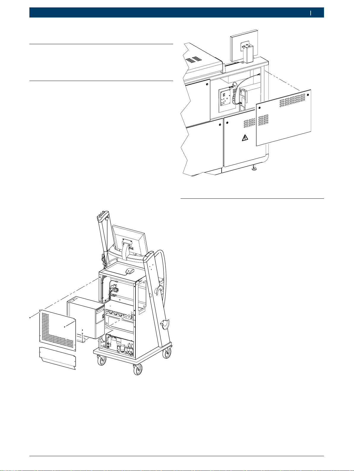
iDer PC wird standardmäßig bereits montiert und
angeschlossen in Produkten der RobertBoschGmbH
geliefert.
3.2 Umgebungsvoraussetzungen
3.2.1 Umgebung
¶PC vor Wasser oder Flüssigkeiten, hohen Temperatu-
ren und hoher Luftfeuchtigkeit schützen.
¶PC nicht in der Nähe von Produkten betreiben, die
starke Temperaturen oder elektromagnetische Felder
erzeugen.
¶Belüftungsöffnungen im Gehäuse stets freihalten.
¶PC auf eine stabile, saubere Oberfläche stellen und
nichts auf die Verbindungsleitungen des PC stellen.
3.2.2 Spannungsversorgung
¶Sicherstellen, dass die Versorgungsspannung mit der
Spannungsangabe des PC übereinstimmt.
¶Sicherstellen, dass der drei-adrige Schutzkontaktste-
cker des Netzteils an einer Schutzkontaktsteckdose
angeschlossen ist.
¶Falls der PC über ein Verlängerungskabel angeschlos-
sen wird, sicherstellen, dass die Gesamtstromstärke
aller an dieses Verlängerungskabel angeschlossenen
Geräte die zulässige Stromstärke für das Verlänge-
rungskabel und der vorgeschalteten Sicherung im
Sicherungskasten nicht überschreitet.

1 689 989 347 2018-02-08|Robert Bosch GmbH
1 687 023 850 – 858 | 5 de
3.3 Typen
Die Verwendung der unterschiedlichen Typen des PC ist
in nachstehender Tabelle dargestellt.
BEA 810
BEA 840
BEA 850
BEA 950
BEA UK
EPS 708
FSA 740
FSA 760
Bestellnummer
– – – – – – x x 1 687 023 850
x x x x x x – – 1 687 023 851
x x x x x x x x 1 687 023 858
3.4 Lieferumfang
Benennung Bestellnummer
PC -
Recovery-DVD 1 687 005 132
Betriebsanleitung<) 1 689 989 347
<) nur 1 687 023 858
3.5 Sonderzubehör
Benennung Bestellnummer
USB-Seriell-Umsetzer 1 684 465 508
3.6 Bedienelemente
4
5
6
7
459989-01_Pal
1
23
8
Fig. 1: Vorderansicht
1 DVD-Laufwerk
2 LED DVD-Laufwerk
3 Auswurftaste
4 Mikrofonanschluss
5 Kopfhöreranschluss
6 USB-Anschluss (USB3.0)
7 LED Festplattenzugriff
8 Ein-/Aus-Schalter mit intergrierter LED für Status Ein/Aus
Voraussetzung ist, dass PC auf der Rückseite eingeschaltet ist.
459989-02_Pal
12
Fig. 2: Rückansicht
1 Ein-/Aus-Schalter
2 Netzanschluss
LED-Status
LED Anzeige Status
Ein/Aus aus PC nicht betriebsbereit
leuchtet grün PC betriebsbereit
Festplattenzugriff aus Festplatte nicht aktiv
blinkt orange Daten werden gelesen
oder gespeichert
DVD-Laufwerk aus DVD-Laufwerk nicht aktiv
blinkt grün Daten werden gelesen
oder gebrannt
3.7 Anschlüsse
3.7.1 Aufteilung
Die Rückseite des PC ist in vier Bereiche gegliedert.
459989-03_Pal
Fig. 3: Anschlüsse
1 Netzteil
2 Lüfter
3 Mainboard
4 Schnittstellenkarten

1 689 989 347 2018-02-08| Robert Bosch GmbH
6 | 1 687 023 850 – 858de
3.7.2 Mainboard
459989-04_Pal
Fig. 4: Anschlüsse Mainboard
1 Maus (PS/2)
2 Monitor (VGA)
3 Monitor (Digital-Port)
4 LAN (RJ45)
5 Audio (Eingang)
6 Audio (Ausgang)
7 Mikrofon
8 USB (USB2.0)
9 USB (USB3.0)
10 Monitor (HDMI)
11 Monitor (DVI)
12 Tastatur (PS2)
LED-Status Netzwerk (LAN)
1
459989-05_Pal
2
Fig. 5: LED-Status Netzwerk (LAN)
1 LED Netzwerkzugriff
2 LED Netzwerk-Übertragungsrate
LED Anzeige Status
Netzwerk-
zugriff aus keine Verbindung
blinkt grün Daten werden übertragen
Netzwerk-
Übertra-
gungsrate
aus Übertragungsrate 10Mb/s
leuchtet grün Übertragungsrate 100Mb/s
leuchtet orange Übertragungsrate 1000Mb/s
3.7.3 Schnittstellenkarten
iPeripheriegeräte, die am PC betrieben werden, müs-
sen mindestens USB2.0 unterstützen. Der PC ist mit
sechs USB-Schnittstellen USB3.0 ausgerüstet; an
diesen USB-Schnittstellen können nur Peripheriege-
räte betrieben werden, welche USB3.0 unterstützen.
1
2
459989-06_Pal
Fig. 6: Anschlüsse
1 USB (USB2.0)
2 Seriell COM1/COM2

1 689 989 347 2018-02-08|Robert Bosch GmbH
1 687 023 850 – 858 | 7 de
4. Erstinbetriebnahme
4.1 Auspacken
1. PC auspacken.
2. Lieferumfang prüfen.
3. Verpackungsmaterialien fachgerecht entsorgen.
4.2 Aufstellen und Anschließen
iDer PC wird in den meisten Produkten der Ro-
bertRobertGmbH bereits montiert und angeschlos-
sen. Falls Sie einen PC bei der Erstinbetriebnahme
montieren müssen oder einen vorhandenen PC
durch einen Ersatzteil-PC ersetzen, gehen Sie wie
nachstehend beschrieben vor, ansonsten können Sie
dieses Kapitel überspringen.
1. PC von Spannung trennen.
2. Abdeckungen demontieren.
3. Verbindungsleitungen von bisherigem PC trennen.
4. Bisherigen PC demontieren.
5. Neuen PC montieren.
6. Verbindungsleitungen an neuen PC anschließen.
7. Abdeckungen montieren.
459989-07_Pal
Fig. 7: Einbaulage Tower im Fahrwagen
iWeitere Informationen zum Einbau im Prüfstand sie-
he Montageanleitung "EPS708" (1689978559).
458989-08_Pal
Fig. 8: Einbaulage Tower im Prüfstand
4.3 Software-Installation
4.3.1 Betriebssystem
iDas Betriebssystem WIN10 ist vorinstalliert. Für die
Aktivierung der Windows-Lizenz ist einmalig eine
aktive Internetverbindung erforderlich.
Wird die Windows-Lizenz nicht aktiviert sind manche
Windows-Funktionen nicht oder nur eingeschränkt
verfügbar
1. Produkt mit Spannung versorgen.
2. Steckerleiste einschalten.
3. Ein-/Aus-Schalter auf der Rückseite des PC einschalten.
4. PC über Standby-Taste einschalten.
Betriebssystem startet.
Spracheinstellungen werden angezeigt.
5. Landessprache wählen.
iOptional können, nach Auswahl der Landessprache,
weitere Einstellungen wie z.B. Appsprache, Tastatur-
layout oder Zeitzone angepasst werden.
6. Bildschirmhinweise beachten und befolgen.
PC ist betriebsbereit.
4.3.2 Software
Die Software (z.B. BEA-PC, FSA, ESI[tronic], EPS) wird
mit dem Produkt mitgeliefert. Ist die Software nicht
vorinstalliert, muss diese mithilfe des im Produkt beilie-
genden Datenträgers installiert werden.

1 689 989 347 2018-02-08| Robert Bosch GmbH
8 | 1 687 023 850 – 858de
5. Bedienung
5.1 Einschalten / Ausschalten
5.1.1 Einschalten
iIn nachfolgenden Fällen muss eine Wartezeit von bis
zu drei Minuten eingehalten werden:
$Zwischen Ausschalten und Einschalten des PC
über die Steckdosenleiste (nicht empfohlen).
$Zwischen Ausschalten und Einschalten über den
Ein-/Aus-Schalter (Rückseite des PCs).
iDie Wartezeit wird verkürzt, wenn zum Ein- und
Ausschalten die Ein-/Aus-Taste auf der Vorderseite
verwendet wird.
1. Produkt mit Spannung versorgen.
Steckdosenleiste am Fahrwagen einschalten oder PC
direkt mit Spannung versorgen.
2. PC über Ein-/Aus-Schalter auf der Rückseite ein-
schalten.
Betriebssystem startet.
iAnschließend kann der Rechner über die Ein-/Aus-
Taste an der Vorderseite des PCs ausgeschaltet und
eingeschaltet werden.
5.1.2 Ausschalten
1. Alle Programme beenden.
2. "Start >> Herunterfahren" wählen.
Betriebssystem fährt herunter.
PC schaltet selbstständig ab.
iAlternativ kann der Rechner über die Ein-/Aus-Taste
an der Vorderseite des PCs ausgeschaltet und einge-
schaltet werden.
5.2 Hinweis bei Störungen
iWenden Sie sich an Ihren Kundendienst, wenn Sie
die Störung mit nachstehenden Abhilfen nicht behe-
ben können.
5.2.1 Anzeige
Störung Abhilfe
Keine Anzeige. Der Monitor
bleibt dunkel. Sicherstellen, dass der PC und
alle weiteren Komponenten mit
Spannung versorgt sind.
Sicherstellen, dass die Steckdo-
senleiste am Fahrwagen einge-
schaltet ist.
Keine Anzeige. Der Monitor
bleibt dunkel, obwohl der
PC eingeschaltet ist.
Sicherstellen, dass alle Verbin-
dungsleitungen und die Netzan-
schlussleitung am Monitor ange-
schlossen sind.
Einstellungen (Helligkeit, Kont-
rast, Ausrichtung etc.) des Moni-
tors prüfen.
5.2.2 Eingabe
Störung Abhilfe
Eingabe über die Tasta-
tur funktioniert nicht. Sicherstellen, dass die Tastatur kor-
rekt am PC angeschlossen ist.
Verklemmungen von Tasten lösen und
Tastatur säubern oder tauschen, falls
Flüssigkeit in die Tastatur eingedrungen
ist und die Störung dauerhaft auftritt.
Eingabe über die Maus
funktioniert nicht. Sicherstellen, dass die Maus korrekt
am PC angeschlossen ist.
5.2.3 Wiedergabe
Störung Abhilfe
Ton wird nicht wieder-
gegeben. Bei integrierten Lautsprechern im Mo-
nitor sicherstellen, dass der Audioein-
gang des Monitors am Audioausgang
des PC angeschlossen ist.
Sicherstellen, dass der Ton in den Sys-
temeinstellungen eingeschaltet ist.
Daten von CD/DVD
werden nicht wiederge-
geben.
Sicherstellen, dass die CD/DVD sau-
ber ist, keine groben Beschädigun-
gen (Kratzer o.ä.) aufweist und mit
der richtigen Seite im Laufwerk einge-
legt ist.

1 689 989 347 2018-02-08|Robert Bosch GmbH
1 687 023 850 – 858 | 9 de
5.2.4 Anwendung
iFühren Sie nachstehende Maßnahmen in dieser Rei-
henfolge durch, wenn die Anwendung oder der PC
nicht mehr reagiert. Wenden Sie sich an Ihren Kun-
dendienst, wenn die Maßnahmen nicht weiterhelfen.
Windows Task Manager
1. <Strg>+<Umsch>+<Esc> drücken.
"Windows Task Manager" wird angezeigt.
2. Anwendung wählen, welche nicht reagiert.
3. <End Task> wählen.
Gewählte Anwendung wird beendet.
Ausschalten erzwingen
1. Ein-/Aus-Taste an der Vorderseite des PCs länger als
3 Sekunden drücken.
Betriebssystem fährt herunter.
2. Ein-/Aus-Schalter an der Vorderseite des PCs drü-
cken.
Betriebssystem startet.
6. Instandhaltung
!Alle Arbeiten an elektrischen Einrichtungen dürfen
nur Personen mit ausreichenden Kenntnissen und
Erfahrungen in der Elektrik durchführen.
6.1 Reinigung
!Keine scheuernden Reinigungsmittel und keine gro-
ben Werkstattputzlappen verwenden.
¶Das Gehäuse nur mit weichen Tüchern und neutralen
Reinigungsmitteln säubern.
6.2 Wartung
iFür den PC ist keine spezielle Wartung erforderlich.
Halten Sie den PC von Verschmutzungen frei.
6.3 Recovery-Prozess
!Alle Daten und Programme auf der Festplatte werden
während des Recovery-Prozesses gelöscht.
iAlle Tastatureingaben erfolgen, unabhängig von der
angeschlossenen Tastatur, auf Basis einer QWERTY-
Tastatur. Länderspezifische Abweichungen müssen
beachtet werden.
1. PC einschalten.
2. Recovery-DVD einlegen.
3. Während des Startvorgangs <F8> drücken.
4. Passwort "ia4kd" eingeben, um den Boot-Manager
aufzurufen.
Boot-Manager wird angezeigt.
5. Im Boot-Manager die Option "UEFI: ...DVDRAM..."
wählen.
6. Wahl mit Ebestätigen.
7. Beliebige Taste drücken, um von Recovery-DVD zu
starten.
Kommandozeile öffnet sich.

1 689 989 347 2018-02-08| Robert Bosch GmbH
10 | 1 687 023 850 – 858de
Eingabe Funktion
Yes Recovery starten
No Recovery-Prozess abbrechen und PC heruntefahren
iEingaben in der Kommandozeile erfolgen unabhän-
gig von der angeschlossenen Tastatur in englischem
Tastaturlayout.
8. "Yes" eingeben.
9. Eingabe mit Ebestätigen.
Recovery startet.
10. Bildschirmhinweise beachten und befolgen.
iNach erfolgreicher Recovery fährt der PC herunter.
Beim nächsten Start beginnt der Erstinbetriebnah-
me-Prozess des Betriebssystems (siehe Kap. 4.3.1).
6.4 Ersatz- und Verschleißteile
!Öffnen Sie den PC nicht selbsständig. Informieren
Sie Ihren Kundendienst, wenn Sie dauerhafte Störun-
gen haben. Es gibt Ersatzteile, die der Kundendienst
tauschen kann. Weiterhin kann der komplette PC er-
setzt werden – die Bestellnummern der Ersatz- und
Tausch-PCs sind nachstehend aufgeführt.
Serie Ersatzteil Tauschteil (BX)
1 687 023 850 1 687 023 858 1 682 666 413
1 687 023 851
7. Technische Daten
7.1 Maße und Gewichte
Eigenschaft Wert/Bereich
Abmessungen (H x B x T) Tower 370 x 175 x 385 mm
14.57 x 6.89 x 15.16 inch
Gewicht 6,4 kg
14.1 lb
7.2 Temperatur und Luftfeuchtigkeit
Eigenschaft Wert/Bereich
Lagertemperatur -25 °C – 60 °C
-13 °F – 140 °F
Betriebstemperatur 5 °C – 40 °C
41 °F – 104 °F
Relative Betriebsluftfeuchtigkeit 80 % (36 °C)
80 % (96.8 °F)
7.3 Leistungsangaben
Eigenschaft Wert/Bereich
Eingangsfrequenz 50 — 60 Hz
Eingangsspannung 115/240 V AC +/- 10 %
7.4 Hardware-Spezifikationen
Eigenschaft Wert/Bereich
Prozessor Intel Pentium G4560, 3,5 GHz
Arbeitsspeicher 8 GB DDR4, 2666 MHz
Festplatte 256 GB SSD

1 689 989 347 2018-02-08|Robert Bosch GmbH
1 687 023 850 – 858 | 11 en
en – Contents
1. Symbols used 11
1.1 In the documentation 11
1.1.1 Warning notices -
Structure and meaning 11
1.1.2 Symbols in this documentation 11
1.2 On the product 11
2. User information 12
2.1 Important notes 12
2.2 Safety instructions 12
2.3 Disposal 12
3. Product description 12
3.1 Intended use 12
3.2 Operating environment 12
3.2.1 Ambient conditions 12
3.2.2 Voltage supply 12
3.3 Types 13
3.4 Scope of delivery 13
3.5 Special accessories 13
3.6 Control elements 13
3.7 Ports 13
3.7.1 Layout 13
3.7.2 Motherboard 14
3.7.3 Interface cards 14
4. Initial commissioning 15
4.1 Unpacking 15
4.2 Installation and connection 15
4.3 Software installation 15
4.3.1 Operating system 15
4.3.2 Software 15
5. Operation 16
5.1 Switching on/off 16
5.1.1 switching on 16
5.1.2 Switching off 16
5.2 Instructions in case of faults 16
5.2.1 Display 16
5.2.2 Enter 16
5.2.3 Reproduction 16
5.2.4 Use 17
6. Maintenance 17
6.1 Ultrasonic cleaning 17
6.2 Preventive maintenance 17
6.3 Recovery process 17
6.4 Spare and wearing parts 18
7. Technical Data 18
7.1 Dimensions and weights 18
7.2 Temperature and humidity 18
7.3 Specifications 18
7.4 Hardware specifications 18
1. Symbols used
1.1 In the documentation
1.1.1 Warning notices -
Structure and meaning
Warning notices warn of dangers to the user or people
in the vicinity. Warning notices also indicate the con-
sequences of the hazard as well as preventive action.
Warning notices have the following structure:
Warning
symbol KEY WORD – Nature and source of hazard!
Consequences of hazard in the event of failu-
re to observe action and information given.
¶Hazard prevention action and information.
The key word indicates the likelihood of occurrence and
the severity of the hazard in the event of non-observan-
ce:
Key word Probability of
occurrence
Severity of danger if inst-
ructions not observed
DANGER Immediate impen-
ding danger Death or severe injury
WARNING Possible impending
danger Death or severe injury
CAUTION Possible dangerous
situation Minor injury
1.1.2 Symbols in this documentation
Symbol Designation Explanation
!Attention Warns about possible property damage.
iInformation Practical hints and other
useful information.
1.
2. Multi-step
operation Instruction consisting of several steps.
eOne-step
operation Instruction consisting of one step.
Intermediate
result An instruction produces a visible inter-
mediate result.
"Final result There is a visible final result on com-
pletion of the instruction.
1.2 On the product
!Observe all warning notices on products and ensure
they remain legible.

1 689 989 347 2018-02-08| Robert Bosch GmbH
12 | 1 687 023 850 – 858en
2. User information
2.1 Important notes
Important information on copyright, liability and warran-
ty provisions, as well as on equipment users and com-
pany obligations, can be found in the separate manual
"Important notes on and safety instructions for Bosch
Test Equipment". These instructions must be carefully
studied prior to start-up, connection and operation of
the 1 687 023 850 – 858 and must always be heeded.
2.2 Safety instructions
All the pertinent safety instructions can be found in the
separate manual "Important notes on and safety inst-
ructions for Bosch Test Equipment". These instructions
must be carefully studied prior to start-up, connection
and operation of the 1 687 023 850 – 858 and must
always be heeded.
2.3 Disposal
This 1 687 023 850 – 858 is subject to Euro-
pean guidelines 2012/19/EU (WEEE).
Old electrical and electronic devices, including-
cables and accessories or batteries must be
disposed of separate to household waste.
¶Please use the return and collection sys-
tems in place for disposal in your area.
¶Damage to the environment and hazards to
personal health are prevented by properly
disposing of 1 687 023 850 – 858.
3. Product description
3.1 Intended use
The PC is intended for use in conjunction with products
from RobertBoschGmbH (e.g. BEA, FSA, EPS). Any
other or additional application, e.g.in conjunction with
non-approved non-Bosch products, does not constitute
the intended use. The operator of the system is liable
for any damage resulting from such usage and not Ro-
bertBoschGmbH.
iAs standard, the PC is already installed and connec-
ted in RobertBoschGmbH products on delivery.
3.2 Operating environment
3.2.1 Ambient conditions
¶The PC is to be protected against water and other
moisture, high temperatures and high humidity.
¶Never operate the PC in the vicinity of products
which generate high temperatures or electromagne-
tic fields.
¶Make sure the vent openings in the housing are not
obstructed.
¶Position the PC on a stable, clean surface and do not
stand anything on the PC connecting cables.
3.2.2 Voltage supply
¶Make sure the power supply corresponds to the
voltage indicated on the PC.
¶Make sure the three-wire grounding-type connector
of the power supply unit is connected to a grounding
outlet.
¶If the PC is connected by way of an extension cable,
make sure the total current level of all the devices
connected to this extension cable does not exceed
the permissible current level for the extension cable
and the fuse in the fuse box.

1 689 989 347 2018-02-08|Robert Bosch GmbH
1 687 023 850 – 858 | 13 en
3.3 Types
Use of the various types of PC is shown in the table
below.
BEA810
BEA840
BEA850
BEA950
BEA UK
EPS708
FSA740
FSA760
Part number
– – – – – – x x 1 687 023 850
x x x x x x – – 1 687 023 851
x x x x x x x x 1 687 023 858
3.4 Scope of delivery
Designation Part number
PC -
Recovery DVD 1 687 005 132
Operating instructions<) 1 689 989 347
<) only 1 687 023 858
3.5 Special accessories
Designation Part number
USB serial converter 1 684 465 508
3.6 Control elements
4
5
6
7
459989-01_Pal
1
23
8
Fig. 1: Front view
1 DVD drive
2 DVD drive LED
3 Eject button
4 Microphone connection
5 Headphone port
6 USB connection (USB3.0)
7 Hard disk access LED
8 On/off switch with integral LED for on/off status
Prerequisite is that PC is switched on at the back.
459989-02_Pal
12
Fig. 2: Rear view
1 On/Off switch
2 Mains port
LED status
LED Display Status
On/Off off PC not ready for operation
lights up green PC ready for operation
Hard disk access off Hard disk not active
flashes orange Data being read or saved
DVD drive off DVD drive not active
Flashing green Data being read or written
3.7 Ports
3.7.1 Layout
The back of the PC is divided into four sections.
459989-03_Pal
Fig. 3: Ports
1 Power supply unit
2 Fan
3 Motherboard
4 Interface cards

1 689 989 347 2018-02-08| Robert Bosch GmbH
14 | 1 687 023 850 – 858en
3.7.2 Motherboard
459989-04_Pal
Fig. 4: Mainboard connections
1 Mouse (PS/2)
2 Monitor (VGA)
3 Monitor (digital port)
4 LAN (RJ45)
5 Audio (input)
6 Audio (output)
7 Microphone
8 USB (USB2.0)
9 USB (USB3.0)
10 Monitor (HDMI)
11 Monitor (DVI)
12 Keyboard (PS/2)
Network LED status (LAN)
1
459989-05_Pal
2
Fig. 5: Network LED status (LAN)
1 Network access LED
2 Network transmission rate LED
LED Display Status
Network
access off No link
Flashing green Data being transmitted
Network
transmissi-
on rate
off Transmission rate 10Mb/s
lights up green Transmission rate 100Mb/s
lights up orange Transmission rate 1000Mb/s
3.7.3 Interface cards
iPeripheral devices operated with the PC must sup-
port at least USB2.0. The PC is provided with six
USB interfaces USB3.0; these USB interfaces can
only be used for the operation of peripheral devices
which support USB3.0.
1
2
459989-06_Pal
Fig. 6: Ports
1 USB (USB2.0)
2 Serial COM1/COM2

1 689 989 347 2018-02-08|Robert Bosch GmbH
1 687 023 850 – 858 | 15 en
4. Initial commissioning
4.1 Unpacking
1. Unpack the PC.
2. Check the scope of delivery.
3. Dispose of the packaging materials in the proper
manner.
4.2 Installation and connection
iThe PC is supplied already installed and connected
in most RobertRobertGmbH products. Proceed
as described below if a PC has to be installed on
commissioning or if an existing PC is to be replaced.
Otherwise this Section can be ignored.
1. Disconnect the PC from the power supply.
2. Remove the covers.
3. Disconnect the connecting cables from the previous
PC.
4. Remove the previous PC.
5. Fit the new PC.
6. Connect the connecting cables to the new PC.
7. Fit the covers.
459989-07_Pal
Fig. 7: Installation position of tower in trolley
iFor further information on installation in the
tester, see the fitting instructions "EPS708"
(1689978559).
458989-08_Pal
Fig. 8: Installation position of tower in tester
4.3 Software installation
4.3.1 Operating system
iThe WIN10 operating system is factory-installed. An
active internet connection is required for the durati-
on of a one-time Windows license activation.
If the Windows license is not activated, some Win-
dows functions will be unavailable or restricted.
1. Supply the product with power.
2. Switch on the multi-point connector.
3. Switch on the On/Off switch on the back of the PC.
4. Switch on the PC by way of the Standby button.
The operating system starts up.
The language settings are displayed.
5. Select the local language.
iOptionally, after the national language has been
selected, additional settings such as apps language,
keyboard layout or time zone can be set.
6. Read and follow the instructions on the screen.
The PC is ready for operation.
4.3.2 Software
The software (e.g. BEA-PC, FSA, ESI[tronic], EPS) is
supplied with the product. If the software is not pre-
installed, it must be installed using the data carrier pro-
vided with the product.

1 689 989 347 2018-02-08| Robert Bosch GmbH
16 | 1 687 023 850 – 858en
5. Operation
5.1 Switching on/off
5.1.1 switching on
iAlways allow a waiting time of up to three minutes in
the following situations:
$Between switching the PC off and on at the multi-
ple socket outlet (not recommended).
$Between switch-off and switch-on using the ON/
OFF switch at the PC power supply unit (back of
PC).
iThe wait time is shortened if the power key on the
front is used for switching on and off.
1. Supply the product with power.
Switch on the multiple socket outlet on the trolley or
connect the PC directly to the power supply.
2. Switch on the PC via the on/off switch on the back
of the PC.
The operating system starts up.
iThe computer can then be switched off and on via
the power key on the front of the PC.
5.1.2 Switching off
1. End all programs.
2. Select "Start >> Shutdown".
The operating system shuts down.
The PC switches off automatically.
iAlternatively, the computer can be switched off and
on via the power key on the front of the PC.
5.2 Instructions in case of faults
iContact Customer Service if any problem cannot be
rectified employing the remedies listed below.
5.2.1 Display
Fault Remedy
No display. The monitor re-
mains blank. Make sure the PC and all other
components are being supplied
with power.
Make sure the multiple socket
outlet at the trolley has been
switched on.
No display. The monitor re-
mains blank although the PC
is switched on.
Make sure all connecting cables
and the power cord are connec-
ted to the monitor.
Check the monitor settings
(brightness, contrast, alignment
etc.).
5.2.2 Enter
Fault Remedy
Keypad input not func-
tioning. Make sure the keypad is properly con-
nected to the PC.
Release any sticking keys and clean the
keypad or replace following the ingress
of liquid and in the case of persistent
problems.
Mouse input not func-
tioning. Make sure the mouse is properly con-
nected to the PC.
5.2.3 Reproduction
Fault Remedy
No sound reproduc-
tion. If the monitor has integrated louds-
peakers, make sure the monitor audio
input is connected to the audio output
of the PC.
Make sure the sound function has be-
en activated in the system settings.
No reproduction of da-
ta from CD/DVD. Make sure the CD/DVD is clean, exhi-
bits no major damage (scratches etc.)
and is inserted the right way round in
the drive.

1 689 989 347 2018-02-08|Robert Bosch GmbH
1 687 023 850 – 858 | 17 en
5.2.4 Use
iTake the action described below in the given se-
quence if the application or PC no longer reacts.
Contact Customer Service if this action does not
help.
Windows task manager
1. Press <Ctrl>+<Shift>+<Esc>.
"Windows Task Manager" is displayed.
2. Select the application which is not reacting.
3. Select <End Task>.
The selected application is terminated.
Forced switch-off
1. Press the power key on the front of the PC for more
than three seconds.
The operating system shuts down.
2. Press the power key on the front of the PC.
The operating system starts up.
6. Maintenance
!Work on electrical equipment is only to be per-
formed by persons with sufficient knowledge and
experience of electrical systems.
6.1 Ultrasonic cleaning
!Do not use abrasive cleaning agents and coarse
workshop cloths.
¶The housing is only to be cleaned with a soft cloth
and neutral cleaning agents.
6.2 Preventive maintenance
iThe PC does not require any special maintenance
work. Keep the PC clean.
6.3 Recovery process
!All data and programs on the hard disk will be
erased during the recovery process.
iAll keyboard input, regardless of the keyboard con-
nected, is based on a QWERTY keyboard layout. Note
any country-specific variations that may apply.
1. Switch on the PC/laptop.
2. Insert the recovery DVD.
3. Press <F8> during the startup process.
4. Enter the password "ia4kd" to open the Boot Ma-
nager.
The Boot Manager is displayed.
5. In the Boot Manager, select the option "UEFI: ...DV-
DRAM..." .
6. Confirm selection with E.
7. Press any key to start from the Recovery DVD.
The command line opens.

1 689 989 347 2018-02-08| Robert Bosch GmbH
18 | 1 687 023 850 – 858en
Enter Function
Yes Start recovery
No Cancel the recovery process and shut down the PC
iEntries in the command line are based on an English
keyboard layout regardless of the keyboard connec-
ted.
8. Enter "Yes".
9. Confirm entry with E.
The recovery will commence.
10. Read and follow the instructions on the screen.
iAfter a successful recovery, the PC shuts down. The
next time the computer starts, the initial commissi-
oning process for the operating system begins (see
sec. 4.3.1).
6.4 Spare and wearing parts
!The PC should never be opened by the user. Inform
Customer Service in the event of persistent pro-
blems. Spare parts are available for replacement
by Customer Service. The entire PC can also be
replaced – the order numbers for replacement and
exchange PCs are listed below.
Series Spare Part Exchange part (BX)
1 687 023 850 1 687 023 858 1 682 666 413
1 687 023 851
7. Technical Data
7.1 Dimensions and weights
Property Value / range
Dimensions (H x W x D) Tower 370 x 175 x 385 mm
14.57 x 6.89 x 15.16 inch
Weight 6,4 kg
14.1 lb
7.2 Temperature and humidity
Property Value / range
Storage Temperature -25 °C – 60 °C
-13 °F – 140 °F
Operating Temperature 5 °C – 40 °C
41 °F – 104 °F
Relative operating humidity 80 % (36 °C)
80 % (96.8 °F)
7.3 Specifications
Property Value / range
Frequency 50 — 60 Hz
Input voltage 115/240 V AC +/- 10 %
7.4 Hardware specifications
Property Value / range
Processor Intel Pentium G4560, 3,5 GHz
Main-memory capa-
city 8 GB DDR4, 2666 MHz
Hard disk 256 GB SSD

1 689 989 347 2018-02-08|Robert Bosch GmbH
1 687 023 850 – 858 | 19 bg
bg – Съдържание
1. Използвани символи 19
1.1 В документацията 19
1.1.1 Предупредителни указания –
формат изначение 19
1.1.2 Символи – наименование и значение19
1.2 Върху продукта 19
2. Указания за потребителя 20
2.1 Важни указания 20
2.2 Указания за безопасност 20
2.3 Изхвърляне на отпадъци 20
3. Описание на продукта 20
3.1 Употреба по предназначение 20
3.2 Задължителни условия на околната среда 20
3.2.1 Околна среда 20
3.2.2 Електрозахранване 20
3.3 Типове 21
3.4 Обем на доставката 21
3.5 Специални принадлежности 21
3.6 Елементи за управление 21
3.7 Връзки 21
3.7.1 Разпределение 21
3.7.2 Дънна платка 22
3.7.3 Карти за интерфейси 22
4. Първоначално пускане в експлоатация 23
4.1 Разопаковане 23
4.2 Поставяне и свързване 23
4.3 Инсталация на софтуера 23
4.3.1 Операционна система 23
4.3.2 Софтуер 23
5. Обслужване 24
5.1 Включване/изключване 24
5.1.1 Включване 24
5.1.2 Изключване 24
5.2 Указания при неизправности 24
5.2.1 Индикация 24
5.2.2 Въвеждане 24
5.2.3 Възпроизвеждане 24
5.2.4 Приложение 25
6. Поддържане в изправно състояние 25
6.1 Почистване 25
6.2 Поддръжка 25
6.3 Процес Recovery 25
6.4 Резервни и износващи се части 26
7. Технически данни 26
7.1 Размери и тегло 26
7.2 Температура и влажност на въздуха 26
7.3 Данни за мощността 26
7.4 Спецификации на хардуера 26
1. Използвани символи
1.1 В документацията
1.1.1 Предупредителни указания –
формат изначение
Предупредителните указания предупреждават за
опасности за потребителя и намиращите се наблизо
хора. Освен това предупредителните указания описват
последствията от опасността и мерките, с които могат да
се избегнат. Предупредителните указания се състоят от:
Предупре
дителен
символ
СИГНАЛНА ДУМА – Вид и източник на
опасността!
Последствия от опасността в случай
на неспазване на посочените мерки и
указания.
¶Мерки и указания с цел избягване на
опасността.
Сигналната дума указва вероятността за възникване,
както и степента на риска при неспазване:
Сигнална дума Вероятност за
настъпване
Сериозност на
опасността
при неспазване
ОПАСНОСТ Непосредствено
грозяща опасност Смърт или тежко
телесно нараняване
ПРЕДУ-
ПРЕЖДЕНИЕ Евентуално грозяща
опасност Смърт или тежко
телесно нараняване
ВНИМАНИЕ Евентуална опасна
ситуация Леко телесно
нараняване
1.1.2 Символи – наименование и значение
Сим-
вол
Наимено-
вание
Значение
!Внимание Предупреждава за възможни
материални щети.
iИнформация Указания за употреба и друга
полезна информация.
1.
2. Многостъп-
ково действие Изискване за действие, включващо
няколко стъпки
eЕдностъпково
действие Изискване за действие, включващо
една стъпка.
Междинен
резултат По време на изискването за действие
се вижда междинен резултат.
"Краен
резултат В края на изискването за действие се
вижда крайният резултат.
1.2 Върху продукта
!Спазвайте всички предупредителни знаци върху
продуктите и ги поддържайте в четлив вид!

1 689 989 347 2018-02-08| Robert Bosch GmbH
20 | 1 687 023 850 – 858bg
2. Указания за потребителя
2.1 Важни указания
Важни указания за споразумението за авторското
право, отговорността и гаранцията, за групата
потребители и за задълженията на предприятието ще
намерите в отделната инструкция "Важни указания
иуказания за безопасност за Bosch Test Equipment".
Те трябва да се прочетат внимателно и да се спазват
задължително преди пускане в експлоатация,
свързване и работа с 1 687 023 850 – 858.
2.2 Указания за безопасност
Всички указания за безопасност ще намерите
вотделната инструкция "Важни указания и указания
за безопасност Bosch Test Equipment". Те трябва
да се прочетат внимателно и задължително да се
спазват преди пускане в експлоатация, свързване
иработа с1 687 023 850 – 858.
2.3 Изхвърляне на отпадъци
1 687 023 850 – 858 подлежи на
европейската директива 2012/19/ЕО (ОЕЕО
– Директива за отпадъци от електрическо и
електронно оборудване).
Излезлите от употреба електрически
иелектронни уреди, включително кабели
ипринадлежности, както и акумулатори
ибатерии трябва да се изхвърлят разделно
от битовите отпадъци.
¶За изхвърлянето използвайте
съществуващите системи за връщане
исъбиране.
¶С правилното изхвърляне на
1 687 023 850 – 858 избягвате
замърсяване на околната среда и
увреждане на здравето на хората.
3. Описание на продукта
3.1 Употреба по предназначение
Компютърът е предназначен за работа в комбинация
с продуктите на RobertBoschGmbH (напр. BEA,
FSA, EPS). Друга употреба или употреба извън
посочените граници, напр. в комбинация с
неодобрени чужди продукти, се счита за употреба
не по предназначение. RobertBoschGmbH не
поема отговорност за произтичащите от това
щети, а отговорността се поема от потребителя на
инсталацията.
iВ стандартния случай компютърът се доставя
монтиран в и свързан с продуктите на Ro-
bertBoschGmbH.
3.2 Задължителни условия на околната
среда
3.2.1 Околна среда
¶Предпазвайте компютъра от вода или течности,
високи температури и висока влажност на въздуха.
¶Не използвайте компютъра в близост до продукти,
които генерират високи температури или силни
електромагнитни полета.
¶Винаги дръжте свободни отворите за проветрение
в корпуса.
¶Поставете компютъра върху стабилна и чиста
повърхност и не поставяйте нищо върху
свързващите кабели на компютъра.
3.2.2 Електрозахранване
¶Уверете се, че захранващото напрежение
съответства на посоченото напрежение на
компютъра.
¶Уверете се, че трижилният щепсел със защитен
контакт на мрежовото захранване е свързан в
контакт със защитен проводник.
¶Ако компютърът се свързва чрез удължител,
се уверете, че общата сила на тока на всички
устройства, свързани към този удължител,
не надвишава допустимата сила на тока на
удължителя и предварително свързания
предпазител в кутията с предпазители.
This manual suits for next models
4
Table of contents
Languages:
Other Bosch Desktop manuals

Bosch
Bosch PC2018 User manual

Bosch
Bosch Rexroth VSB 40.1 Technical manual

Bosch
Bosch 1 687 023 689 User manual

Bosch
Bosch Professional GTD 1 User manual

Bosch
Bosch 1 687 023 850 User manual

Bosch
Bosch DCU 220 User manual

Bosch
Bosch 1 687 023 575 User manual

Bosch
Bosch BEA 810 User manual

Bosch
Bosch Kiox User manual

Bosch
Bosch Rexroth 3 842 998 350 User manual
Popular Desktop manuals by other brands

Compaq
Compaq Compaq dx2390 Microtower Hardware reference guide

Dell
Dell POWEREDGETM MVT01 Getting started guide

Protech Systems
Protech Systems BPC-8960 Quick reference guide

Honeywell
Honeywell DPS 6 PLUS Operation

Allmand
Allmand MAXI-LITE ML EX V-Series Operator's manual

Shuttle
Shuttle XPC slim user guide