1 689 989 158 2012-10-12| Robert Bosch GmbH
6 | 1 687 023 652 – 658de
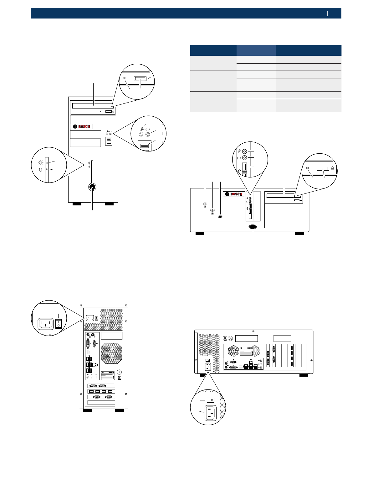
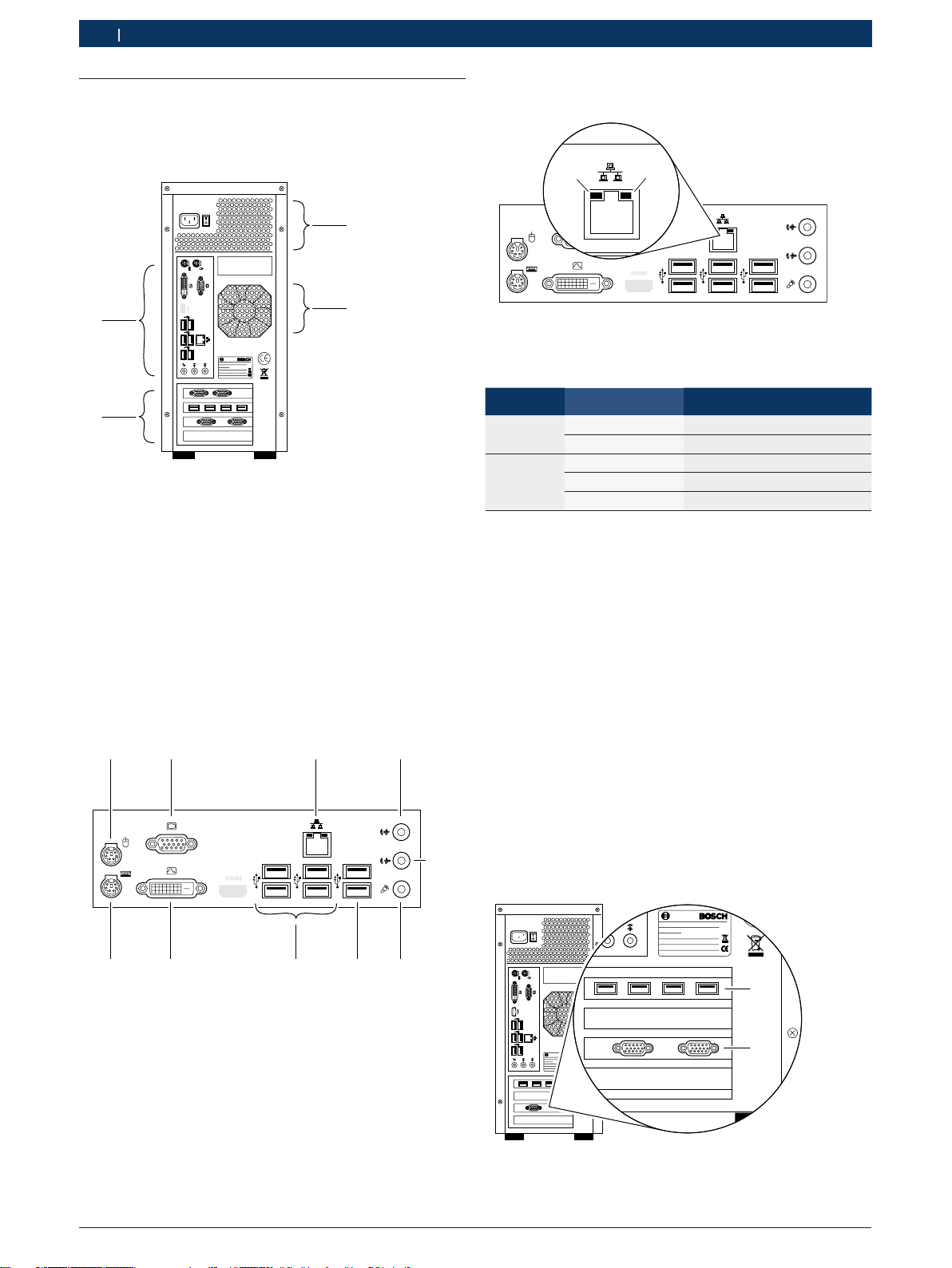
3. Produktbeschreibung
3.1 Bestimmungsgemäße Verwendung
Der PC ist für den Betrieb in Verbindung mit Produk-
ten der Robert Bosch GmbH (z. B. BEA, FSA, EPS)
vorgesehen. Eine andere oder darüber hinausgehende
Benutzung, z. B. in Verbindung mit nicht freigegebenen
Fremdprodukten, gilt als nicht bestimmungsgemäß.
Für hieraus resultierende Schäden haftet nicht die Ro-
bert Bosch GmbH, sondern der Betreiber der Anlage.
iDer PC wird standardmäßig bereits montiert und
angeschlossen in Produkten der Robert Bosch GmbH
geliefert.
3.2 Umgebungsvoraussetzungen
3.2.1 Umgebung
¶PC vor Wasser oder Flüssigkeiten, hohen Temperatu-
ren und hoher Luftfeuchtigkeit schützen.
¶PC nicht in der Nähe von Produkten betreiben, die
starke Temperaturen oder elektromagnetische Felder
erzeugen.
¶Belüftungsöffnungen im Gehäuse stets freihalten.
¶PC auf eine stabile, saubere Oberfläche stellen und
nichts auf die Verbindungsleitungen des PC stellen.
3.2.2 Spannungsversorgung
¶Sicherstellen, dass die Versorgungsspannung mit der
Spannungsangabe des PCs übereinstimmt.
¶Sicherstellen, dass der drei-adrige Schutzkontakt-
stecker des Netzteils an einer geerdeten Steckdose
angeschlossen ist.
¶Falls der PC über ein Verlängerungskabel angeschlos-
sen wird, sicherstellen, dass die Gesamtstromstärke
aller an dieses Verlängerungskabel angeschlossenen
Geräte die zulässige Stromstärke für das Verlänge-
rungskabel und der vorgeschalteten Sicherung im
Sicherungskasten nicht überschreitet.
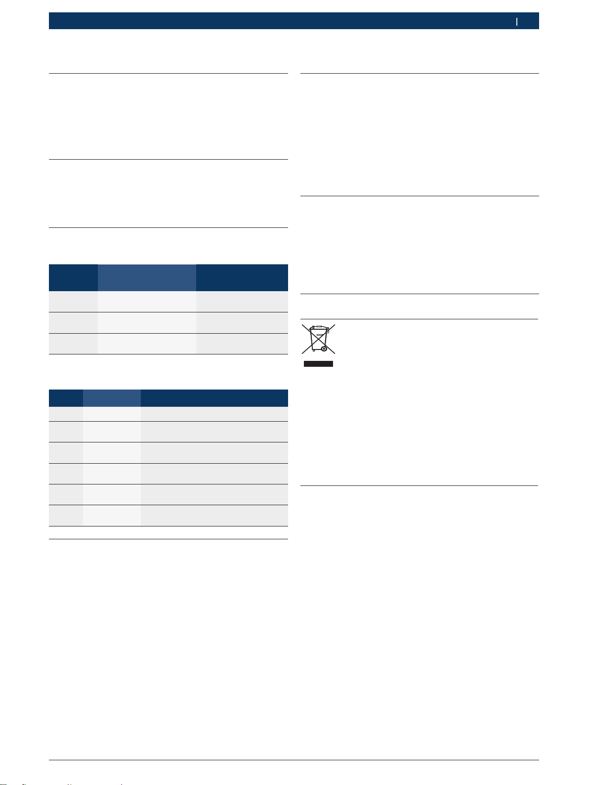
3.3 Typen
Die Verwendung der unterschiedlichen Typen des PC ist
in nachstehender Tabelle dargestellt.
BEA 810
BEA 840
BEA 850
BEA 950
BEA UK
EPS 708
EPS 815
FSA 740
FSA 760
Bestellnummer
Tower
Desktop
– – – – – – – x x 1 687 023 652 x –
x x x x – x – – – 1 687 023 653 x –
– – – – x – – – – 1 687 023 654 x –
– – – – – – x – – 1 687 023 655 – x
3.4 Lieferumfang
3.4.1 1 687 023 652
Benennung Bestellnummer
PC 1 687 023 652
Recovery-DVD 1 687 005 092
Betriebsanleitung 1 689 989 158
3.4.2 1 687 023 653
Benennung Bestellnummer
PC 1 687 023 653
Recovery-DVD 1 687 005 092
Betriebsanleitung 1 689 989 158
3.4.3 1 687 023 654
Benennung Bestellnummer
PC 1 687 023 654
Recovery-DVD 1 687 005 092
Betriebsanleitung 1 689 989 158
3.4.4 1 687 023 655
Benennung Bestellnummer
PC 1 687 023 655
Netzanschlussleitung 1 684 461 119
Recovery-DVD 1 687 005 092
CD "EP-Software" 1 687 000 956
Betriebsanleitung 1 689 989 158
3.5 Sonderzubehör
Benennung Bestellnummer
USB-Seriell-Umsetzer 1 684 465 508