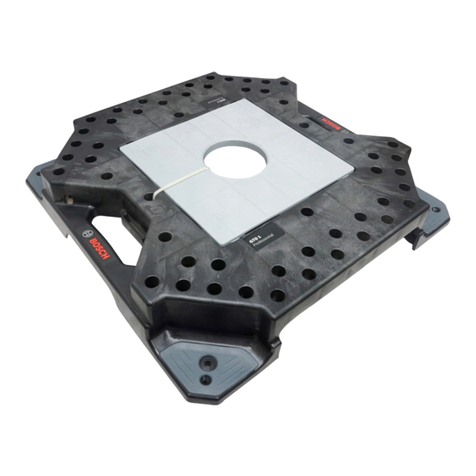
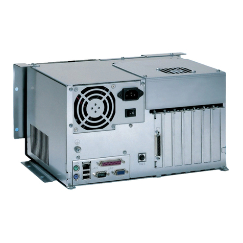
Bosch 1 687 023 689 User manual

1 687 023 689 – 692
de
Betriebsanleitung
PC (Personal Computer)
en
Operating instructions
PC (Personal Computer)
fr
Consignes d‘utilisation
PC (Personal Computer)
es
Instrucciones de Funcionamiento
PC (Ordenador personal)
it
Istruzioni d‘uso
PC (Personal Computer)
sv
Bruksanvisning
PC (Persondator)
nl
Bedieningshandleiding
PC (Personal Computer)
pt
Instruções de funcionamento
PC (Personal Computer)
fi
Käyttöohjeet
PC (Personal Computer)
da
Driftsinstruktioner
PC (Personal Computer)
no
Driftsanvisning
PC (Personal Computer)
pl
Instrukcje obsługi
PC (Komputer osobisty)
cs
Návod k použití
PC (Personal Computer)
tr
Çalıştırma talimatları
PC (Kişisel bilgisayar)
zh
操作指南
PC (计算机)


1 689 989 190 2018-02-24|Robert Bosch GmbH
1 687 023 689 – 692 | 3 de
Inhaltsverzeichnis Deutsch 4
Contents English 13
Sommaire français 22
Índice español 31
Indice italiano 40
Innehållsförteckning svenska 49
Inhoud Nederlands 58
Índice português 67
Sisällysluettelo Suomi 76
Indholdsfortegnelse Dansk 85
Innholdsfortegnelse norsk 94
Spis treści po polsku 103
Obsah česky 112
İçindekiler Türkçe 121
内容目录 中文 130

1 689 989 190 2018-02-24| Robert Bosch GmbH
4 | 1 687 023 689 – 692de
Inhaltsverzeichnis Deutsch
1. Verwendete Symbolik 2
1.1 In der Dokumentation 2
1.1.1 Warnhinweise – Aufbau und Bedeutung 2
1.1.2 Symbole – Benennung und Bedeutung 2
1.2 Auf dem Produkt 2
2. Benutzerhinweise 2
2.1 Wichtige Hinweise 2
2.2 Sicherheitshinweise 2
2.3 Entsorgung 2
2.4 Elektromagnetische Verträglichkeit (EMV) 2
3. Produktbeschreibung 3
3.1 Bestimmungsgemäße Verwendung 3
3.2 Umgebungsvoraussetzungen 3
3.2.1 Umgebung 3
3.2.2 Spannungsversorgung 3
3.3 Typen 3
3.4 Lieferumfang 3
3.4.1 1 687 023 689 3
3.4.2 1 687 023 690 3
3.4.3 1 687 023 691 3
3.4.4 1 687 023 692 3
3.5 Sonderzubehör 3
3.6 Bedienelemente 4
3.6.1 Tower 4
3.6.2 Desktop 4
3.7 Anschlüsse 5
3.7.1 Aufteilung 5
3.7.2 Mainboard 5
3.7.3 Schnittstellenkarten 5
4. Erstinbetriebnahme 6
4.1 Auspacken 6
4.2 Aufstellen und Anschließen 6
4.2.1 Tower 6
4.2.2 Desktop 7
4.3 Softwareinstallation 7
4.3.1 Betriebssystem 7
4.3.2 Software 7
4.3.3 doPDF 7
5. Bedienung 8
5.1 Einschalten / Ausschalten 8
5.1.1 Einschalten 8
5.1.2 Ausschalten 8
5.2 Hinweis bei Störungen 8
5.2.1 Anzeige 8
5.2.2 Eingabe 8
5.2.3 Wiedergabe 8
5.2.4 Anwendung 8
6. Instandhaltung 9
6.1 Reinigung 9
6.2 Wartung 9
6.3 Ersatz- und Verschleißteile 9
7. Technische Daten 9
7.1 Maße und Gewichte 9
7.2 Temperatur und Luftfeuchtigkeit 9
7.3 Leistungsangaben 9

1 689 989 190 2018-02-24|Robert Bosch GmbH
1 687 023 689 – 692 | 5 de
1. Verwendete Symbolik
1.1 In der Dokumentation
1.1.1 Warnhinweise – Aufbau und Bedeutung
Warnhinweise warnen Benutzer oder umstehende Perso-
nen vor Gefahren. Zusätzlich beschreiben Warnhinweise
die Folgen der Gefahr und die Maßnahmen zur Vermei-
dung. Warnhinweise haben folgenden Aufbau:
Warn-
symbol
SIGNALWORT – Art und Quelle der Gefahr!
Folgen der Gefahr bei Missachtung der aufge-
führten Maßnahmen und Hinweise.
¶Maßnahmen und Hinweise zur Vermeidung
der Gefahr.
Das Signalwort zeigt die Eintrittswahrscheinlichkeit sowie
die Schwere der Gefahr bei Missachtung:
Signalwort Eintrittswahrschein-
lichkeit
Schwere der Gefahr bei
Missachtung
GEFAHR Unmittelbar drohende
Gefahr
Tod oder schwere Körper-
verletzung
WARNUNG Mögliche drohende
Gefahr
Tod oder schwere Körper-
verletzung
VORSICHT Mögliche gefährliche
Situation
Leichte Körperverletzung
1.1.2 Symbole – Benennung und Bedeutung
Symbol Benennung Bedeutung
!Achtung Warnt vor möglichen Sachschäden.
iInformation Anwendungshinweise und andere nütz-
liche Informationen.
1.
2.
Mehrschrittige
Handlung
Aus mehreren Schritten bestehende
Handlungsaufforderung.
eEinschrittige
Handlung
Aus einem Schritt bestehende Hand-
lungsaufforderung.
Zwischener-
gebnis
Innerhalb einer Handlungsaufforderung
wird ein Zwischenergebnis sichtbar.
"Endergebnis Am Ende einer Handlungsaufforderung
wird das Endergebnis sichtbar.
1.2 Auf dem Produkt
!Die auf den Produkten dargestellten Warnzeichen
beachten und in lesbarem Zustand halten.
2. Benutzerhinweise
2.1 Wichtige Hinweise
Wichtige Hinweise zur Vereinbarung über Urheberrecht,
Haftung und Gewährleistung, über die Benutzergruppe
und über die Verpflichtung des Unternehmens finden
Sie in der separaten Anleitung "Wichtige Hinweise und
Sicherheitshinweise zu Bosch Test Equipment".
Diese sind vor Inbetriebnahme, Anschluss und Bedie-
nung von 1 687 023 689 – 692 sorgfältig durchzulesen
und zwingend zu beachten.
2.2 Sicherheitshinweise
Alle Sicherheitshinweise finden Sie in der separaten
Anleitung "Wichtige Hinweise und Sicherheitshinweise
zu Bosch Test Equipment". Diese sind vor Inbetriebnah-
me, Anschluss und Bedienung von 1 687 023 689 – 692
sorgfältig durchzulesen und zwingend zu beachten.
2.3 Entsorgung
1 687 023 689 – 692 unterliegt der europäi-
schen Richtlinie 2012/19/EU (WEEE).
Elektro- und Elektronik-Altgeräte einschließ-
lich Leitungen und Zubehör sowie Akku und
Batterien müssen getrennt vom Hausmüll
entsorgt werden.
¶Nutzen Sie zur Entsorgung die zur Verfü-
gung stehenden Rückgabesysteme und
Sammelsysteme.
¶Mit der ordnungsgemäßen Entsorgung
von 1 687 023 689 – 692 vermeiden Sie
Umweltschäden und eine Gefährdung der
persönlichen Gesundheit.
2.4 Elektromagnetische Verträglichkeit (EMV)
1 687 023 689 – 692 erfüllt die Kriterien nach EMV-
Richtlinie 2014/30/EU, EN 55032.
Warnhinweis: Der Betrieb dieses Geräts bzw. dieser
Einrichtung kann im Wohnbereich Funkstörungen verur-
sachen.

1 689 989 190 2018-02-24| Robert Bosch GmbH
6 | 1 687 023 689 – 692de
3. Produktbeschreibung
3.1 Bestimmungsgemäße Verwendung
Der PC ist für den Betrieb in Verbindung mit Produk-
ten der RobertBoschGmbH (z.B. BEA, FSA, EPS)
vorgesehen. Eine andere oder darüber hinausgehende
Benutzung, z.B. in Verbindung mit nicht frei gegebenen
Fremdprodukten, gilt als nicht bestimmungsgemäß.
Für hieraus resultierende Schäden haftet nicht die Ro-
bertBoschGmbH, sondern der Betreiber der Anlage.
iDer PC wird standardmäßig bereits montiert und an-
geschlossen in Produkten der RobertBoschGmbH
geliefert.
3.2 Umgebungsvoraussetzungen
3.2.1 Umgebung
¶PC vor Wasser oder Flüssigkeiten, hohen Temperatu-
ren und hoher Luftfeuchtigkeit schützen.
¶PC nicht in der Nähe von Produkten betreiben, die
starke Temperaturen oder elektromagnetische Fel-
der erzeugen.
¶Belüftungsöffnungen im Gehäuse stets frei halten.
¶PC auf eine stabile, saubere Oberfläche stellen und
nichts auf die Verbindungsleitungen des PC stellen.
3.2.2 Spannungsversorgung
¶Sicherstellen, dass die Versorgungsspannung mit der
Spannungsangabe des PCs übereinstimmt.
¶Sicherstellen, dass der drei-adrige Schutzkontakt-
stecker des Netzteils an einer geerdeten Steckdose
angeschlossen ist.
¶Falls der PC über ein Verlängerungskabel ange-
schlossen wird, sicherstellen, dass die Gesamt-
stromstärke aller an dieses Verlängerungskabel
angeschlossenen Geräte die zulässige Stromstärke
für das Verlängerungskabel und der vorgeschalteten
Sicherung im Sicherungskasten nicht überschreitet.
3.3 Typen
Die Verwendung der unterschiedlichen Typen des PC ist
in nachstehender Tabelle dargestellt.
BEA 810
BEA 840
BEA 850
BEA 950
BEA UK
EPS 708
EPS 815
FSA 740
FSA 760
Bestellnummer
Tower
Desktop
– – – – – – – x x 1 687 023 689 x –
x x x x – x – – – 1 687 023 690 x –
– – – – x – – – – 1 687 023 691 x –
– – – – – – x – – 1 687 023 692 – x
3.4 Lieferumfang
3.4.1 1 687 023 689
Benennung Bestellnummer
PC 1 687 023 689
Recovery-DVD 1 687 005 096
Betriebsanleitung 1 689 989 190
3.4.2 1 687 023 690
Benennung Bestellnummer
PC 1 687 023 690
Recovery-DVD 1 687 005 096
Betriebsanleitung 1 689 989 190
3.4.3 1 687 023 691
Benennung Bestellnummer
PC 1 687 023 691
Recovery-DVD 1 687 005 096
Betriebsanleitung 1 689 989 190
3.4.4 1 687 023 692
Benennung Bestellnummer
PC 1 687 023 692
Netzanschlussleitung 1 684 461 119
Recovery-DVD 1 687 005 133
CD "EP-Software" 1 687 000 956
Betriebsanleitung 1 689 989 190
3.5 Sonderzubehör
Benennung Bestellnummer
USB-seriell-Umsetzer 1 684 465 508

1 689 989 190 2018-02-24|Robert Bosch GmbH
1 687 023 689 – 692 | 7 de
3.6 Bedienelemente
3.6.1 Tower
459935-01_Ht
1
23
4
5
6
7
8
9
Abb. 1: Vorderansicht
1 DVD-Laufwerk
2 LED DVD-Laufwerk
3 Auswurftaste
4 Mikrofonanschluss
5 Kopfhöreranschluss
6 USB-Anschluss (USB2.0)
7 LED Ein/Aus
8 LED Festplattenzugriff
9 Standby-Taste
459935-02_Ht
12
Abb. 2: Rückansicht
1 Netzanschluss
2 Ein-/Aus-Schalter
LED-Status
LED Anzeige Status
Ein/Aus aus PC nicht betriebsbereit
leuchtet grün PC betriebsbereit
Festplattenzugriff aus Festplatte nicht aktiv
blinkt grün Daten werden gelesen
oder gespeichert
DVD-Laufwerk aus DVD-Laufwerk nicht aktiv
blinkt grün Daten werden gelesen
oder gebrannt
3.6.2 Desktop
459935-03_Ht
123
4
5
6
8 9
10
7
Abb. 3: Vorderansicht
1 LED Festplattenzugriff
2 LED Ein/Aus
3 Reset-Taste
4 Mikrofonanschluss
5 Kopfhöreranschluss
6 USB (USB2.0)
7 DVD-Laufwerk
8 LED DVD-Laufwerk
9 Auswurftaste
10 Standby-Taste
459935-04_Ht
1
2
Abb. 4: Rückansicht
1 Ein-/Aus-Schalter
2 Netzanschluss

1 689 989 190 2018-02-24| Robert Bosch GmbH
8 | 1 687 023 689 – 692de
3.7 Anschlüsse
3.7.1 Aufteilung
Die Rückseite des PC ist in vier Bereiche gegliedert.
459935-13_Ht
1
2
3
4
Abb. 5: Anschlüsse
1 Netzteil
2 Lüfter
3 Mainboard
4 Schnittstellenkarten
iDie Anschlüsse des Mainboards sind bei jedem Typ
des PC gleich ausgelegt (sieheKap.3.7.2). Die An-
schlüsse im Bereich der Schnittstellenkarten ist vom
Typ des PC abhängig (sieheKap.3.7.3).
3.7.2 Mainboard
1
459935-05_Ht
234
5
6
7
89
10
Abb. 6: Anschlüsse Mainboard
1 Maus (PS/2)
2 Monitor (VGA)
3 LAN (RJ45)
4 Audio (Eingang)
5 Audio (Ausgang)
6 Mikrofon
7 USB (USB3.0)
8 USB (USB2.0)
9 Monitor (DVI)
10 Tastatur (PS/2)
LED-Status Netzwerk (LAN)
1
459935-06_Ht
2
Abb. 7: LED-Status Netzwerk (LAN)
1 LED Netzwerkzugriff
2 LED Netzwerk-Übertragungsrate
LED Anzeige Status
Netzwerk-
zugriff
aus keine Verbindung
blinkt grün Daten werden übertragen
Netzwerk-
Übertra-
gungsrate
aus Übertragungsrate 10Mb/s
leuchtet grün Übertragungsrate 100Mb/s
leuchtet orange Übertragungsrate 1000Mb/s
3.7.3 Schnittstellenkarten
iPeripheriegeräte, die am PC betrieben werden, müs-
sen mindestens USB2.0 unterstützen. Der PC ist mit
zwei USB-Schnittstellen USB3.0 ausgerüstet; an die-
sen USB-Schnittstellen können nur Peripheriegeräte
betrieben werden, welche USB3.0 unterstützen.
Wenn Sie CAN-, SVTW- oder VPM844ISO-Module
verwenden, bauen Sie diese vor der Montage des PC
im Fahrwagen oder Prüfstand ein. Weitere Infor-
mationen siehe Montageanleitung "1687001949"
(1689978556).
!An SVTW-Modulen dürfen am 25-poligen Anschluss
ausschließlich Geräte mit Brandschutzgehäuse be-
trieben werden.
1 687 023 689 / 1 687 023 690
459935-07_Ht
1
2
Abb. 8: Anschlüsse 1 687 023 689 / 1 687 023 690
1 USB (USB2.0)
2 Seriell COM1/COM2

1 689 989 190 2018-02-24|Robert Bosch GmbH
1 687 023 689 – 692 | 9 de
1 687 023 691
459935-08_Ht
1
2
3
Abb. 9: Anschlüsse 1 687 023 691
1 Seriell COM1/COM3
2 USB (USB2.0)
3 Seriell COM2/COM4
1 687 023 692
459935-09_Ht
123
Abb. 10: Anschlüsse 1 687 023 692
1 Seriell COM1/COM3
2 Seriell COM2/COM4
3 USB (USB2.0)
4. Erstinbetriebnahme
4.1 Auspacken
1. PC auspacken.
2. Lieferumfang prüfen.
3. Verpackungsmaterialien fachgerecht entsorgen.
4.2 Aufstellen und Anschließen
iDer PC wird in den meisten Produkten der Ro-
bertRobertGmbH bereits montiert und angeschlos-
sen. Falls Sie einen PC bei der Erstinbetriebnahme
montieren müssen oder einen vorhandenen PC
durch einen Ersatzteil-PC ersetzen, gehen Sie wie
nachstehend beschrieben vor, ansonsten können Sie
dieses Kapitel überspringen.
1. PC von Spannung trennen.
2. Abdeckungen demontieren.
3. Verbindungsleitungen von altem PC trennen.
4. Alten PC demontieren.
5. Neuen PC montieren.
6. Verbindungsleitungen an neuen PC anschließen.
7. Abdeckungen montieren.
4.2.1 Tower
459935-10_H
t
Abb. 11: Einbaulage Tower im Fahrwagen

1 689 989 190 2018-02-24| Robert Bosch GmbH
10 | 1 687 023 689 – 692de
iWeitere Informationen zum Einbau im Prüfstand sie-
he Montageanleitung "EPS708" (1689978559).
459935-12_Ht
Abb. 12: Einbaulage Tower im Prüfstand
4.2.2 Desktop
iWeitere Informationen zum Einbau siehe Betriebsan-
leitung "KMA802/822".
459935-11_Ht
Abb. 13: Einbaulage Desktop
(links: im Fahrwagen, rechts: im Prüfstand)
4.3 Softwareinstallation
4.3.1 Betriebssystem
!Auf dem Desktop finden Sie die "END-USER LICEN-
SE AGREEMENT (EULA) FOR MICROSOFT SOFT-
WARE" (EULA.XPS). Bitte beachten Sie die dort
enthaltenen Hinweise.
iDas Betriebssystem WIN7 ist vorinstalliert.
1. Produkt mit Spannung versorgen.
2. Steckerleiste einschalten.
3. Ein-/Aus-Schalter auf der Rückseite des PC einschal-
ten.
4. PC über Standby-Taste einschalten.
Betriebssystem startet.
Spracheinstellungen werden angezeigt.
5. Landessprache wählen.
6. Bildschirmhinweise beachten und befolgen.
PC ist betriebsbereit.
4.3.2 Software
Die Software (z.B. BEA-PC, FSA, ESI[tronic], EPS) wird
mit dem Produkt mitgeliefert. Ist die Software nicht
vorinstalliert, muss diese mithilfe des im Produkt beilie-
genden Datenträgers installiert werden.
4.3.3 doPDF
Wenn Probleme beim Drucken auftreten (z.B. bei HP-
Druckern in Verbindung mit ESA), können Sie das Pro-
gramm "doPDF" aus nachstehendem Verzeichnis
'C:\BOSCH_PR\DOPDF\DOPDF-7.EXE' installieren und
als Standard-Drucker einrichten.

1 689 989 190 2018-02-24|Robert Bosch GmbH
1 687 023 689 – 692 | 11 de
5. Bedienung
5.1 Einschalten / Ausschalten
5.1.1 Einschalten
iIn nachfolgenden Fällen muss eine Wartezeit von bis
zu drei Minuten eingehalten werden:
$Zwischen Ausschalten und Einschalten des PC
über die Steckdosenleiste.
$Zwischen Ausschalten und Einschalten über den
Ein-/Aus-Schalter am Netzteil des PC.
Die Wartezeit wird verkürzt, wenn die Standby-Taste
nach dem Einschalten gedrückt wird.
1. Produkt mit Spannung versorgen.
2. Steckdosenleiste am Fahrwagen einschalten oder PC
direkt mit Spannung versorgen.
3. Standby-Taste an der Vorderseite des PC drücken.
Betriebssystem startet.
5.1.2 Ausschalten
1. Alle Programme beenden.
2. "Start >> Herunterfahren" wählen.
Betriebssystem fährt herunter.
PC schaltet selbstständig ab.
5.2 Hinweis bei Störungen
iWenden Sie sich an Ihren Kundendienst, wenn Sie
die Störung mit nachstehenden Abhilfen nicht behe-
ben können.
5.2.1 Anzeige
Störung Abhilfe
Keine Anzeige. Der Monitor
bleibt dunkel.
Sicherstellen, dass der PC und
alle weiteren Komponenten mit
Spannung versorgt sind.
Sicherstellen, dass die Steckdo-
senleiste am Fahrwagen einge-
schaltet ist.
Keine Anzeige. Der Monitor
bleibt dunkel, obwohl der
PC eingeschaltet ist.
Sicherstellen, dass alle Verbin-
dungsleitungen und die Netzan-
schlussleitung am Monitor ange-
schlossen sind.
Einstellungen (Helligkeit, Kont-
rast, Ausrichtung etc.) des Moni-
tors prüfen.
5.2.2 Eingabe
Störung Abhilfe
Eingabe über die Tastatur
funktioniert nicht.
Sicherstellen, dass die Tastatur
korrekt am PC angeschlossen ist.
Verklemmungen von Tasten lösen
und Tastatur säubern oder tau-
schen, falls Flüssigkeit in die Tas-
tatur eingedrungen ist und die
Störung dauerhaft auftritt.
Eingabe über die Maus funk-
tioniert nicht.
Sicherstellen, dass die Maus kor-
rekt am PC angeschlossen ist.
5.2.3 Wiedergabe
Störung Abhilfe
Ton wird nicht wiederge-
geben.
Bei integrierten Lautsprechern
im Monitor sicherstellen, dass
der Audioeingang des Monitors
am Audioausgang des PC ange-
schlossen ist.
Sicherstellen, dass der Ton in
den Systemeinstellungen einge-
schaltet ist.
Daten von CD/DVD werden
nicht wiedergegeben.
Sicherstellen, dass die CD/DVD
sauber ist, keine groben Beschä-
digungen (Kratzer o.ä.) aufweist
und mit der richtigen Seite im
Laufwerk eingelegt ist.
5.2.4 Anwendung
iFühren Sie nachstehende Maßnahmen in dieser Rei-
henfolge durch, wenn die Anwendung oder der PC
nicht mehr reagiert. Wenden Sie sich an Ihren Kun-
dendienst, wenn die Maßnahmen nicht weiterhelfen.
Windows Task Manager
1. "Windows Task Manager" mit einer der nachstehen-
den Möglichkeiten starten.
$<Strg> + <Alt> + <Entf> drücken.
$<Strg> + <Umsch> + <Esc> drücken.
$Mit der rechten Maustaste auf die Taskleiste kli-
cken und im Kontextmenü "Start Task Manager"
wählen.
"Windows Task Manager" wird angezeigt.
2. Anwendung wählen, welche nicht reagiert.
3. <End Task> wählen.
Gewählte Anwendung wird beendet.
Restart
¶Reset-Taste an der Vorderseite des PC drücken.
Betriebssystem fährt herunter und startet neu.
Ausschalten erzwingen
1. Standby-Taste an der Vorderseite des PC länger als
drei Sekunden drücken.
Betriebssystem fährt herunter.
2. Standby-Taste an der Vorderseite des PC drücken.
Betriebssystem startet.

1 689 989 190 2018-02-24| Robert Bosch GmbH
12 | 1 687 023 689 – 692de
6. Instandhaltung
!Alle Arbeiten an elektrischen Einrichtungen dürfen
nur Personen mit ausreichenden Kenntnissen und
Erfahrungen in der Elektrik durchführen.
6.1 Reinigung
!Keine scheuernden Reinigungsmittel und keine gro-
ben Werkstattputzlappen verwenden.
¶Das Gehäuse nur mit weichen Tüchern und neutra-
len Reinigungsmitteln säubern.
6.2 Wartung
iFür den PC ist keine spezielle Wartung erforderlich.
Halten Sie den PC von Verschmutzungen frei.
6.3 Ersatz- und Verschleißteile
!Öffnen Sie den PC nicht selbstständig. Informieren
Sie Ihren Kundendienst, wenn Sie dauerhafte Stö-
rungen haben. Es gibt Ersatzteile, die der Kunden-
dienst tauschen kann. Weiterhin kann der komplette
PC ersetzt werden – die Bestellnummern der Ersatz-
und Tausch-PCs sind nachstehend aufgeführt.
Serie Ersatzteil Tauschteil
1 687 023 689 1 687 023 699 1 682 666 383
1 687 023 690
1 687 023 691 1 687 023 700 1 682 666 384
1 687 023 692 1 687 023 692 1 682 666 385
7. Technische Daten
7.1 Maße und Gewichte
Eigenschaft Wert/Bereich
Abmessungen (H x B x T) Tower 360 x 185 x 395 mm
14.17 x 7.28 x 15.55 inch
Abmessungen (H x B x T) Desktop 150 x 425 x 425 mm
5.91 x 16.73 x 16.73 inch
Gewicht 8 kg
17.64 lb
7.2 Temperatur und Luftfeuchtigkeit
Eigenschaft Wert/Bereich
Lagertemperatur -25 °C – 60 °C
-13 °F – 140 °F
Betriebstemperatur 5 °C – 40 °C
41 °F – 104 °F
Relative Betriebsluftfeuchtigkeit 80 % (36 °C)
80 % (96.8 °F)
7.3 Leistungsangaben
Eigenschaft Wert/Bereich
Eingangsfrequenz 50 — 60 Hz
Eingangsspannung 115/240 V AC +/- 10 %

1 689 989 190 2018-02-24|Robert Bosch GmbH
1 687 023 689 – 692 | 13 en
Contents English
1. Symbols used 14
1.1 In the documentation 14
1.1.1 Warning notices - Structure and
meaning 14
1.1.2 Symbols in this documentation 14
2. User information 14
2.1 Important notes 14
2.2 Safety instructions 14
2.3 Disposal 14
2.4 FCC compliance 14
3. Product description 15
3.1 Intended use 15
3.2 Operating environment 15
3.2.1 Ambient conditions 15
3.2.2 Power supply 15
3.3 Types 15
3.4 Scope of delivery 15
3.4.1 1 687 023 689 15
3.4.2 1 687 023 690 15
3.4.3 1 687 023 691 15
3.4.4 1 687 023 692 15
3.5 Special accessories 15
3.6 Design features 16
3.6.1 Tower 16
3.6.2 Desktop 16
3.7 Connections 17
3.7.1 Layout 17
3.7.2 Mainboard 17
3.7.3 Interface cards 17
4. Commissioning 18
4.1 Unpacking 18
4.2 Installation and connection 18
4.2.1 Tower 18
4.2.2 Desktop 19
4.3 Software installation 19
4.3.1 Operating system 19
4.3.2 Software 19
4.3.3 doPDF 19
5. Operation 20
5.1 Switch-on / switch-off 20
5.1.1 Switch-on 20
5.1.2 Switch-off 20
5.2 Faults 20
5.2.1 Display 20
5.2.2 Input 20
5.2.3 Reproduction 20
5.2.4 Application 20
6. Maintenance 21
6.1 Cleaning 21
6.2 Maintenance 21
6.3 Spare and wearing parts 21
7. Technical data 21
7.1 Dimensions and weights 21
7.2 Temperature and humidity 21
7.3 Specifications 21

1 689 989 190 2018-02-24| Robert Bosch GmbH
14 | 1 687 023 689 – 692en
1. Symbols used
1.1 In the documentation
1.1.1 Warning notices -
Structure and meaning
Warning notices warn of dangers to the user or people
in the vicinity. Warning notices also indicate the con-
sequences of the hazard as well as preventive action.
Warning notices have the following structure:
Warning
symbol
KEY WORD – Nature and source of hazard!
Consequences of hazard in the event of failu-
re to observe action and information given.
¶Hazard prevention action and information.
The key word indicates the likelihood of occurrence and
the severity of the hazard in the event of non-observan-
ce:
Key word Probability of
occurrence
Severity of danger if inst-
ructions not observed
DANGER Immediate impen-
ding danger
Death or severe injury
WARNING Possible impending
danger
Death or severe injury
CAUTION Possible dangerous
situation
Minor injury
1.1.2 Symbols in this documentation
Symbol Designation Explanation
!Attention Warns about possible property damage.
iInformation Practical hints and other
useful information.
1.
2.
Multi-step
operation
Instruction consisting of several steps.
eOne-step
operation
Instruction consisting of one step.
Intermediate
result
An instruction produces a visible inter-
mediate result.
"Final result There is a visible final result on com-
pletion of the instruction.
1.2 On the product
!Observe all warning notices on products and ensure
they remain legible.
2. User information
2.1 Important notes
Important information on copyright, liability and warran-
ty provisions, as well as on equipment users and com-
pany obligations, can be found in the separate manual
"Important notes on and safety instructions for Bosch
Test Equipment". These instructions must be carefully
studied prior to start-up, connection and operation of
the 1 687 023 689 – 692 and must always be heeded.
2.2 Safety instructions
All the pertinent safety instructions can be found in the
separate manual "Important notes on and safety inst-
ructions for Bosch Test Equipment". These instructions
must be carefully studied prior to start-up, connection
and operation of the 1 687 023 689 – 692 and must
always be heeded.
2.3 Disposal
This 1 687 023 689 – 692 is subject to Euro-
pean guidelines 2012/19/EU (WEEE).
Old electrical and electronic devices, including-
cables and accessories or batteries must be
disposed of separate to household waste.
¶Please use the return and collection sys-
tems in place for disposal in your area.
¶Damage to the environment and hazards to
personal health are prevented by properly
disposing of 1 687 023 689 – 692.
2.4 FCC compliance
The following statement applies to the products co-
vered in this manual, unless otherwise specified herein.
The statement for other products will appear in the ac-
companying documentation.
NOTE: This equipment has been tested and found to
comply with the limits for a Class B digital device, pur-
suant to Part 15 of the FCC Rules and meets all require-
ments of the Canadian Interference-Causing Equipment
Standard ICES-003 for digital apparatus. These limits
are designed to provide reasonable protection against
harmful interference in a residential installation.
This equipment generates, uses, and can radiate radio
frequency energy and, if not installed and used in
accordance with the instructions, may cause harmful in-
terference to radio communications. However, there is
no guarantee that interference will not occur in a parti-
cular installation. If this equipment does cause harmful
interference to radio or television reception, which can
be determined by turning the equipment off and on, the

1 689 989 190 2018-02-24|Robert Bosch GmbH
1 687 023 689 – 692 | 15 en
3. Product description
3.1 Intended use
The PC is intended for use in conjunction with products
from RobertBoschGmbH (e.g.BEA, FSA, EPS). Any
other or additional application, e.g.in conjunction with
non-approved non-Bosch products, does not constitute
the intended use. The operator of the system is liable
for any damage resulting from such usage and not Ro-
bertBoschGmbH.
iAs standard, the PC is already installed and connec-
ted in RobertBoschGmbH products on delivery.
3.2 Operating environment
3.2.1 Ambient conditions
¶The PC is to be protected against water and other
moisture, high temperatures and high humidity.
¶Never operate the PC in the vicinity of products
which generate high temperatures or electromagne-
tic fields.
¶Make sure the vent openings in the housing are not
obstructed.
¶Position the PC on a stable, clean surface and do
not stand anything on the PC connecting cables.
3.2.2 Power supply
¶Make sure the power supply corresponds to the
voltage indicated on the PC.
¶Make sure the three-wire grounding-type connector
of the power supply unit is connected to a grounded
socket.
¶If the PC is connected by way of an extension cable,
make sure the total current level of all the devices
connected to this extension cable does not exceed
the permissible current level for the extension cable
and the fuse in the fuse box.
3.3 Types
Use of the various types of PC is shown in the table
below.
BEA 810
BEA 840
BEA 850
BEA 950
BEA UK
EPS 708
EPS 815
FSA 740
FSA 760
Order number
Tower
Desktop
– – – – – – – x x 1 687 023 689 x –
x x x x – x – – – 1 687 023 690 x –
– – – – x – – – – 1 687 023 691 x –
– – – – – – x – – 1 687 023 692 – x
3.4 Scope of delivery
3.4.1 1 687 023 689
Designation Order number
PC 1 687 023 689
Recovery DVD 1 687 005 096
Operating instructions 1 689 989 190
3.4.2 1 687 023 690
Designation Order number
PC 1 687 023 690
Recovery DVD 1 687 005 096
Operating instructions 1 689 989 190
3.4.3 1 687 023 691
Designation Order number
PC 1 687 023 691
Recovery DVD 1 687 005 096
Operating instructions 1 689 989 190
3.4.4 1 687 023 692
Designation Order number
PC 1 687 023 692
Power cord 1 684 461 119
Recovery DVD 1 687 005 096
"EP software" CD 1 687 000 956
Operating instructions 1 689 989 190
3.5 Special accessories
Designation Order number
USB serial converter 1 684 465 508
user is encouraged to try to correct the interference by
one or more of the following measures:
RReorient or relocate the receiving antenna.
RIncrease the separation between the equipment and
receiver.
RConnect the equipment into an outlet on a circuit
different from that to which the receiver is connec-
ted.
Consult the dealer or an experienced radio/T.V. techni-
cian for help.

1 689 989 190 2018-02-24| Robert Bosch GmbH
16 | 1 687 023 689 – 692en
3.6 Design features
3.6.1 Tower
459935-01_Ht
1
23
4
5
6
7
8
9
Fig. 1: Front view
1 DVD drive
2 DVD drive LED
3 Eject button
4 Microphone connection
5 Headphone connection
6 USB connection (USB2.0)
7 On/Off LED
8 Hard disk access LED
9 Standby button
459935-02_Ht
12
Fig. 2: Rear view
1 Mains connection
2 On/Off switch
LED status
LED Display Status
On/Off Off PC not ready for operation
Green light PC ready for operation
Hard disk access Off Hard disk not active
Flashing green Data being read or saved
DVD drive Off DVD drive not active
Flashing green Data being read or written
3.6.2 Desktop
459935-03_Ht
123
4
5
6
8 9
10
7
Fig. 3: Front view
1 Hard disk access LED
2 On/Off LED
3 Reset button
4 Microphone connection
5 Headphone connection
6 USB (USB2.0)
7 DVD drive
8 DVD drive LED
9 Eject button
10 Standby button
459935-04_Ht
1
2
Fig. 4: Rear view
1 On/Off switch
2 Mains connection

1 689 989 190 2018-02-24|Robert Bosch GmbH
1 687 023 689 – 692 | 17 en
3.7 Connections
3.7.1 Layout
The back of the PC is divided into four sections.
459935-13_Ht
1
2
3
4
Fig. 5: Connections
1 Power supply unit
2 Fan
3 Mainboard
4 Interface cards
iThe design of the mainboard connections is the
same for every type of PC (refer toSec.3.7.2). The
connections in the area of the interface cards de-
pend on the type of PC (refer toSec.3.7.3).
3.7.2 Mainboard
1
459935-05_Ht
234
5
6
7
89
10
Fig. 6: Mainboard connections
1 Mouse (PS/2)
2 Monitor (VGA)
3 LAN (RJ45)
4 Audio (input)
5 Audio (output)
6 Microphone
7 USB (USB3.0)
8 USB (USB2.0)
9 Monitor (DVI)
10 Keypad (PS/2)
Network LED status (LAN)
1
459935-06_Ht
2
Fig. 7: Network LED status (LAN)
1 Network access LED
2 Network transmission rate LED
LED Display Status
Network
access
Off No link
Flashing green Data being transmitted
Network
transmissi-
on rate
Off Transmission rate 10Mb/s
Green light Transmission rate 100Mb/s
Orange light Transmission rate 1000Mb/s
3.7.3 Interface cards
iPeripheral devices operated with the PC must sup-
port at least USB2.0. The PC is provided with two
USB interfaces USB3.0; these USB interfaces can
only be used for the operation of peripheral devices
which support USB3.0. If use is to be made of CAN,
SVTW or VPM844ISO modules, these are to be
installed before fitting the PC in the trolley or tester.
For further information refer to the fitting instruc-
tions "1687001949" (1689978556).
!Only devices with a fire-proof housing are to be ope-
rated from the 25-pin connection of SVTW modules.
1 687 023 689 / 1 687 023 690
459935-07_Ht
1
2
Fig. 8: Connections 1 687 023 689 / 1 687 023 690
1 USB (USB2.0)
2 Serial COM1/COM2

1 689 989 190 2018-02-24| Robert Bosch GmbH
18 | 1 687 023 689 – 692en
1 687 023 691
459935-08_Ht
1
2
3
Fig. 9: Connections 1 687 023 691
1 Serial COM1/COM3
2 USB (USB2.0)
3 Serial COM2/COM4
1 687 023 692
459935-09_Ht
123
Fig. 10: Connections 1 687 023 692
1 Serial COM1/COM3
2 Serial COM2/COM4
3 USB (USB2.0)
4. Commissioning
4.1 Unpacking
1. Unpack the PC.
2. Check the scope of delivery.
3. Dispose of the packaging materials in the proper
manner.
4.2 Installation and connection
iThe PC is supplied already installed and connected
in most RobertRobertGmbH products. Proceed
as described below if a PC has to be installed on
commissioning or if an existing PC is to be replaced.
Otherwise this Section can be ignored.
1. Disconnect the PC from the power supply.
2. Remove the covers.
3. Disconnect the connecting cables from the old PC.
4. Remove the old PC.
5. Fit the new PC.
6. Connect the connecting cables to the new PC.
7. Fit the covers.
4.2.1 Tower
459935-10_H
t
Fig. 11: Installation position of tower in trolley

1 689 989 190 2018-02-24|Robert Bosch GmbH
1 687 023 689 – 692 | 19 en
iFor further information on installation in the tes-
ter refer to the fitting instructions "EPS708"
(1689978559).
459935-12_Ht
Fig. 12: Installation position of tower in test bench
4.2.2 Desktop
iFor further information on installation refer to the
operating instructions "KMA802/822".
459935-11_Ht
Fig. 13: Desktop installation position
(left: in trolley, right: in test bench)
4.3 Software installation
4.3.1 Operating system
!The "END-USER LICENSE AGREEMENT (EULA) FOR
MICROSOFT SOFTWARE" (EULA.XPS) can be found
on the desktop. Please heed the information contai-
ned in this.
iWIN7 is pre-installed as operating system.
1. Supply the product with power.
2. Switch on the multi-point connector.
3. Switch on the On/Off switch on the back of the PC.
4. Switch on the PC by way of the Standby button.
The operating system starts up.
The language settings are displayed.
5. Select the local language.
6. Heed and follow the instructions on the screen.
The PC is ready for operation.
4.3.2 Software
The software (e.g.BEA-PC, FSA, ESI[tronic], EPS) is
supplied with the product. If the software is not pre-
installed, it must be installed using the data carrier pro-
vided with the product.
4.3.3 doPDF
If printing problems are encountered (e.g. on
HP printers in conjunction with ESA), the program
"doPDF" can be installed from the directory
'C:\BOSCH_PR\DOPDF\DOPDF-7.EXE' and set up as
standard printer.

1 689 989 190 2018-02-24| Robert Bosch GmbH
20 | 1 687 023 689 – 692en
5. Operation
5.1 Switch-on / switch-off
5.1.1 Switch-on
iAlways allow a waiting time of up to three minutes in
the following situations:
$Between switching the PC off and on at the mul-
tiple socket outlet.
$Between switch-off and switch-on using the ON/
OFF switch at the PC power supply unit.
Pressing the Standby button after switch-on shortens
the waiting time.
1. Supply the product with power.
2. Switch on the multiple socket outlet on the trolley or
connect the PC directly to the power supply.
3. Press the Standby button on the front of the PC.
The operating system starts up.
5.1.2 Switch-off
1. End all programs.
2. Select "Start >> Shutdown".
The operating system shuts down.
The PC switches off automatically.
5.2 Faults
iContact Customer Service if any problem cannot be
rectified employing the remedies listed below.
5.2.1 Display
Fault Remedy
No display. The monitor re-
mains blank.
Make sure the PC and all other
components are being supplied
with power.
Make sure the multiple socket
outlet at the trolley has been
switched on.
No display. The monitor re-
mains blank although the PC
is switched on.
Make sure all connecting cables
and the power cord are connec-
ted to the monitor.
Check the monitor settings
(brightness, contrast, alignment
etc.).
5.2.2 Input
Fault Remedy
Keypad input not functio-
ning.
Make sure the keypad is properly
connected to the PC.
Release any sticking keys and
clean the keypad or replace fol-
lowing the ingress of liquid and
in the case of persistent prob-
lems.
Mouse input not functio-
ning.
Make sure the mouse is properly
connected to the PC.
5.2.3 Reproduction
Fault Remedy
No sound reproduction. If the monitor has integrated
loudspeakers, make sure the mo-
nitor audio input is connected to
the audio output of the PC.
Make sure the sound function
has been activated in the system
settings.
No reproduction of data
from CD/DVD.
Make sure the CD/DVD is clean,
exhibits no major damage (scrat-
ches etc.) and is inserted the
right way round in the drive.
5.2.4 Application
iTake the action described below in the given se-
quence if the application or PC no longer reacts.
Contact Customer Service if this action does not
help.
Windows task manager
1. Employ one of the following options to start the
"Windows Task Manager".
$Press <Ctrl> + <Alt> + <Del>.
$Press <Ctrl> + <Shift> + <Esc>.
$Click onto the task bar with the right mouse key
and select "Start Task Manager" in the context
menu.
"Windows Task Manager" is displayed.
2. Select the application which is not reacting.
3. Select <End Task>.
The selected application is terminated.
Restart
¶Press the Reset button on the front of the PC.
The operating system shuts down and starts up
again.
Forced switch-off
1. Press the Standby button on the front of the PC for
more than three seconds.
The operating system shuts down.
2. Press the Standby button on the front of the PC.
The operating system starts up.
This manual suits for next models
4
Table of contents
Languages:
Other Bosch Desktop manuals

Bosch
Bosch BEA 810 User manual

Bosch
Bosch DCU 130 User manual

Bosch
Bosch Rexroth VSB 40.1 Technical manual

Bosch
Bosch GTA 60 W Professional User manual

Bosch
Bosch Purion 200 User manual

Bosch
Bosch 1 687 023 575 User manual

Bosch
Bosch PC2018 User manual

Bosch
Bosch Professional GTD 1 User manual

Bosch
Bosch DCU 220 User manual

Bosch
Bosch 1 687 023 850 Series User manual