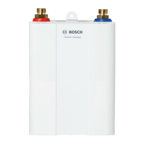
Bosch HI4000P User manual

6721851963 (2023/01) div
de Infrarot-Heizgerät Installationsanleitung . . . . . . . . . . . . . . . . . . . . . . . . . . . . . . . . . . . . . . . . . . . . . . . . . . . . 2
en Infrared panel IInstallation instructions . . . . . . . . . . . . . . . . . . . . . . . . . . . . . . . . . . . . . . . . . . . . . . . . . 10
es Panel infrarrojo Manual de instalación . . . . . . . . . . . . . . . . . . . . . . . . . . . . . . . . . . . . . . . . . . . . . . . . . . . 18
fr Panneau infrarouge Notice d’installation . . . . . . . . . . . . . . . . . . . . . . . . . . . . . . . . . . . . . . . . . . . . . . . . . . . . 26
it Pannello a infrarossi Istruzioni di installazione . . . . . . . . . . . . . . . . . . . . . . . . . . . . . . . . . . . . . . . . . . . . . . . . 34
nl Infraroodpaneel Installatie-instructie . . . . . . . . . . . . . . . . . . . . . . . . . . . . . . . . . . . . . . . . . . . . . . . . . . . . 42
pl Płytowy promiennik podczerwieni Instrukcje instalacji. . . . . . . . . . . . . . . . . . . . . . . . . . . . . . . . . . . . . . . . . . . . . . . . . . . . . 50
pt Painel radiador de infravermelhos Manual de instalação . . . . . . . . . . . . . . . . . . . . . . . . . . . . . . . . . . . . . . . . . . . . . . . . . . . 58
sv Infraröd panel Monteringsanvisningarna . . . . . . . . . . . . . . . . . . . . . . . . . . . . . . . . . . . . . . . . . . . . . . . . 66
HI4000P

Inhaltsverzeichnis
Infrared panels – 6721851963 (2023/01)
2
Inhaltsverzeichnis 1 Symbolerklärung und Sicherheitshinweise
1.1 Symbolerklärung
Warnhinweise
In Warnhinweisen kennzeichnen Signalwörter die Art und Schwere der
Folgen, falls die Maßnahmen zur Abwendung der Gefahr nicht befolgt
werden.
Folgende Signalwörter sinddefiniert und könnenim vorliegenden Doku-
ment verwendet sein:
GEFAHR
GEFAHR bedeutet, dass schwere bis lebensgefährliche Personenschä-
den auftreten werden.
WARNUNG
WARNUNG bedeutet, dass schwere bis lebensgefährliche Personen-
schäden auftreten können.
VORSICHT
VORSICHT bedeutet, dass leichte bis mittelschwere Personenschäden
auftreten können.
HINWEIS
HINWEIS bedeutet, dass Sachschäden auftreten können.
Wichtige Informationen
Wichtige Informationen ohne Gefahren für Menschen oder Sachen wer-
den mit dem gezeigten Info-Symbol gekennzeichnet.
1.2 Allgemeine Sicherheitshinweise
HHinweise für die Zielgruppe
Diese Installationsanleitung richtet sich an Fachkräfte für Gas- und Was-
serinstallationen, Heizungs- und Elektrotechnik. Die Anweisungen in al-
len Anleitungen müssen eingehalten werden. Bei Nichtbeachten können
Sachschäden und Personenschäden bis hin zur Lebensgefahr entste-
hen.
▶ Installations-, Service- und Inbetriebnahmeanleitungen (Wärmeer-
zeuger, Heizungsregler, Pumpen usw.) vor der Installation lesen.
▶ Sicherheits- und Warnhinweise beachten.
▶ Nationale und regionale Vorschriften, technische Regeln und Richtli-
nien beachten.
▶ Ausgeführte Arbeiten dokumentieren.
HSicherheit elektrischer Geräte für den Hausgebrauch und ähnli-
che Zwecke
Zur Vermeidung von Gefährdungen durch elektrische Raumheizgeräte
gelten entsprechend EN 60335-1 und EN 60335-2-30 folgende Vorga-
ben:
„Kinder jünger als 3 Jahre sind fernzuhalten, es sei denn, sie werden
ständigüberwacht.Kinderab3Jahrenund jüngerals8 Jahredürfendas
Gerät nur ein- und ausschalten, wenn sie beaufsichtigt werden oder be-
züglich des sicheren Gebrauchs des Gerätes unterwiesen wurden und
die daraus resultierenden Gefahren verstanden haben, vorausgesetzt,
dass das Gerät in seiner normalen Gebrauchslage platziert oder instal-
liert ist. Kinder ab 3 Jahren und jünger als 8 Jahre dürfen nicht den Ste-
cker in die Steckdose stecken, das Gerät nicht regulieren, das Gerät
1 Symbolerklärung und Sicherheitshinweise . . . . . . . . . . . . . . . 2
1.1 Symbolerklärung . . . . . . . . . . . . . . . . . . . . . . . . . . . . . . . 2
1.2 Allgemeine Sicherheitshinweise . . . . . . . . . . . . . . . . . . . 2
2 Angaben zum Produkt . . . . . . . . . . . . . . . . . . . . . . . . . . . . . . . . . 3
2.1 Konformitätserklärung. . . . . . . . . . . . . . . . . . . . . . . . . . . 3
2.2 Lieferumfang . . . . . . . . . . . . . . . . . . . . . . . . . . . . . . . . . . 4
2.3 Definition . . . . . . . . . . . . . . . . . . . . . . . . . . . . . . . . . . . . . 4
2.4 Bestimmungsgemäße Verwendung. . . . . . . . . . . . . . . . . 4
2.5 Produktbeschreibung . . . . . . . . . . . . . . . . . . . . . . . . . . . 4
2.6 Produktidentifikation. . . . . . . . . . . . . . . . . . . . . . . . . . . . 4
3 Erstinbetriebnahme. . . . . . . . . . . . . . . . . . . . . . . . . . . . . . . . . . . 4
4 Voraussetzungen für die Installation . . . . . . . . . . . . . . . . . . . . 4
4.1 Anforderungen an den Aufstellraum . . . . . . . . . . . . . . . . 4
5 Installation . . . . . . . . . . . . . . . . . . . . . . . . . . . . . . . . . . . . . . . . . . 5
6 Reinigung . . . . . . . . . . . . . . . . . . . . . . . . . . . . . . . . . . . . . . . . . . . 6
7 Fehlersuche/-behebung . . . . . . . . . . . . . . . . . . . . . . . . . . . . . . . 7
8 Umweltschutz und Entsorgung . . . . . . . . . . . . . . . . . . . . . . . . . 7
9 Datenschutzhinweise . . . . . . . . . . . . . . . . . . . . . . . . . . . . . . . . . 7
10 Technische Informationen und Protokolle . . . . . . . . . . . . . . . . 8
10.1 Technische Daten. . . . . . . . . . . . . . . . . . . . . . . . . . . . . . . 8
10.2 Produktdaten zum Energieverbrauch . . . . . . . . . . . . . . . 8
11 Serviceadressen. . . . . . . . . . . . . . . . . . . . . . . . . . . . . . . . . . . . . . 9

Angaben zum Produkt
3
Infrared panels – 6721851963 (2023/01)
nicht reinigen und/oder nicht die Wartung durch den Benutzer durchfüh-
ren.“
„Wenn die Netzanschlussleitung beschädigt wird, muss sie durch den
Hersteller oder seinen Kundendienst oder eine ähnlich qualifizierte Per-
son ersetzt werden, um Gefährdungen zu vermeiden.“
HInstallation und Verwendung
▶ Gerät nicht unter einer Steckdose oder in der Nähe von Vorhängen
oder anderen brennbaren Materialien installieren.
▶ Heizung nicht in der unmittelbaren Umgebung einer Badewanne, ei-
ner Dusche oder eines Schwimmbeckens verwenden.
▶ Produkt nicht in kleinen Räumen verwenden, wenn diese von Perso-
nen benutzt werden, die nicht in der Lage sind, den Raum alleine zu
verlassen, es sei denn, der Raum wird ständig überwacht.
HHeiße Oberfläche
Einige Teile dieses Produkts können sehr heiß werden und bei Hautkon-
takt Verbrennungen verursachen. Besondere Vorsichtist geboten, wenn
Kinder und schutzbedürftige Erwachsene anwesend sind.
HÜberhitzungsgefahr, Brandgefahr
Um die Brandgefahr zu verringern:
▶ Keine Gegenstände auf dem Heizgerät ablegen. Gerät nicht abde-
cken und nicht besteigen.
▶ Für eine ungehinderte Wärmeabgabe des Heizgerätes sorgen.
▶ Produkt an der Wand oder an der Decke (mit Ausnahme der Keramik-
varianten und Glasvarianten mit 800W oder größer)befestigen.
HLebensgefahr durch elektrischen Strom!
Das Berühren eines defekten Produkts oder Anschlusskabels kann zum
Stromschlag führen.
▶ Produkt nicht verwenden, wenn es fallen gelassen wurde.
▶ Produkt nicht verwenden, wenn sichtbare Anzeichen einer Beschädi-
gung vorliegen.
▶Produktnichtöffnen.
▶ Jegliche Eingriffe vermeiden.
▶ Produkt nicht mehr verwenden und vom Stromnetz trennen.
▶ Wenden Sie sich an den Service.
Die Serviceadressen finden Sie in Kapitel 11, Seite 9.
-oder-
▶ Produkt fachgerecht entsorgen.
HDurch Fremdgeräte verursachte Anlagenstörungen
Dieser Wärmeerzeuger ist für den Betrieb mit unseren Reglern vorgese-
hen.
Anlagenstörungen, Fehlfunktionen und Defekte von Anlagenteilen, die
durch den Einsatz von Fremdgeräten entstehen, sind von der Haftung
ausgeschlossen.
Zur Reparatur des Schadens erforderliche Servicearbeiten werden in
Rechnung gestellt.
Gemäß der EU- Richtlinie 2009/125/EG - konkretisiert für den Produkt-
bereich der Einzelraumheizgeräte in der Verordnung 2015/1188 - ist
der Betrieb dieser Infrarot Heizung als ortsfeste Einzelraumheizung nur
dann zulässig, wennbestimmte Anforderungen an die Steuerung / Rege-
lung wie Wochentagsregelung und Fenster-offen-Erkennung oder bspw.
adaptive Regelung des Heizbeginns erfüllt sind. Detaillierte Informatio-
nen dazu finden sie z.B. im Internet unter: https://eur-lex.europa.eu/le-
gal-content/DE/TXT/
?qid=1596981415120&uri=CELEX:32015R1188.
Zur Erfüllung der oben genannten Anforderungen und einen komfortab-
len Betrieb dieser Infrarot-Heizung wählen sie eine der entsprechenden
Steuerungskomponenten, die von Bosch (Bosch C-IR 20) angeboten
werden, oder verwenden sie ein bei sich vorhandenes System, welches
diesen Kriterien entspricht.
HElektroarbeiten
Das Heizgerät ist mit einem dreiadrigen Kabel für 1/N/PE 230 V/50 Hz
mit einem Stecker für den Anschluss an eine Steckdose ausgestattet.
Elektroarbeiten dürfen nur Fachkräfte für Elektroinstallationen ausfüh-
ren.
Vor Elektroarbeiten:
▶ Netzspannung (allpolig) spannungsfrei schalten und gegen Wieder-
einschalten sichern.
▶ Spannungsfreiheit feststellen.
Das Heizgerät ist mit einem Überhitzungsschutz ausgestattet.
DasEntfernendes Steckersunddas VerkürzenderNetzanschlussleitung
führen nicht zum Verlust der Garantie. Dies muss jedoch von einer tech-
nisch qualifizierten Person durchgeführt werden.
Das Netzkabel muss mit einer Einrichtung für die Trennung von der Netz-
spannung ausgestattet sein, bei der der Abstand zwischen den getrenn-
ten Kontakten für alle Pole mindestens 3 mm beträgt.
Wenn das Netzkabel dieses Geräts beschädigt ist, muss es vom Herstel-
ler oder einem Servicetechniker ausgetauscht werden.
2 Angaben zum Produkt
Die vorliegende Anleitung enthält wichtige Informationen für den Anla-
genbetreiber zur sicheren Bedienung des Infrarot-Heizgerätes.
Das Gerät darf nur außerhalb des Sicherheitsbereichs (grau dargestellt
Abb. 7, Seite 74) angebracht oder montiert werden.
Hierzu:
▶ Installationsanleitung beachten.
2.1 Konformitätserklärung
DiesesProduktentsprichtin KonstruktionundBetriebsverhaltenden eu-
ropäischen und nationalen Anforderungen.
Mit der CE-Kennzeichnung wird die Konformität des Produkts
mit allen anzuwendenden EU-Rechtsvorschriften erklärt, die
das Anbringen dieser Kennzeichnung vorsehen.
Der vollständige Text der Konformitätserklärung ist im Internet verfüg-
bar: www.bosch-einfach-heizen.de.

Erstinbetriebnahme
Infrared panels – 6721851963 (2023/01)
4
2.2 Lieferumfang
Der Lieferumfang ist in Abb. 1 am Dokumentende dargestellt.
▶ Verpackung bei der Anlieferung auf Unversehrtheit prüfen.
▶ Lieferumfang auf Vollständigkeit prüfen.
[1] Infrarot-Heizgerät
[2] Montagerahmen
[3] Netzkabel
Technische Dokumentation
Beachten Sie unbedingt die Einhaltung der Anforderungen an die um-
weltgerechte Gestaltung von Einzelraumheizgeräten nach der Verord-
nung (EU) 2015/1188 der Kommission.
Danach ist der Betrieb des Infrarotpanels ausschließlich mit einem zu-
sätzlichen Regler gestattet, der die Funktionen, die in der Verordnung
gefordert werden, umsetzen kann.
Dieser Regler muss mindestens die elektronische Raumtemperaturkont-
rolle und Wochentagsregelung enthalten sowie mindestens eine weitere
aus der Richtlinie geforderte Funktion, wie z.B. Raumtemperaturrege-
lung mit Erkennung offener Fenster oder adaptiver Regelung des Heizbe-
ginns.
Hier empfehlen wir den Bosch C-IR 20.
Das Heizgerät ist mit einem Begrenzungsthermostat ausgestattet, der
seinen sicheren Betrieb gewährleistet.
2.3 Definition
Das Infrarot-Heizgerät wird im weiteren Verlauf dieses Dokuments auch
als Produkt, Heizgerät oder Gerät bezeichnet.
2.4 Bestimmungsgemäße Verwendung
Das Infrarot-Heizgerät ist zum Erwärmen von Wohnräumen bestimmt.
▶ Anschlussbedingungen entsprechend den technischen Daten und
länderspezifischen Normen und Vorschriften einhalten.
▶ Das Gerät darf nur außerhalb des Sicherheitsbereichs (grau darge-
stellt Abb. 7, Seite 74) angebracht oder montiert werden.
Eine andere Verwendung ist nicht bestimmungsgemäß. Daraus resultie-
rende Schäden sind von der Haftung ausgeschlossen.
2.5 Produktbeschreibung
Das Infrarot-Heizgerät ist ein an der Wand oder Decke montierter elekt-
risches Flachheizgerät zur Raumbeheizung.
Die Deckenmontage darf nur von einer Fachkraft durchgeführt werden.
Abmessungen
Die Abmessungen sind Abb. 4 am Dokumentende zu entnehmen.
Mindestabstände
Die Mindestabstände sind am Dokumentende und auf Seite 5 angege-
ben.
Bei der senkrechten Montage (Abb. 5) muss der Abstand zwischen der
Unterkante des Geräts und dem Boden mindestens 50 mm betragen
(150 mm werden empfohlen). Der seitliche Sicherheitsabstand muss
mindestens 50 mm betragen, und nachoben sind 50 mm das Minimum.
Vor dem Heizkörper muss ein Freiraum von mindestens 50 cm vorhan-
den sein.
Tab. 1 Abstände für die Deckenmontage (Abb. 6)
2.6 Produktidentifikation
Typschild
Das Typschild enthält Leistungsangaben, Zulassungsdaten und die Seri-
ennummer des Produkts.
Das Typschild befindet sich auf der Rückseite des Produkts.
3 Erstinbetriebnahme
Wenn das Gerät installiert, aufgestellt oder aus einer deutlich kälteren
Umgebung geholt wurde, muss es sich der Raumtemperatur anpassen.
▶ Gerät eine halbe Stunde nicht einschalten.
Wenn das Gerät zum ersten Mal heizt, kann es zu leichter Geruchsbeläs-
tigung (maximal 2 Stunden) durch Austrocknen von Produktionsrück-
ständen kommen.
4 Voraussetzungen für die Installation
4.1 Anforderungen an den Aufstellraum
Oberflächentemperatur
Die maximale Oberflächentemperatur des Geräts beträgt 110 °C. Daher
sind keine besonderen Schutzmaßnahmen für brennbare Baustoffe und
Einbaumöbel erforderlich. Landesspezifische Bestimmungen beachten.
Wandbeschaffenheit
Die zur Gerätemontage verwendete Wand muss tragfähig sein und das
Gerät muss vollflächig aufliegen können.
Schutzbereiche in Feuchträumen
Abstände für Feuchträume in Abb. 5 am Dokumentende beachten.
Alle geltenden nationalen und regionalen Vorschriften, technischen Re-
geln und Richtlinien beachten. Diese können zusätzliche oder abwei-
chende Anforderungen für Installationen in Feuchträumen enthalten.
▶ Keine Schalter, Steckdosen oder Geräte mit Netzanschluss in den
Schutzbereichen installieren.
▶ Gerät an einen Fehlerstromschutzschalter anschließen.
▶ Nur Regelgeräte mit geeigneter IP-Schutzart verwenden.
Wh (m) x (m)
300W 2,5 0,6
500W 2,5 0,6
700W ≥2,7 1,2
850W 3 ≥1,2
1000W 3 ≥1,2

Installation
5
Infrared panels – 6721851963 (2023/01)
5 Installation
Wand-/Deckeninstallation der Glas- und Metallvariante
Glas- und Metallvariante des Heizkörpers können an der Wand oder an
der Deckeinstalliert werden. Esist zu beachten, dass nurdie Glasvarian-
te mit bis zu 800 W an der Decke installiert werden kann.
▶ Im Lieferumfang enthaltenen Montagerahmen verwenden und vier
Punkte für die Schrauben an der Wand/Decke markieren.
▶ Bohrungen anbringen und geeignete Dübel einsetzen.
▶ Montagerahmen mit vier Flachkopfschrauben an der Wand/Decke
befestigen.
▶ Heizkörper an den Montagerahmen hängen.
▶ Mit vier auf die Schrauben auf der Rückseite des Heizkörpers ge-
schraubten Muttern den Heizkörper sicher an der Wand/Decke ab-
stützen.
Sechs Punkte für die Schrauben am 850 W-Glasheizkörper markieren,
wie Abb. 4 am Dokumentende dargestellt. Montagerahmen mit den
sechs Punkten für die Deckenmontage verwenden.
Tab. 2 Abmessungen für den Glasheizkörper (Abb. 3 bis zu 700 W,
Abb. 4 für die 850 W-Variante)
Tab. 3 Abmessungen für den Montagerahmen für den Glasheizkörper
Tab. 4 Abmessungen für den Metallheizkörper (Abb. 3)
Tab. 5 Abmessungen für den Montagerahmen für den Metallheizkör-
per
Die Schrauben sollten für die Wandbeschaffenheit/das Wandmaterial
geeignet sein.
Auf keinen Fall einen Heizkörper mit Keramikoberfläche an der Decke in-
stallieren!
Wandinstallation des Keramikheizkörpers
Die Keramikvariante des Heizkörpers kann nur an der Wand installiert
werden.
▶ Im Lieferumfang enthaltenen Montagerahmen verwenden und vier
Punkte für die Schrauben an der Wand markieren.
▶ Bohrungen anbringen und geeignete Dübel einsetzen.
▶ Montagerahmen mit vier Flachkopfschrauben an der Wand befesti-
gen.
▶ Heizkörper an den Montagerahmen hängen.
▶ Mit vier auf die Schrauben auf der Rückseite des Heizkörpers ge-
schraubten Muttern den Heizkörper sicher an der Wand abstützen.
Tab. 6 Abmessungen für den Keramikheizkörper (Abb. 3)
Tab. 7 Abmessungen für den Montagerahmen für den
Bei der Installation im Badezimmer bitte die Gebäudeinstallationsvor-
schrift gemäß IEC 60364-4-41 beachten. Gegebenenfalls kann die Er-
dung auch separat an den dafür vorgesehen Erdungsschutz auf der
Rückseite des Produktes hergestellt werden.
Die Stromversorgung muss über RCD Schalter abgesichert sein und das
Produkt muss entsprechend geerdet sein.
WARNUNG
DiemetallischeVariantehatkeinezusätzlicheErdungsschutzvorrichtung
auf der Rückseite.
Installation des Geräts
Die Heizgeräte sind für die senkrechte oder waagerechte Installation vor-
gesehen. Bei horizontaler Installation an der Decke eines Raums das
Heizgerät an einem Montagerahmen aufhängen. Der Mindestabstand
der Vorderwand und der Seitenwände des Heizgerätes zu brennbaren
Gegenständen beträgt 10 cm.
WA (mm) B (mm)
300W 585 585
500W 1200 400
700W 1185 585
850W 1185 785
WA (mm) B (mm)
300W 340 280
500W 885 115
700W 660 280
850W 383/766 280
WA (mm) B (mm) X (mm) Y (mm)
300W 340 360 592 592
500W 640 360 892 592
700W 940 360 1192 592
850W 940 360 1192 800
1000W 940 360 1192 850
WA (mm) B (mm)
300W 340 280
500W 640 280
700W 940 280
850W 940 280
1000W 940 280
WA (mm) B (mm) X (mm) Y (mm)
300W 340 360 592 592
500W 885 190 1192 400
700W 660 360 1192 592
WA (mm) B (mm)
300W 340 280
500W 885 115
700W 660 280

Reinigung
Infrared panels – 6721851963 (2023/01)
6
Senkrechte Montage
▶ Bohrungen entsprechend den Tabellen auf Seite 5 markieren.
▶ Bohrungen anbringen, Dübel einsetzen und die Schraube so eindre-
hen, dass sie ca. 5 mm hervorsteht.
▶ Heizgerät stets an den beiden oberen Verriegelungen befestigen, die
beiden unterenVerriegelungen dienen zur umgekehrten Aufhängung
des Heizgerätes.
▶ Zuleitungskabel entsprechend der Farbmarkierung der Drähte an
eine feste Stromversorgung anschließen.
▶ Heizgerät an den beiden oberen Verriegelungen anbringen.
Siehe Abb. 9 am Dokumentende.
Waagerechte Montage
▶ Montagerahmen an der Stelle positionieren, an der das Heizgerät an-
gebracht werden soll.
▶ Bohrungenmit einemStiftentsprechenddenBohrungen am Rahmen
markieren.
▶ Bohrungen anbringen, Dübel einsetzen und den Montagerahmen mit
den Schrauben befestigen.
▶ ZuleitungskabelentsprechendderFarbe derAdernan dasStromnetz
anschließen.
▶ Heizgerät in den Montagerahmen schieben.
Siehe Abb. 8 am Dokumentende
Verankerung
Die Verwendung von Dübeln mit selbstschneidendem Gewinde zur Be-
festigung von Heizgeräte an Gipskarton-/Gipsfaserplattendecken ist un-
tersagt.
Darauf achten, dass die richtige Art von Verankerungselement (Dübel)
verwendetwird,insbesonderebeiGipskarton-/Gipsfaserplattenund Po-
renbetonbauten.
Bei der Installation von Heizgeräten an Gipskarton- oder Gipsfaserplat-
tendecken ist ein Abstand von mindestens 70 mm zwischen Heizgerät
und Decke einzuhalten.
Demontage des Heizgerätes von der Wand
▶ Heizgerät vor der Demontage mit einem zweipoligen Schalter vom
Stromnetz trennen.
▶ Heizgerät senkrecht nach oben und seitlich anheben, so dass er sich
von den Schrauben löst.
▶ Netzkabel von der Wandsteckdose trennen.
6 Reinigung
Reinigung des Heizgerätes
Stets die gesamte Glas- oder Keramikoberfläche reinigen und nicht nur
teilweise.
Die Reinigung muss durchgeführt werden, während das Glas nass ist.
Nach dem Auftragen des Reinigungsmittels ein weiches, sauberes und
nichtfaserndes Baumwolltuch verwenden.
Bei der Reinigung selbst keinen großen Druck ausüben, da dies zu Krat-
zern oder Flecken auf der Glasoberfläche führen kann.
Das Glas auf diese Weise abwischen, bis das Reinigungsmittel gleichmä-
ßig trocknet. Je gleichmäßiger die feuchte Oberfläche ist, desto geringer
ist die Gefahr von Schlieren.
Beim Trockenwischen des Glases keinen Druck ausüben. Sollten den-
noch Schlieren auf dem Glas erscheinen, das Verfahren wiederholen.
Das Glasheizgerät muss vor aggressiven Stoffen wie Kalk, Soda, Zement
usw. geschützt werden und darf nicht mit Farben oder Lacken in Kontakt
kommen.
AlleProdukte,dieFlusssäureoderFluoridderivateenthalten,sind verbo-
ten,da sie dieBeschichtung unddieOberfläche desGlases beschädigen
können.
Verwenden Sie bei allen Reinigungsarbeiten keine scheuernden oder ag-
gressivenReinigungsmittel.VerwendenSie immerpH-neutraleReiniger,
da stark säurehaltige oder alkalische Reiniger die Oberflächenbeschich-
tungen angreifen können.
Die Metallvariante mit strukturierter Oberfläche kann mit einer weichen
Bürste gereinigt werden.

Fehlersuche/-behebung
7
Infrared panels – 6721851963 (2023/01)
7 Fehlersuche/-behebung
Tab. 8 Störungen, mögliche Ursachen und Abhilfe
8 Umweltschutz und Entsorgung
Der Umweltschutz ist ein Unternehmensgrundsatz der Bosch-Gruppe.
Qualität der Produkte, Wirtschaftlichkeit und Umweltschutz sind für uns
gleichrangige Ziele. Gesetze und Vorschriften zum Umweltschutz wer-
den strikt eingehalten.
Zum Schutz der Umwelt setzen wir unter Berücksichtigung wirtschaftli-
cher Gesichtspunkte bestmögliche Technik und Materialien ein.
Verpackung
Bei der Verpackung sind wir an den länderspezifischen Verwertungssys-
temen beteiligt, die ein optimales Recycling gewährleisten.
Alle verwendeten Verpackungsmaterialien sind umweltverträglich und
wiederverwertbar.
Altgerät
Altgeräte enthalten Wertstoffe, die wiederverwertet werden können.
DieBaugruppensindleichtzutrennen.Kunststoffesindgekennzeichnet.
Somit können die verschiedenen Baugruppen sortiert und wiederver-
wertet oder entsorgt werden.
Elektro- und Elektronik-Altgeräte
DiesesSymbol bedeutet,dass dasProduktnichtzusammen
mit anderen Abfällen entsorgt werden darf, sondern zur Be-
handlung, Sammlung, Wiederverwertung und Entsorgung
in die Abfallsammelstellen gebracht werden muss.
Das Symbol gilt für Länder mit Elektronikschrottvorschrif-
ten, z. B. „Europäische Richtlinie 2012/19/EG über Elektro- und Elekt-
ronik-Altgeräte“. Diese Vorschriften legen die Rahmenbedingungen fest,
die für die Rückgabe und das Recycling von Elektronik-Altgeräten in den
einzelnen Ländern gelten.
Da elektronische GeräteGefahrstoffe enthalten können, müssen sie ver-
antwortungsbewusst recycelt werden, um mögliche Umweltschäden
und Gefahren für die menschliche Gesundheit zu minimieren. Darüber
hinausträgt das RecyclingvonElektronikschrottzur Schonung dernatür-
lichen Ressourcen bei.
Für weitere Informationenzur umweltverträglichen Entsorgung von Elek-
tro- und Elektronik-Altgeräten wenden Sie sich bitte an die zuständigen
Behörden vor Ort, an Ihr Abfallentsorgungsunternehmen oder an den
Händler, bei dem Sie das Produkt gekauft haben.
Weitere Informationen finden Sie hier:
www.weee.bosch-thermotechnology.com/
Batterien
Batterien dürfen nicht im Hausmüll entsorgt werden. Verbrauchte Batte-
rien müssen in den örtlichen Sammelsystemen entsorgt werden.
9 Datenschutzhinweise
Wir, die [DE] Bosch Thermotechnik GmbH, So-
phienstraße 30-32, 35576 Wetzlar, Deutschland,
[AT] Robert Bosch AG, Geschäftsbereich Thermo-
technik, Göllnergasse 15-17, 1030 Wien, Öster-
reich, [LU] Ferroknepper Buderus S.A., Z.I. Um
Monkeler, 20, Op den Drieschen, B.P.201 L-4003
Esch-sur-Alzette, Luxemburg verarbeiten Produkt- und Installationsin-
formationen, technische Daten und Verbindungsdaten, Kommunikati-
onsdaten,ProduktregistrierungsdatenundDatenzur Kundenhistoriezur
Bereitstellung der Produktfunktionalität (Art. 6 Abs. 1 S. 1 b DSGVO),
zur Erfüllung unserer Produktüberwachungspflicht und aus Produktsi-
cherheitsgründen (Art. 6 Abs. 1 S. 1 f DSGVO), zur Wahrung unserer
Rechte im Zusammenhang mit Gewährleistungs- und Produktregistrie-
rungsfragen (Art. 6 Abs. 1 S. 1 f DSGVO), zur Analyse des Vertriebs un-
serer Produkte sowie zur Bereitstellung von individuellen und
produktbezogenen Informationen und Angeboten (Art. 6 Abs. 1 S.1 f
DSGVO). Für die Erbringung von Dienstleistungen wie Vertriebs- und
Marketingdienstleistungen, Vertragsmanagement, Zahlungsabwick-
lung, Programmierung, Datenhosting und Hotline-Services können wir
externe Dienstleister und/oder mit Bosch verbundene Unternehmen be-
auftragen und Daten an diese übertragen. In bestimmten Fällen, jedoch
nur, wenn ein angemessener Datenschutz gewährleistet ist, können per-
sonenbezogene Daten an Empfänger außerhalb des Europäischen Wirt-
schaftsraums übermittelt werden. Weitere Informationen werden auf
Anfrage bereitgestellt. Sie können sich unter der folgenden Anschrift an
unseren Datenschutzbeauftragten wenden: Datenschutzbeauftragter,
Information Security and Privacy (C/ISP), Robert Bosch GmbH, Post-
fach 30 02 20, 70442 Stuttgart, DEUTSCHLAND.
Sie haben das Recht, der auf Art. 6 Abs. 1 S. 1 f DSGVO beruhenden Ver-
arbeitung Ihrer personenbezogenen Daten aus Gründen, die sich aus Ih-
rer besonderen Situation ergeben, oder zu Zwecken der Direktwerbung
jederzeit zu widersprechen. Zur Wahrnehmung Ihrer Rechte kontaktie-
folgen Sie bitte dem QR-Code.
Störung Ursachen Abhilfe
Das Gerät heizt permanent. Der Regler ist ständigem Luftzug ausgesetzt. ▶ Fenster und Türen schließen.
Die gewählte Geräteleistung passt nicht zur
Größe des Raums. Das Infrarot-Heizgerät ist
zu klein dimensioniert.
▶ Prüfen, ob die gewählte Leistung für die Größe des Raums ge-
eignet ist (25 W/m2 für einen durchschnittlich isolierten
Raum; sehr gut isolierter Raum 6-18 W/m2; gut isolierter
Raum 18-24 W/m2; durchschnittlich isolierter Raum 24-
32 W/m2; schlecht isolierter Raum 32 W/m2).
Die Oberfläche des Heizgerätes ist
sehr heiß.
Die gewählte Geräteleistung passt nicht zur
Größe des Raums.
▶ Prüfen, ob die gewählte Leistung für die Größe des Raums ge-
eignet ist (25 W/m2für einen durchschnittlich isolierten
Raum; sehr gut isolierter Raum 6-18 W/m2; gut isolierter
Raum 18-24 W/m2; durchschnittlich isolierter Raum 24-
32 W/m2; schlecht isolierter Raum 32 W/m2).

Technische Informationen und Protokolle
Infrared panels – 6721851963 (2023/01)
8
10 Technische Informationen und Protokolle
10.1 Technische Daten
Tab. 9 Technische Daten für den Heizkörper
DerHeizkörperkannaufUntergründender BrennbarkeitsklasseA,B,C1
oder C2 installiert werden.
10.2 Produktdaten zum Energieverbrauch
Die folgenden Produktdaten entsprechen den Anforderungen der EU-
Verordnungen Nr. 2015/1188.
Tab. 10 Produktdaten zum Energieverbrauch
Für alle Informationen zum Regler ist das Handbuch für den Regler her-
anzuziehen.
Tab. 11
Infrarot-Flach-
heizkörper
Ein-
heit
Glasvarian-
te
Keramikva-
riante
Metallvari-
ante
Nennleistung des
Heizkörpers
W 300W |
500W |
700W |
850W
300W |
500W |
700W
300W |
500W |
700W |
850W |
1000W
Betriebsspannung V230 V AC 230 V AC 230 V AC
Elektrischer Strom A 1,3|2,2| 3,0
| 3,7
1,3|2,2| 3,0 1,3|2,2|3,0
| 3,7 | 4,4
Schutzart/-klasse IP 44/I 44/I 44/I
Anschlusskabel – zweiadriges
Kabelfür1/N
230 V/Hz
zweiadriges
Kabelfür1/N
230 V/Hz
zweiadriges
Kabelfür1/N
230 V/Hz
Gewicht kg 9 | 12 | 16 |
22
10 | 14 | 19 5,5 | 10 | 13 |
15 | 16
Produktdaten Symbol Einheit Infrarot-Heizge-
rät
Wärmeleistung
Nennwärmeleistung Pnenn kW 0,3; 0,5; 0,7;
0,85; 1,0
Minimale Wärmeleistung
(Richtwert)
Pmin kW 0,0
Maximale Dauerleistung Pmax, c kW 0,3; 0,5; 0,7;
0,85; 1,0
Hilfsstromverbrauch
Bei Nennwärmeleistung elmax kW 0,000
Bei minimaler Wärmeleistung elmin kW 0,000
Im Standby-Betrieb elsb kW 0,000
Art der Wärmeleistung/Raumtemperaturkontrolle
Ja/Nein
einstufige Wärmeleistung, keine Raumtempera-
turkontrolle
Ja
zwei oder mehr manuell einstellbare Stufen, keine
Raumtemperaturkontrolle
Nein
Wärmeleistung/Raumtemperaturkontrolle mit
mechanischem Thermostat
Nein
mit elektronischer Raumtemperaturkontrolle Nein
elektronische Raumtemperaturkontrolle und Ta-
geszeitregelung
Nein
elektronische Raumtemperaturkontrolle und Wo-
chentagsregelung
Nein
Sonstige Regelungsoptionen
Raumtemperaturkontrolle mit Präsenzerkennung Nein
Raumtemperaturkontrolle mit Erkennung offener
Fenster
Nein
mit Fernbedienungsoption Nein
mit adaptiver Regelung des Heizbeginns Nein
mit Betriebszeitbegrenzung Nein
mit Schwarzkugelsensor Nein
Art der Wärmeleistung/Raumtemperaturkontrolle

Serviceadressen
9
Infrared panels – 6721851963 (2023/01)
11 Serviceadressen
0010049042-001
DE: Um detaillierte Produktinformationen (technische Daten, detaillierte
Bedienungsanleitung, Installationsanleitung usw.) sowie den Garantieschein zu
erhalten, scannen Sie den QR-Code auf der linken Seite mit Ihrem Mobilgerät oder
besuchen Sie:
www.docs.bosch-thermotechnology.com/download/pdf/file/6721850726.

Table of contents
Infrared panels – 6721851963 (2023/01)
10
Table of contents 1 Explanation of symbols and safety instructions
1.1 Explanation of symbols
Warnings
In warnings, signal words at the beginning of a warning are used to
indicate the type and seriousness of the ensuing risk if measures for
minimizing danger are not taken.
Thefollowingsignalwordsaredefinedand canbe used in thisdocument:
DANGER
DANGER indicates that severe or life-threatening personal injury will
occur.
WARNING
WARNING indicates that severe to life-threatening personal injury may
occur.
CAUTION
CAUTION indicates that minor to medium personal injury may occur.
NOTICE
NOTICE indicates that material damage may occur.
Important information
Theinfosymbolindicatesimportant informationwherethereisno risk to
people or property.
1.2 General safety instructions
HNotices for the target group
These installation instructions are intended for gas, plumbing, heating
and electrical contractors. All instructions must be observed. Failure to
comply with instructions may result in material damage and personal
injury, including danger to life.
▶ Read the installation, service and commissioning instructions (heat
source, heating controller, pumps, etc.) before installation.
▶ Observe the safety instructions and warnings.
▶ Follow national and regional regulations, technical regulations and
guidelines.
▶ Record all work carried out.
HSafety of electrical appliances for domestic use and similar
purposes
The following guidelines apply in accordance with EN 60335-1 and EN
60335-2-30 in order to prevent hazards when using electrical space
heaters:
“Children younger than 3 years of age must be kept away from the
appliance, unless continuously supervised. Children between 3 and 8
years of age must only switch the appliance on and off if they are
supervisedorhavebeenshownhowtouse the appliance safely and have
understood the associated dangers, provided that the appliance is
positionedorinstalledinitsnormalplace ofuse. Childrenbetween3 and
8 years of age must not insert the plug into the socket, adjust the
appliance, clean the appliance and/or not carry out the maintenance by
the user.”
“If the power cable is damaged, in order to avoid hazards it must be
replaced by the manufacturer or its customer service department or a
similarly qualified person.”
1 Explanation of symbols and safety instructions . . . . . . . . . . 10
1.1 Explanation of symbols . . . . . . . . . . . . . . . . . . . . . . . . . 10
1.2 General safety instructions . . . . . . . . . . . . . . . . . . . . . . 10
2 Product Information . . . . . . . . . . . . . . . . . . . . . . . . . . . . . . . . . 11
2.1 Declaration of conformity . . . . . . . . . . . . . . . . . . . . . . . 11
2.2 Scope of delivery . . . . . . . . . . . . . . . . . . . . . . . . . . . . . . 11
2.3 Definition . . . . . . . . . . . . . . . . . . . . . . . . . . . . . . . . . . . . 11
2.4 Intended use. . . . . . . . . . . . . . . . . . . . . . . . . . . . . . . . . . 12
2.5 Product description . . . . . . . . . . . . . . . . . . . . . . . . . . . . 12
2.6 Product identification . . . . . . . . . . . . . . . . . . . . . . . . . . 12
3 Commissioning. . . . . . . . . . . . . . . . . . . . . . . . . . . . . . . . . . . . . . 12
4 Preconditions for installation. . . . . . . . . . . . . . . . . . . . . . . . . . 12
4.1 Installation location requirements . . . . . . . . . . . . . . . . 12
5 Installation . . . . . . . . . . . . . . . . . . . . . . . . . . . . . . . . . . . . . . . . . 12
6 Cleaning. . . . . . . . . . . . . . . . . . . . . . . . . . . . . . . . . . . . . . . . . . . . 14
7 Troubleshooting . . . . . . . . . . . . . . . . . . . . . . . . . . . . . . . . . . . . . 14
8 Environmental protection and disposal . . . . . . . . . . . . . . . . . 15
9 Data Protection Notice . . . . . . . . . . . . . . . . . . . . . . . . . . . . . . . 15
10 Technical information and reports . . . . . . . . . . . . . . . . . . . . . 16
10.1 Technical Data . . . . . . . . . . . . . . . . . . . . . . . . . . . . . . . . 16
10.2 Product data for energy consumption . . . . . . . . . . . . . 16
11 Service addresses . . . . . . . . . . . . . . . . . . . . . . . . . . . . . . . . . . . 17

Product Information
11
Infrared panels – 6721851963 (2023/01)
HInstallation and use
▶ Do not install the device below a socket or near curtains or other
combustible materials.
▶ Do not use the heating near a bathtub, shower or swimming pool.
▶ Do not use the product in small rooms if these are used by persons
who are not able leave the room by themselves, unless the room is
continuously monitored.
HHot surface
Some parts of this product can become very hot and inflict burns when
they come into contact with the skin. Proceed with extreme caution if
children and vulnerable adults are present.
HRisk of overheating, risk of fire
To reduce the risk of fire:
▶ Do not place anything on the panel. Do not cover the appliance or
climb onto it.
▶ Ensure that the heat transfer from the panel is unhindered.
▶ Fasten the product to the wall or ceiling (with the exception of
ceramic variants and glass variants with 800W or greater).
HDanger to life from electric shock!
Touching a defective product or connecting lead may result in electric
shock.
▶ Do not use the product if it has been dropped.
▶ Do not use the product if there are visible signs of damage.
▶ Do not open the product.
▶ Avoid carrying out any interventions.
▶ Stop using the product and disconnect it from the mains power
supply.
▶ Please contact Service.
You can find the service addresses in chapter 11, page 17.
-or-
▶ Dispose of the product properly.
HSystem malfunctions caused by third-party equipment
This heat source is designed for operation with our control units.
System malfunctions, malfunctions and defects of system components
resulting from the use of third-party equipment are excluded from
liability.
Service work required to repair the damage will be invoiced.
According to the EU Directive 2009/125/EC - defined for the product
areaofindividual roomheatersin Regulation2015/1188-theoperation
of this infrared heater as a stationary individual room heater is only
permitted if certain control/regulation requirements such as weekday
control and window-open detection or, for example, adaptive control of
the start of heating are met. Detailed information on this can be found,
for example, on the Internet under: https://eur-lex.europa.eu/legal-
content/DE/TXT/?qid=1596981415120&uri=CELEX:32015R1188.
To meet the above requirements and ensure comfortable operation of
this infrared heating system, select one of the corresponding control
components offered by Bosch (Bosch C-IR 20) or use an existing system
that meets these criteria.
HElectrical work
The panel is fitted with a three-conductor cable for 1/N/PE 230V/50Hz
with a plug for connection into a socket.
Electrical work must only be carried out by electrical installation
contractors.
Before starting electrical work:
▶ Isolate all poles of the mains voltage and secure against
reconnection.
▶ Make sure the mains voltage is disconnected.
The panel is fitted with a overheating protection.
The removal of the plug and shortening of the supply lead will not result
in loss of warranty. However, this must be performed by a technical
qualified person.
The supply cable must be fitted with a device for disconnection from the
mains voltage in which the distance between the disconnected contacts
is at least 3 mm for all poles.
If the supply cable of this appliance is damaged, it has to be replaced by
the producer or a service technician.
2ProductInformation
These instructions contain important information for the system user
regarding safe operation of the Infrared panel.
The appliance must only be set up or mounted outside the safety zone
(shown in grey Fig. 7, page 74).
For this:
▶ observe the installation instructions.
2.1 Declaration of conformity
The design and operating characteristicsof this productcomply with the
European and national requirements.
The CE marking declares that the product complies with all the
applicable EU legislation, which is stipulated by attaching this
marking.
The complete text of the Declaration of Conformity is available on the
Internet: worcester-bosch.co.uk.
2.2 Scope of delivery
The scope of delivery is shown in Fig. 1 at the end of the document.
▶ Check packaging upon receipt of delivery for damage.
▶ Check the scope of delivery for completeness.
[1] Infrared panel
[2] Mounting frame
[3] Power supply cable
Technical documentation
Be sure to observe the requirements for the environmentally sound
design of individual room heaters according to Commission Regulation
(EU) 2015/1188.
According to this regulation, the operation of the infrared panel is only
permitted with an additional controller that can implement the functions
required in the regulation.
This controller must contain at least the electronic room temperature
control and weekday control as well as at least one further function
required by the directive, such as room temperature control with
detection of open windows or adaptive control of the start of heating.
Here we recommend the Bosch C-IR 20.
The panel is fitted with a limit thermostat which ensures its safe
operation.
2.3 Definition
The Infrared panel is subsequently referred to in this document as
"product", "panel" or "appliance".

Commissioning
Infrared panels – 6721851963 (2023/01)
12
2.4 Intended use
The infrared panel is intended for heating of living spaces.
▶ Comply with the connection conditions in accordance with the
specifications, standards and regulations of the relevant country.
▶ Theappliancemustonlybeset upor mountedoutsidethesafetyzone
(shown in grey Fig. 7, page 74).
Any other purpose is considered improper use. Any damage that results
from such use is excluded from liability.
2.5 Product description
The Infrared panel is a wall mounted or ceiling mounted electric space
heating plate.
Ceiling mounting is only allowed to be performed by an expert.
Dimensions
The dimensions are shown in Fig. 4 at the end of the document.
Clearances
The clearances are shown at the end of the document and in page 12).
Regarding the vertical mounting (Fig. 5), the distance between the
bottom edge of the appliance and the floor must not be less than 50mm
(150mm is recommended). The clearancedistance on the side must be
atleast 50 mmand 50mmisthe minimumin the upwarddirection. There
must be at least 50 cm of free space in front of the panel.
Table 12 Distances for ceiling mounting (Fig. 6)
2.6 Product identification
Data plate
The data plate contains performance data, approval data and the serial
number of the product.
The data plate can be found on the backside of the product.
3 Commissioning
Ifthe applianceis installedor setup in orwaspreviouslystoredin amuch
colder environment, it must be allowed to adjust to the room
temperature.
▶ Wait half an hour before switching on the appliance.
When the appliance is heating for the first time, it may emit a slightly
unpleasant odour (for 2 hours at the most) which is caused by the
product residues drying out.
4 Preconditions for installation
4.1 Installation location requirements
Surface temperature
The maximum surface temperature of the appliance is up to 110 °C.
Therefore no special safety measures are required to protect flammable
materials and fitted furniture. Country-specific regulations must be
observed.
Wall structure
The wall used for installation of the appliance must be load-bearing and
the appliance must be able to rest on it over the entire surface.
Protection zones in damp areas
Observe the clearances for damp areas in Fig. 5 at the end of the
document.
Observe all the current applicable national and regional regulations as
wellas alltechnicalrules andguidelines. Thesemaycontain additionalor
deviating requirements for installations in damp areas.
▶ Do not install any switches, sockets or devices with mains power
supply in the protection zones.
▶ Connect device to a residual current circuit breaker.
▶ Use only control units with suitable IP rating.
5 Installation
Installation on the wall/ceiling for glass and metallic panel
The glass and metallic version of the heater can be installed on the wall
or on the ceiling. Note that, only the glass version of up to 800W can be
installed in the ceiling.
▶ Use the installation frame included in the scope andmark four points
for the screws on the wall/ceiling.
▶ Drill the holes and insert appropriate dowels.
▶ Using four flat-headed screws, fix the installation frame on the wall/
ceiling.
▶ Hang the panel on the installation frame.
▶ Use four nuts screwed on the bolts on the back of the panel to firmly
support the panel against the wall/ceiling.
Mark six points for the screws on the glass panel of 850W, as seen in
Fig. 4 at the end of the document. Use the fixing frame with six points for
ceiling mounting.
Table 13 Distances for the glass panel (Fig. 3 up to 700W, Fig. 4 for the
850W version)
Table 14 Distances for the fixing frame for glass panel
Wh (m) x (m)
300W 2,5 0,6
500W 2,5 0,6
700W ≥2,7 1,2
850W 3 ≥1,2
1000W 3 ≥1,2
WA (mm) B (mm)
300W 585 585
500W 1200 400
700W 1185 585
850W 1185 785
WA (mm) B (mm)
300W 340 280
500W 885 115
700W 660 280
850W 383/766 280

Installation
13
Infrared panels – 6721851963 (2023/01)
Table 15 Distances for the metallic panel (Fig. 3)
Table 16 Distances for the fixing frame for metallic panel
The screws should be suitable for the wall texture/material.
Do not, in any circumstance, install a panel with ceramic surface on the
ceiling!
Installation on the wall for ceramic panel
The ceramic version of the heater can only be installed on the wall.
▶ Use the installation frame included in the scope and mark four points
for the screws on the wall.
▶ Drill the holes and insert appropriate dowels.
▶ Using four flat-headed screws, fix the installation frame on the wall.
▶ Hang the panel on the installation frame.
▶ Use four nuts screwed on the bolts on the back of the panel to firmly
support the panel against the wall.
Table 17 Distances for the ceramic panel (Fig. 3)
Table 18 Distances for the fixing frame for the ceramic panel
In case of bathroom installation, observe the building installation
regulationsaccording to IEC60364-4-41.Ifnecessary,the earthing can
also be established separately at the earthing protection provided for
this purpose on the back of the product.
The power supply must be protected by RCD switches and the product
must be earthed accordingly.
WARNING
The metallic version does not have an additional earthing protection
device on the rear side.
Installing of the appliance
The panels are intended for vertical or horizontal installation. In case of
horizontal installation on the ceiling of a room, hang the panel on a
mounting frame. The minimum distance of the panel front wall and
lateral walls from inflammable objects is 10 cm.
Vertical mounting
▶ Mark the holes according to the tables in Page 12.
▶ Drill out the holes, insert the dowels and drive the screw in to
protrude approx. 5 mm.
▶ Always fix the panel on two upper locks, two lower locks serve to a
reverse suspension of the panel.
▶ Connect the lead-in cable to a fixed power distribution in accordance
with the colour marking of the wires.
▶ Put the panel on the two upper locks.
See Fig. 9 at the end of the document.
Horizontal mounting
▶ Position the mounting frame in the location where the panel is to be
placed.
▶ Using a pen, mark the holes according to the holes on the frame.
▶ Drill the holes, insert the wall anchors and attach the mounting frame
with the screws.
▶ Connect the lead-in cable to the mains in accordance with the colour
of the conductors.
▶ Slide the panel into the mounting frame.
See Fig. 8 at the end of the document
Anchoring
It is forbidden to use wall anchors with a self-tapping thread to attach
panels to plasterboard/gypsum fibreboard ceilings.
Make sure to use the right type of anchoring element (wall plug),
particularly when dealing with plasterboard/gypsum fibreboard and
porous concrete structures.
When installing radiant panels on plasterboard or gypsum-fiber ceilings,
it is necessary to keep the distance between the panel and the ceiling of,
at least, 70 mm.
Uninstalling the panel from the wall
▶ Disconnect the panel from the mains using a two-pole switch before
uninstalling it.
▶ Lift the panel upwards vertically and sideways in such a way that it is
released from the screws.
▶ Disconnect the supply cable from the box on the wall.
WA (mm) B (mm) X (mm) Y (mm)
300W 340 360 592 592
500W 640 360 892 592
700W 940 360 1192 592
850W 940 360 1192 800
1000W 940 360 1192 850
WA (mm) B (mm)
300W 340 280
500W 640 280
700W 940 280
850W 940 280
1000W 940 280
WA (mm) B (mm) X (mm) Y (mm)
300W 340 360 592 592
500W 885 190 1192 400
700W 660 360 1192 592
WA (mm) B (mm)
300W 340 280
500W 885 115
700W 660 280

Cleaning
Infrared panels – 6721851963 (2023/01)
14
6Cleaning
Cleaning the panel
Always clean the whole surface of the glass or ceramic, not partially.
Cleaning must be performed while the glass is wet.
After the application of cleaning agent, use a soft, clean, non-fraying
cotton cloth.
Do not apply any great pressure when carrying out the cleaning itself, as
this could cause scratches or smudges to appear on the surface of the
glass.
Wipe the glass in this way until the cleaning agent dries up evenly. The
more even the wet surface is, the lower the risk of smudging.
Never use pressure to wipe the glass dry. If smudges appear on the glass
anyway, please repeat the procedure.
The glass panel must be protected against aggressive substances such
as lime, soda, cement, etc., and must not come into contact with any
kind of paint or varnish.
All products containing hydrofluoric acids or fluoride derivatives are
prohibited as they may damage the coating and surface of the glass.
Do not use abrasive or aggressive cleaning agents for any cleaning work.
Always use pH-neutral cleaners, as strongly acidic or alkaline cleaners
can attack the surface coatings.
The metal version with the structured surface can be cleaned with a soft
brush.
7Troubleshooting
Table 19 Faults, possible causes and remedies
Error Causes Remedy
The appliance heats continuously. The control unit is continuously exposed to
draughts.
▶ Close doors and windows.
The selected appliance output does not
match the size of the room. The infrared
heater is sized too small.
▶ Check whether the selected output is suitable for the size of
the room (25W/m2for a average insulated room; well
insulated room 6-18W/m2; good insulated room 18-24W/
m2; averagely insulated room 24-32W/m2; badly insulated
room 32W/m2).
The surface of the panel is very hot. The selected appliance output does not
match the size of the room.
▶ Check whether the selected output is suitable for the size of
the room (25W/m2for a average insulated room; well
insulated room 6-18W/m2; good insulated room 18-24W/
m2; averagely insulated room 24-32W/m2; badly insulated
room 32W/m2).

Environmental protection and disposal
15
Infrared panels – 6721851963 (2023/01)
8 Environmental protection and disposal
Environmental protection is a fundamental corporate strategy of the
Bosch Group.
The quality of our products, their economy and environmental safetyare
all of equal importance to us and all environmental protection legislation
and regulations are strictly observed.
We use the best possible technology and materials for protecting the
environment taking account of economic considerations.
Packaging
Where packaging is concerned, we participate in country-specific
recycling processes that ensure optimum recycling.
Allofourpackaging materialsareenvironmentallycompatibleandcanbe
recycled.
Used appliances
Used appliances contain valuable materials that can be recycled.
Thevariousassembliescanbe easilydismantled.Syntheticmaterials are
markedaccordingly. Assembliescan thereforebesortedbycomposition
and passed on for recycling or disposal.
Old electrical and electronic appliances
This symbol means that the product must not be disposed
of with other waste, and instead must be taken tothe waste
collection points for treatment, collection, recycling and
disposal.
The symbol is valid in countries where waste electrical and
electronic equipment regulations apply, e.g. "(UK) Waste Electrical and
Electronic Equipment Regulations 2013 (as amended)". These
regulations define the framework for the return and recycling of old
electronic appliances that apply in each country.
As electronic devicesmay contain hazardous substances, it needs to be
recycled responsibly in order to minimize any potential harm to the
environment and human health. Furthermore, recycling of electronic
scrap helps preserve natural resources.
For additional information on the environmentally compatible disposal
of old electrical and electronic appliances, please contact the relevant
local authorities, your household waste disposal service or the retailer
where you purchased the product.
You can find more information here:
www.weee.bosch-thermotechnology.com/
Batteries
Batteries must not be disposed together with your household waste.
Used batteries must be disposed of in local collection systems.
9 Data Protection Notice
We, Bosch Thermotechnology Ltd., Cotswold Way,
Warndon, Worcester WR4 9SW, United Kingdom
process product and installation information,
technical and connection data, communication data,
product registration and client history data to provide
product functionality (art. 6 (1) sentence 1 (b) GDPR
/ UK GDPR), to fulfil our duty of product surveillance and for product
safety and security reasons (art. 6 (1) sentence 1 (f) GDPR / UK GDPR),
to safeguard our rights in connection with warranty and product
registrationquestions (art.6(1) sentence1(f) GDPR / UKGDPR)and to
analyze the distribution of our products and to provide individualized
information and offers related to the product (art. 6 (1) sentence 1 (f)
GDPR / UK GDPR). To provide services such as sales and marketing
services, contract management, payment handling, programming, data
hosting and hotline services we can commission and transfer data to
external service providers and/or Bosch affiliated enterprises. In some
cases, but only if appropriate data protection is ensured, personal data
might be transferred to recipients located outside of the European
Economic Area and the United Kingdom. Further information are
provided on request. You can contact our Data Protection Officer under:
Data Protection Officer, Information Security and Privacy (C/ISP),
Robert Bosch GmbH, Postfach 30 02 20, 70442 Stuttgart, GERMANY.
You have the right to object, on grounds relating to your particular
situation or where personal data are processed for direct marketing
purposes, at any time to processing of your personal data which is based
on art. 6 (1) sentence 1 (f) GDPR / UK GDPR. To exercise your rights,
information, please follow the QR-Code.

Technical information and reports
Infrared panels – 6721851963 (2023/01)
16
10 Technical information and reports
10.1 Technical Data
Table 20 Specifications for the panel
The panel can be installed on bases of flammability class A, B, C1 or C2.
10.2 Product data for energy consumption
Thefollowingproductdatasatisfy the requirements ofthe EURegulation
No. 2015/1188.
Table 21 Product data for energy consumption
Forall informationsregardingthecontrolunit, pleaseconsult themanual
of the controller.
Table 22
Infrared panel Unit Glass
version
Ceramic
version
Metallic
version
Rated output of the
panel
W 300W |
500W |
700W |
850W
300W |
500W |
700W
300W |
500W |
700W |
850W |
1000W
Operating voltage V230 V AC 230 V AC 230 V AC
Current A 1,3|2,2| 3,0
| 3,7
1,3|2,2| 3,0 1,3|2,2|3,0
| 3,7 | 4,4
IPrating/protection
class
IP 44/I 44/I 44/I
Connection cable – two-
conductor
cable for1/N
230V/Hz
two-
conductor
cablefor 1/N
230V/Hz
two-
conductor
cablefor 1/N
230V/Hz
Weight kg 9 | 12 | 16 |
22
10 | 14 | 19 5,5 | 10 | 13 |
15 | 16
Product data Symbol Unit Infrared panel
Heat output
Specified heat output Prated kW 0.3; 0.5; 0.7;
0.85; 1.0
Minimum heat output
(indicative)
Pmin KW 0.0
Maximum continuous output Pmax, c KW 0.3; 0.5; 0.7;
0.85; 1.0
Auxiliary electricity consumption
For rated heat output elmax KW 0.000
At minimum heat output elmin KW 0.000
In standby mode elsb kW 0.000
Type of heat output/room temperature control
Yes/No
single-level heat output, no room temperature
control
Yes
two or more manually adjustable levels, no room
temperature control
No
heat output/room temperature control with
mechanical thermostat
No
with electronic room temperature control No
electronic room temperature control and time-of-
day control
No
electronicroomtemperaturecontrolandweekday
control
No
Other control options
room temperature control with presence
detection
No
room temperature control with open window
detection
No
with remote control option No
with adaptive control of heating start No
with operating time limitation No
with black bulb sensor No
Type of heat output/room temperature control

Service addresses
17
Infrared panels – 6721851963 (2023/01)
11 Service addresses
0010049042-001
EN: For all detailed product related information (technical specifications, detailed
user/operation manual, installation instructions, etc.) and warranty card please
scan the QR Code on the left side with your mobile device or visit:
www.docs.bosch-thermotechnology.com/download/pdf/file/6721850726.

Índice
Infrared panels – 6721851963 (2023/01)
18
Índice 1 Explicación de símbolos e indicaciones de segu-
ridad
1.1 Explicación de los símbolos
Advertencias
En las advertencias, las palabras de señalización indican el tipo y la gra-
vedad de las consecuencias que conlleva la inobservancia de las medi-
das de seguridad indicadas para evitar riesgos.
Las siguientes palabras de señalización están definidas y pueden utili-
zarse en el presente documento:
PELIGRO
PELIGRO significa que pueden haber daños personales graves.
ADVERTENCIA
ADVERTENCIAadviertesobrela posibilidaddequeseproduzcandaños
personales de graves a mortales.
ATENCIÓN
ATENCIÓN indica que pueden producirse daños personales de leves a
moderados.
AVISO
AVISO significa que puede haber daños materiales.
Información importante
Lainformaciónimportantequenoconlleveriesgospersonaleso materia-
les se indicará con el símbolo que se muestra a continuación.
1.2 Indicaciones generales de seguridad
HAvisos para el público objetivo
Este manual de instalación se dirige a técnicos especialistas en instala-
ciones de gas e hidráulicas, calefacción y electricidad. Cumplir con las
indicaciones de todos los manuales. La inobservancia puede ocasionar
daños materiales y/o lesiones a las personas, incluso peligro de muerte.
▶ Leer el manual de instalación, de mantenimiento y de puesta en mar-
cha (generador de calor, regulador de calefacción, bombas, etc.)
antes de la instalación.
▶ Tener en cuenta las advertencias e indicaciones de seguridad.
▶ Tener en cuenta la normativa nacional y regional y las normas y direc-
tivas técnicas.
▶ Documentar los trabajos que se efectúen.
HSeguridad de aparatos eléctricos para el uso doméstico y fines
similares
Paraevitarpeligrosenelementosterminalesde calefacciónporaguason
válidas las siguientes indicaciones según EN 60335-1 y EN 60335-2,-
30:
“Niñosmenores a 3 añosdebenpermanecer a una distancia segura, a no
ser que estén bajo supervisión permanente. Niños a partir de 3 años y
menores a 8 años pueden conectar y desconectar el aparato bajo super-
visión o después de haber aprendido a usar el aparato de una manera
segura y haber entendido los peligros que resultan de ello, con la condi-
ción de que el aparato se encuentre ubicado o instalado en su posición
normaldeuso.Niñosentre3y 8años nodebenenchufar,regular,limpiar
ni realizar el mantenimiento del aparato.”
1 Explicación de símbolos e indicaciones de seguridad . . . . . 18
1.1 Explicación de los símbolos. . . . . . . . . . . . . . . . . . . . . . 18
1.2 Indicaciones generales de seguridad . . . . . . . . . . . . . . 18
2 Datos sobre el producto . . . . . . . . . . . . . . . . . . . . . . . . . . . . . . 19
2.1 Declaración de conformidad . . . . . . . . . . . . . . . . . . . . . 19
2.2 Volumen del suministro . . . . . . . . . . . . . . . . . . . . . . . . . 19
2.3 Definición . . . . . . . . . . . . . . . . . . . . . . . . . . . . . . . . . . . . 20
2.4 Uso previsto . . . . . . . . . . . . . . . . . . . . . . . . . . . . . . . . . . 20
2.5 Descripción del producto . . . . . . . . . . . . . . . . . . . . . . . 20
2.6 Identificación del producto . . . . . . . . . . . . . . . . . . . . . . 20
3 Primera puesta en marcha . . . . . . . . . . . . . . . . . . . . . . . . . . . . 20
4 Condiciones previas para la instalación . . . . . . . . . . . . . . . . . 20
4.1 Requisitos del área de instalación. . . . . . . . . . . . . . . . . 20
5 Instalación. . . . . . . . . . . . . . . . . . . . . . . . . . . . . . . . . . . . . . . . . . 20
6 Limpieza . . . . . . . . . . . . . . . . . . . . . . . . . . . . . . . . . . . . . . . . . . . 22
7 Eliminación de fallos . . . . . . . . . . . . . . . . . . . . . . . . . . . . . . . . . 22
8 Protección del medio ambiente y eliminación de
residuos . . . . . . . . . . . . . . . . . . . . . . . . . . . . . . . . . . . . . . . . . . . . 23
9 Aviso de protección de datos . . . . . . . . . . . . . . . . . . . . . . . . . . 23
10 Informaciones técnicas y protocolos . . . . . . . . . . . . . . . . . . . 24
10.1 Datos técnicos . . . . . . . . . . . . . . . . . . . . . . . . . . . . . . . . 24
10.2 Datos del producto para consumo energético . . . . . . . 24
11 Direcciones de servicio . . . . . . . . . . . . . . . . . . . . . . . . . . . . . . . 25

Datos sobre el producto
19
Infrared panels – 6721851963 (2023/01)
“Si el cable de conexión a red sufre daños, tendrá que ser sustituido por
el fabricante, su servicio técnico u otra persona igualmente calificada
para evitar peligros.”
HInstalación y uso
▶ No instalar el aparato debajo de un enchufe o cerca de cortinas o de
otros materiales combustibles.
▶ No utilizar la calefacción en un entorno directo de una tina de baño,
de una ducha o de una piscina.
▶ Noutilizarelproductoenespaciosreducidos,siestossonusadospor
personas que no están en condiciones de salir de la habitación por
cuenta propia, a no ser que haya una supervisión constante.
HSuperficie caliente
Algunos componentes de este producto pueden calentarse mucho y cau-
sar quemaduras por contacto de la piel. Tener atención especial si se
encuentran cerca niños o personas vulnerables.
HRiesgo de sobrecalentamiento o de fuego
Para reducir el riesgo de fuego:
▶ Noubiqueningúnobjetosobreelpanel.Nocubrirelaparatoosubirse
a este.
▶ Asegurarse que la transferencia de calor del panel no esté obstaculi-
zada.
▶ Fijar el producto a la pared o al techo (a excepción de las variantes de
cerámica y de vidrio con 800W o más).
H¡Peligro de muerte por corriente eléctrica!
El contacto de un producto o de un cable de conexión defectuoso puede
causar una descarga de corriente.
▶ No utilizar el producto después de haber sufrido una caída.
▶ No usar el producto tan pronto constan indicios visibles de un daño.
▶ No abrir el producto.
▶ Evitar cualquier tipo de intervenciones.
▶ No seguir utilizando el producto y separarlo de la red eléctrica.
▶ Contactar con el servicio técnico.
Las direcciones de servicio constan en el cap. 11, pág. 25.
-o-
▶ Eliminar correctamente el producto.
HMal funcionamiento del sistema, causado por equipos terceros
Esta fuente de calor ha sido diseñada para funcionar con nuestras unida-
des de mando.
Cualquier mal funcionamiento del sistema, mal funcionamiento y defec-
tos de componentes del sistema, que se deban al uso de equipos terce-
ros, están excluidos de la garantía.
Trabajos de servicio necesarios para reparar los daños serán facturados.
Según la directiva (UE) 2009/125/CE -concretada para al área de pro-
ductos de los aparatos de calefacción local en el reglamento 2015/
1188-, el uso de esta calefacción de infrarrojos como aparato de cale-
facción local solamente está permitido si se cumplen determinados
requisitos relativos al control / regulación, como regulación por días y
deteccióndeventanasabiertaso,porejemplo,regulaciónadaptativadel
arranque de la calefacción. Puede encontrar información detallada al
respecto , por ejemplo, en internet en: https://eur-lex.europa.eu/legal-
content/DE/TXT/?qid=1596981415120&uri=CELEX:32015R1188.
Para cumplir los requisitos mencionados anteriormente y elegir un fun-
cionamiento confortable de esta calefacción de infrarrojos, seleccione
uno de los componentes de control correspondientes, ofrecidos por
Bosch (Bosch C-IR 20), o utilice un sistema del que ya disponga, que
cumpla estos criterios.
HTrabajos eléctricos
El panel cuenta con un cable eléctrico de tres hilos para 1/N/PE 230 V/
50 Hz, con un conector para conectarlo a un enchufe.
Los trabajos eléctricos solamente deberán ser realizados por técnicos
eléctricos especializados.
Antes de comenzar los trabajos eléctricos:
▶ Desconectar la tensión de red en todos los polos y asegurar contra
reconexión.
▶ Garantizar que la tensión de red está desconectada.
El panel cuenta con una protección de sobrecalentamiento.
El retiro del enchufe y la reducción de la potencia de suministro no resul-
tará en una pérdida de la garantía. No obstante, esto debe ser realizado
por una persona técnicamente cualificada.
El cable de alimentación eléctrica debe contar con un aparato para la
desconexión del voltaje principal en el que la distancia entre los contac-
tos desconectados sea por lo menos 3 mm para todos los polos.
Si el cable de alimentación de este aparato está averiado, debe ser sus-
tituido por el fabricante o por un técnico de servicio.
2 Datos sobre el producto
Estas instrucciones contienen informaciones importantes para el usua-
rio de la instalación en cuanto al funcionamiento seguro del panel infra-
rrojo.
El aparato debe estar instalado o montado fuera de la zona de seguridad
(visualizado de color gris fig. 7, pág. 74).
Para ello:
▶ Tener en cuenta el manual de instalación.
2.1 Declaración de conformidad
La construcción y el funcionamiento de este producto cumplen con las
directivas europeas y nacionales.
ConlaidentificaciónCEsedeclara laconformidaddelproducto
con todas las directivas legales aplicables en la UE que prevén
la colocación de esta identificación.
El texto completo de la declaración de conformidad está disponible en
internet: www.bosch-climate.es.
2.2 Volumen del suministro
En la fig. 1, al final del documento, consta el volumen de suministro.
▶ Comprobar si hay algún daño en el embalaje al recibir el aparato.
▶ Controlar la integridad del volumen de suministro.
[1] Panel infrarrojo
[2] Bastidor de montaje
[3] Cable de alimentación eléctrica
Documentación técnica

Primera puesta en marcha
Infrared panels – 6721851963 (2023/01)
20
Asegúrese de observar los requisitos para el diseño ambientalmente
racionalde los calefactoresde habitacionesindividualesdeacuerdocon
el Reglamento (UE) 2015/1188 de la Comisión.
Según esta normativa, el funcionamiento del panel de infrarrojos sólo
está permitido con un controlador adicional que pueda implementar las
funciones requeridas en la normativa.
Este regulador debe contener, como mínimo, el control electrónico de la
temperatura ambiente y el control del día de la semana, así como al
menos una función más exigida por la directiva, como el control de la
temperatura ambiente con detección de ventanas abiertas o el control
adaptativo del inicio de la calefacción.
Aquí recomendamos utilizar el Bosch C-IR 20.
El panel cuenta con un termostato limitador que garantiza el funciona-
miento seguro.
2.3 Definición
A continuación, se mencionará el panel infrarrojo en este documento
como "producto", "panel" o "aparato".
2.4 Uso previsto
El panel infrarrojo ha sido diseñado para calentar espacios vitales.
▶ Cumplir con las condiciones de conexión según consta en las especi-
ficaciones, normas y regulaciones del país local.
▶ El aparato debe estar instalado o montado fuera de la zona de seguri-
dad (visualizado de color gris fig. 7, pág. 74).
Cualquier otro uso será considerado incorrecto. Cualquier daño que
resulte de tal uso queda excluido de la responsabilidad del fabricante.
2.5 Descripción del producto
El panel infrarrojo es unaplaca de calentamientode habitaciónmontado
en una pared o en el techo.
El montaje en el techo únicamente debe ser realizado por un experto.
Dimensiones
En la fig. 4, al final del documento, constan las dimensiones del aparato.
Distancias
Las distancias se indican al final del documento y en la página 20).
En cuanto al montaje vertical (fig. 5), la distancia entre el borde inferior
del aparato y del suelo no debe ser menor a 50 mm (se recomiendan
150 mm). La distancia lateral debe ser de por lo menos 50 mm, al igual
que la distancia hacia arriba. Delante del panel deben haber un espacio
libre de por lo menos 50 cm.
Tab. 23 Distancias para el montaje en el techo (fig. 6)
2.6 Identificación del producto
Placa de características
La placa de características contiene datos de rendimiento, datos de
aprobación y el número de serie del producto.
La placa de características se encuentra en el lado posterior del pro-
ducto.
3 Primera puesta en marcha
Si se instaló el aparato o se lo trajo de un entorno más frio, es necesario
que se adapte a la temperatura ambiente.
▶ No conectar el aparato durante media hora.
Si el aparato calienta por primera vez, puede haber una ligera molestia
de olores (máximo 2 horas) por el secado de restos de producción.
4 Condiciones previas para la instalación
4.1 Requisitos del área de instalación
Temperatura de superficie
La máxima temperatura de superficie del aparato es de 110 °C. Por lo
tanto, no es necesario tomar medidas especiales de seguridad para pro-
teger materiales inflamables y muebles empotrados. Tener en cuenta las
regulaciones propias del país.
Característica de la pared
La pared usada para montar el aparato debe poder soportar el peso del
aparato, el cual debe poder descansar en la superficie completamente.
Zonas de protección en ambientes húmedos
En la fig. 5, al final del documento, constan lasdistancias en ambientes
húmedos.
Cumplir con todas las regulaciones nacionales y regionales actualmente
válidas, así como con todas las normas y directivas técnicas. Esto puede
incluir requerimientos adicionales o diferentes para instalaciones en
ambientes húmedos.
▶ No instalar algún interruptor, enchufe o dispositivo de alimentación
eléctrica en los sectores de protección.
▶ Conectar el dispositivo a un interruptor de protección de corriente
residual.
▶ Utilizar únicamente unidades de control con clase de protección ade-
cuada.
5Instalación
Instalación en la pared/techo para paneles metálicos y de vidrio
La versión metálica y de vidrio del calor puede ser instalada en la pared
o en el techo. Tener en cuenta que solo es posible instalar en el techo la
instalación de vidrio hasta 800 W.
▶ Utilizar el marco de instalación incluido en el volumen de suministro
y marcar cuatro puntos para los tornillos en la pared/en el techo.
▶ Taladrar los orificios e ingresar los espárragos estriados apropiados.
▶ Utilizar cuatro tornillos de cabeza plana, fijar el bastidor de instala-
ción en la pared/el techo.
▶ Colgar el panel del bastidor de instalación.
▶ Utilizar cuatro tuercas atornilladas a los pernos en la parte posterior
del panel para fijar el panel contra la pared/el techo.
Wh (m) x (m)
300W 2,5 0,6
500W 2,5 0,6
700W ≥2,7 1,2
850W 3 ≥1,2
1000W 3 ≥1,2
Table of contents
Languages:
Other Bosch Heater manuals