WPG 35275 User manual

Rev 3.1/6-22 AC: #352751
INTENDED FOR USE BY SKILLED
TECHNICAL PROFESSIONALS • READ
AND UNDERSTAND BEFORE SERVICING
SERVICE
MANUAL 908 W. Main • P.O. Box 368
Laurel, MT USA 59044
800-548-7341 (phone)
406-628-8231 (phone)
406-628-8354 (fax)
www.WPG.com
AC-VOLTAGE POWER SYSTEM
Stock number: 35275
KEEP FOR FUTURE REFERENCE

AC: #35275 Rev 3.1/6-222

Rev 3.1/6-22 AC: #352751
BEFORE SERVICING LIFTER .....................................................................2
SERVICE SCHEDULE .......................................................................................2
SERVICE FEATURES .................................................................................3
SERVICE PROCEDURES............................................................................4
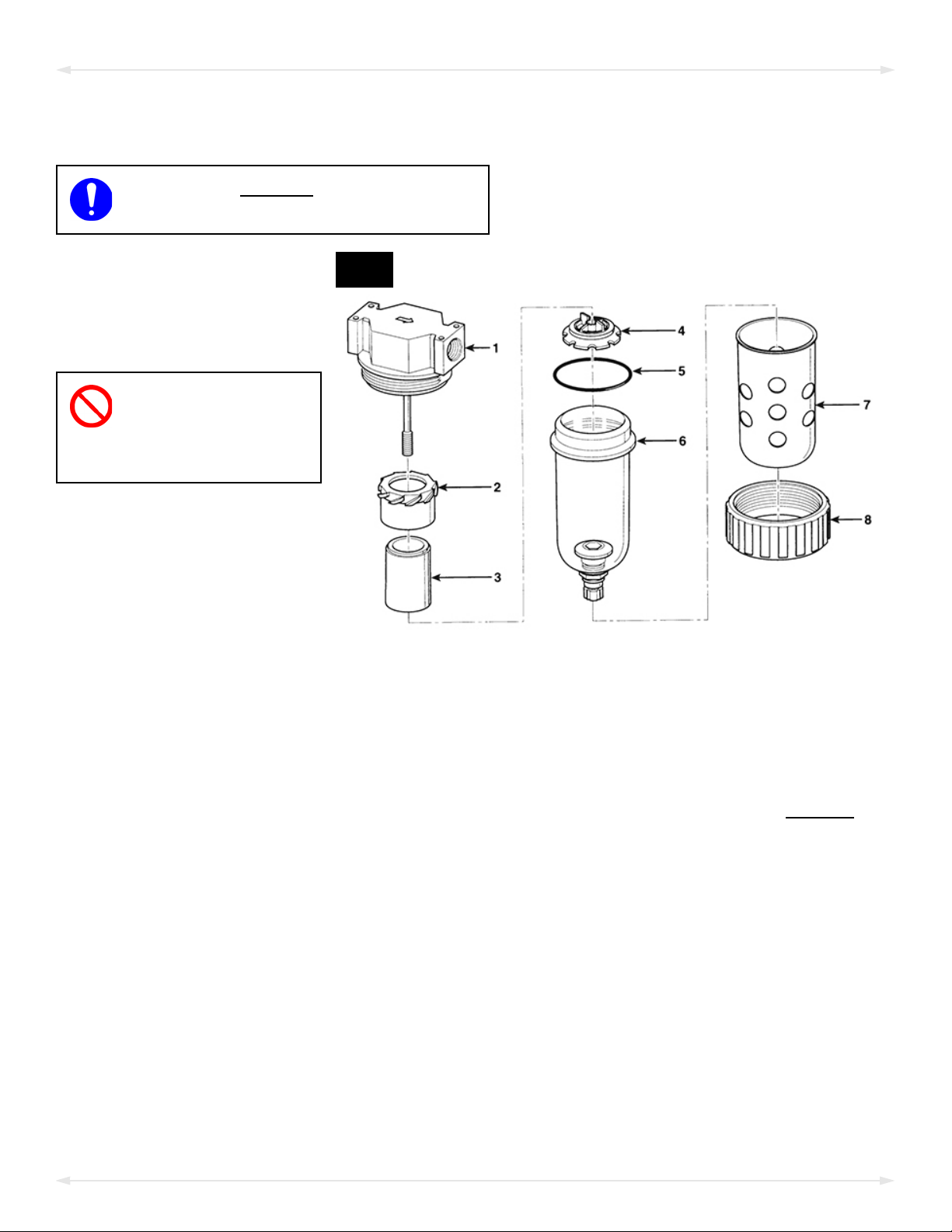
AIR FILTER MAINTENANCE – 1 OZ BOWL SIZE ...................................................4
Filter Service Procedure......................................................................................................4
AIR FILTER MAINTENANCE −4.4 OZ BOWL SIZE ................................................6
Filter Service Procedure......................................................................................................6
VACUUM PUMP MAINTENANCE −MODEL 0523...............................................8
Disassembly/Reassembly Procedure ..................................................................................8
VACUUM PUMP MAINTENANCE −MODEL 3032 OR 2032.................................9
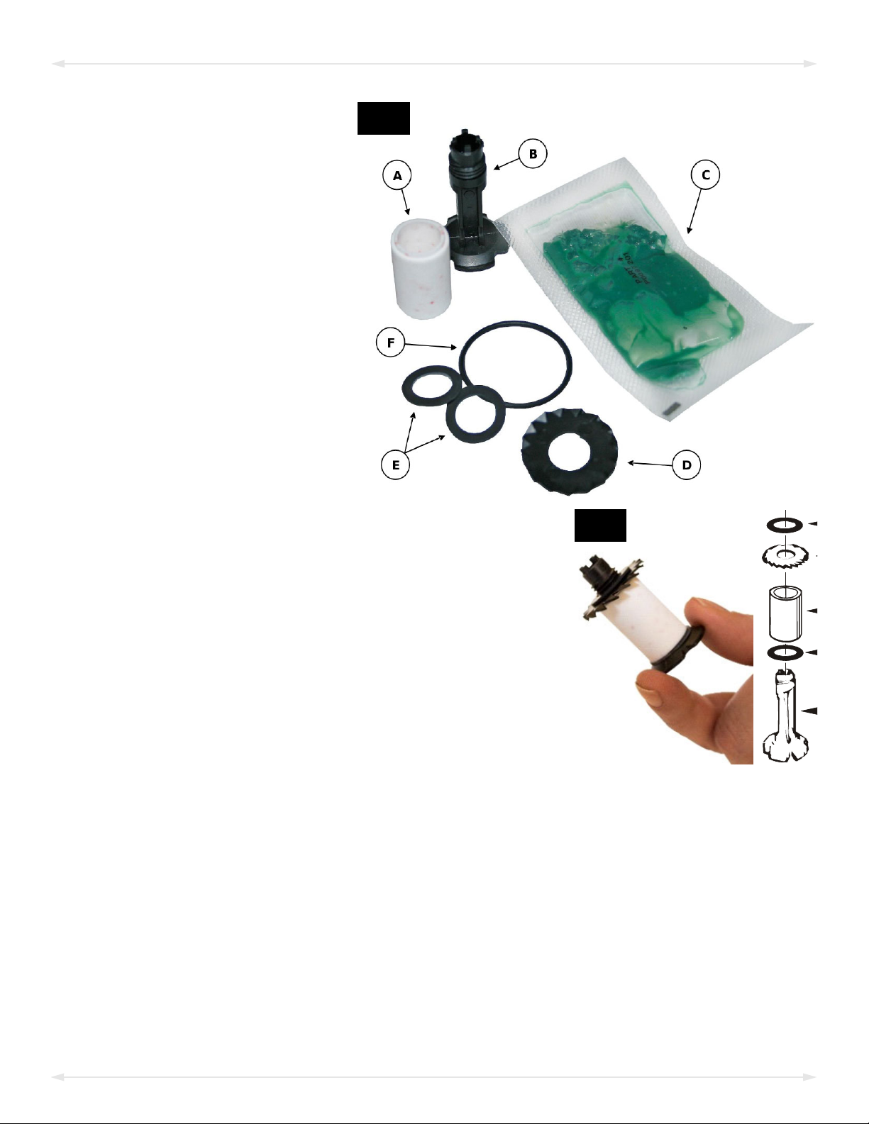
VACUUM PUMP MAINTENANCE −MODEL MP27 ...........................................11
Removing the Head and Valve Plate .................................................................................12
Replacing the Intake Valve and Sleeve O-Ring ..................................................................12
Replacing the Exhaust Valve and Head O-Ring .................................................................12
Disassembling the Piston Assembly..................................................................................12
Replacing the Sleeve and Cup...........................................................................................13
Installing the Valve Plate and Head...................................................................................13
VACUUM SWITCH ADJUSTMENT....................................................................14
LINEAR TILT ACTUATOR ADJUSTMENT ............................................................15
REPLACEMENT PARTS...........................................................................16
TABLE OF CONTENTS

AC: #35275 Rev 3.1/6-222
BEFORE SERVICING LIFTER
Disconnect power source
before servicing lifter.
1A 1B
Disconnect the
electrical
connectors (figs.
1A-B).
Service personnel must read and understand the lifter’s OPERATING INSTRUCTIONS ‒especially
“INSPECTIONS AND TESTS” and “MAINTENANCE” sections ‒before servicing the vacuum lifter.
Many of the following discussions assume knowledge of the OPERATING INSTRUCTIONS.
Note: The relevant wiring diagrams are shown in the lifter’s OPERATING INSTRUCTIONS, for
reference when servicing or troubleshooting the lifter.
SERVICE SCHEDULE
Service must be performed whenever a deficiency is indicated by routine inspections or tests.
Follow the “INSPECTIONS AND TESTS” section of the OPERATING INSTRUCTIONS. Any service
warranted must be performed before resuming normal operation of the lifter.

Rev 3.1/6-22 AC: #352753
Features shown here are underlined on their first appearance in each section to follow.
1 LIFT POINT 2 VACUUM LIFT LIGHT 3 POWERSWITCH
4PENDANTBASKET 5 VACUUM PAD 6 PADFRAME
7 ROTATION RELEASE LEVER 8 VACUUM RELEASE BUTTON1
1...... Some lifters have a lever-style Vacuum Control Valve instead of a Vacuum Release Button.
9 TILT TOGGLE SWITCH
10 MOVABLE CONTROL PENDANT 11 AIR FILTER 12 Enclosure w/ VACUUM SWITCH
13 VACUUM GAUGE 14 LIFT BAR 15 VACUUM RESERVE TANK
16 TILT ACTUATOR 17 VACUUM PUMP 18 CONTROL HANDLE
Note: A standard MRPT89AC is shown.1
1..... Some components may not be relevant or they may have a different location, depending on the lifter in question.
SERVICE FEATURES

AC: #35275 Rev 3.1/6-224
SERVICE PROCEDURES
AIR FILTER MAINTENANCE – 1 OZ BOWL SIZE
Inspect each air filter regularly, and service
when necessary.
1A
A
B
Immediately remove liquid or other contaminates found in
the filter bowl (A in fig. 1A), to prevent contact with the
filter element (C in fig. 2A).
Never use bowl drain (circled in fig. 1A) to
remove liquid, because this could cause air leak.
Replace the filter element whenever:
• It has an overall dirty appearance.
• There is a noticeable increase in the time required to attain full vacuum.
Filter Service Procedure
1) Unscrew the bowl (item A in fig. 1A) from the body (item B in fig. 1A) of the air filter.
Note: To protect air-line fittings from damage, hold the body while turning the bowl.
2)
2A
C
Determine whether the filter element (item C in fig. 2A) needs
to be replaced (see above).
• If so, proceed to step 3.
• If not, remove any liquid or contaminates from the bowl;
clean the old bowl seal (see step 4 on next page) with
mild soap and water; and skip to step 6.
3)
3A 3B
D
Carefully
unscrew the
element holder
(item D in fig.
3A) and remove
all internal parts
(fig. 3B).

Rev 3.1/6-22 AC: #352755
4)
4A
Identify the parts in the Filter
Element Kit (#16134),
including the element (item A
in fig. 4A), element holder (B),
lubricant (C), deflector (D),
element gaskets (E), bowl seal
(F). Then dispose of the
corresponding old parts.
5)
5A
Place the new element gaskets, element and deflector on
the element holder as shown in fig. 5A. Then screw the
assembly back into the filter body.
Note: Tighten gently ‒finger-tight.
6) Clean the bowl, using mild soap and water only.
Caution: Do not use any other cleaning agents.
7) Lubricate the new or cleaned bowl seal using a mineral-
based oil or grease, such as that provided in the filter
element kit.
Caution: Do not use synthetic oils, such as esters, and do
not use silicones.
Then place the bowl seal around the rim of the bowl.
8) Screw the bowl back into the body. Hand-tighten only.
Caution: Do not contaminate the filter element with lubricant from the bowl seal.
9) Perform the “Vacuum Test” to be certain the air filter does not leak (see “INSPECTIONS
AND TESTS: TESTING” in the lifter's OPERATING INSTRUCTIONS).
Note: Repeat this procedure for any other filter of the same type.
SERVICE PROCEDURES

AC: #35275 Rev 3.1/6-226
SERVICE PROCEDURES
AIR FILTER MAINTENANCE −4.4 OZ BOWL SIZE
Inspect each air filter regularly, and
service when necessary.
1A
Immediately remove liquid
found in the filter bowl, to
prevent contact with the filter
element.
Never use bowl
drain to remove
liquid, because this could
cause air leak.
Replace the element
whenever:
• It has an overall dirty
appearance.
• There is a noticeable
increase in the time required to attain full vacuum.
Note: The Filter Element Kit (#16132) includes an element (item 3 in fig. 1A), a bowl seal (item 5)
and lubricant (not shown).
Filter Service Procedure
1) Unscrew the threaded collar (item 8 in fig. 1A) from the body (item 1) of the air filter.
Note: To protect air-line fittings from damage, hold the body while turning the collar.
2) Remove the bowl guard (item 7) and the bowl (item 6).
3) Determine whether the filter element (item 3) needs to be replaced (see above).
•If so, proceed to step 4.
•If not, remove any liquid or contaminates from the bowl; clean the old bowl seal
(item 5) with mild soap and water; and skip to step 8.
4) Unscrew the baffle (item 4), and remove the element and deflector (item 2).
5) Discard the old element and bowl seal (item 5).

Rev 3.1/6-22 AC: #352757
6) Clean the bowl and all remaining internal parts, using mild soap and water only.
Caution: Do not use any other cleaning agents.
7) Install the deflector and a new filter element. Then screw the baffle back on to hold the
element in place.
Note: Tighten gently ‒finger-tight.
8) Lubricate the new or cleaned bowl seal, using a mineral-based oil or grease, such as that
provided in the filter element kit.
Caution: Do not use synthetic oils, such as esters, and do not use silicones.
Then place the bowl seal around the rim of the bowl.
9) Install the bowl back onto the body.
Caution: Do not contaminate the filter element with lubricant from the bowl seal.
10) Install the bowl guard and the collar.
Note: Tighten the collar with 28-32 in-lbs [316-362 N-cm] of torque.
11) Perform the “Vacuum Test” to be certain the air filter does not leak (see “INSPECTIONS
AND TESTS: TESTING” in the lifter's OPERATING INSTRUCTIONS).
Note: Repeat this procedure for any other filter of the same type.
SERVICE PROCEDURES

AC: #35275 Rev 3.1/6-228
V
ACUUM
P
UMP
M
AINTENANCE
−M
ODEL
0523
Before proceeding with any maintenance, disconnect
power source and allow pump to cool.
Disassembly/Reassembly Procedure
(includes replacing air filters, vanes and gasket; see “REPLACEMENT PARTS”).
1)
1 SHROUD 8 AIR FILTER (2x / #66175)
2 VANES (4x / #66175) 9 O-RING (2x)
3 ENDPLATE 10 END CAP (2x)
4 BOLTS FOR ENDPLATE (6x)
5 GASKET (#66175AB)
6 SOUND CHAMBER
7 BOLTS FOR SOUND
CHAMBER (5x)
Remove the end
caps, O-rings and air
filters from the
sound chamber of
the vacuum pump.
2) Remove the five
bolts and remove
the sound chamber.
Note: If any liquid is
discovered in the
sound chamber,
thoroughly dry all
interior surfaces of the pump prior to reassembly.
3) Remove the six bolts from the endplate, and separate the endplate from the rotor
housing. The shroud surrounding the rotor housing will loosen as well.
4) Note the orientation of the bevel on the vanes for step 5. Then remove the vanes by
sliding them out the end of the rotor. If needed, rotate the rotor by hand to position the
vanes for easier access.
5) Make sure that the rotor and housing are clean and free of debris. Orient the new vanes
like the old ones by matching the bevel. Then insert the new vanes by sliding them into
the empty slots in the rotor.
6) Reinstall the endplate and secureit with the six bolts previously removed.
7) Remove the gasket, and make sure that the contact surfaces between the endplate and
sound chamber are clean. Install a new gasket and reinstall the sound chamber. Then
secure the sound chamber with the five bolts previously removed.
8) Replace the air filters. Then reinstall the O-rings and end caps.
SERVICE PROCEDURES

Rev 3.1/6-22 AC: #352759
VACUUM PUMP MAINTENANCE −MODEL 3032 OR 2032
Before proceeding with any maintenance, disconnect
power source and allow pump to cool.
(for pump nos. 3032-101A-G609X; 2032-101-G616X)
If the vacuum pump takes too long to attain full vacuum, it may
require maintenance, as directed in the following disassembly/
reassembly procedure. Service or replace air filters and vanes as necessary toobtain
acceptable pump performance (see Pump Vanes/Filters Kits in “REPLACEMENT PARTS”).
Note: Inspect air filters after no more than 500 hours of operation; dirty filters must be cleaned
or replaced.
1)
1 MOTOR W/ ROTOR HOUSING 2 CAPACITOR
3 VANES (4x) 4 AIR FILTERS (2x)
5 INSERT PLATE 6 RETAINER PLATE
7 LONG RETAINER BOLT (3x) 8 SHORT RETAINER BOLT (5x)
Remove the
retainer bolts
from the vacuum
pump.
2) Remove the
retainer plate and
insert plate by
lightly tapping on
them with a small
hammer. Note:
Do not use a
screwdriver to
remove these
plates, because it
could damage
them.
3) Before removing the existing vanes, note the direction of the beveled edge, in order to
install the new vanes in the same orientation. Do not try to remove the rotor, because it
can only be serviced by the manufacturer.
4) Spray the bore and rotor with a suitable, nonpetroleum-based flushing solvent. Use a
clean, dry cloth to remove flushing solvent from these parts.
5) Place the new vanes in the rotor slots with the beveled edge in the correct orientation
(see step 3). Note: Vanes may become damaged or broken if installed incorrectly.
SERVICE PROCEDURES

AC: #35275 Rev 3.1/6-2210
6) If the air filters appear dirty, clean them with soapy water or replace them altogether,
depending on their condition. After cleaning the filters, dry them with compressed air.
Since moisture can damage the pump, be sure to avoid introducing any moisture into the
pump. When the filters are completely dry, reinstall them in the rotor housing.
Otherwise, install new filters.
7) Place a sheet of fine emery cloth on a smooth, flat surface and rub both sides of the
insert plate on the emery cloth to remove any burrs. Use a clean, dry cloth to remove any
dust from the insert plate. Reinstall the insert plate, placing the unused side facing the
pump vanes.
8) Repeat step 7 with the face of the retainer plate. Use a clean, dry cloth to remove any
dust from the retainer plate and reinstall it.
9) Reinstall the retainer bolts and tighten them to 28-36 in-lbs (3.1-4.1 N-m) of torque.
SERVICE PROCEDURES

Rev 3.1/6-22 AC: #3527511
VACUUM PUMP MAINTENANCE −MODEL MP27
Before proceeding with any maintenance,
disconnect power source and allow pump to cool.
If the
vacuum pump
takes too long to attain full vacuum,
clean the exterior of the pump and replace
worn parts as necessary to obtain acceptable pump performance (see
“REPLACEMENT PARTS”
).
#66126
shown
#66126
#66143
Reference Availability Qty. for #66143 Qty. for #66126 Description
A4 8 Head Screw
B1 2 Head
C1 2 Head O-ring
D1 2 Exhaust Valve Kit (valve flapper, restraint and screw)
E1 2 Valve Plate
F1 2 Sleeve O-Ring
G1 2 Intake Valve Kit (valve flapper, keeper and screw)
H1 2 Cylinder Sleeve
I1 2 Retainer Screw
J1 2 Retainer Plate
K1 2 Piston Cup
Nonstocked Item Included in service kit #66179AM
SERVICE PROCEDURES

AC: #35275 Rev 3.1/6-2212
Note: The steps in the sections below and on page 13 describe procedures for servicing single-
head pump #66143. Repeat each step when servicing dual-head pump #66126.
Removing the Head and Valve Plate
1) Remove the head screws (A) and the pump head (B). Note the orientation of the head for
reassembly.
2) Carefully separate the valve plate (E) from the bottom of the pump head (B) and the top
of the cylinder sleeve (H). Note the orientation of the plate tabs for reassembly.
3) Remove the head O-ring (C) and sleeve O-ring (F), and discard them.
Replacing the Intake Valve and Sleeve O-Ring
4) Remove the old valve screw, keeper and flapper (G) and discard them.
5) Clean the lower surfaces of the valve plate (E) with a soft cloth.
6) Install the new valve flapper, keeper (so “X” is visible) and screw (G) as shown. Tighten
the screw with 18 in-lbs [2 N-m] of torque.
7) Install new sleeve O-ring (F) in the valve plate (E). Make sure to seat the O-ring firmly in
the groove.
Replacing the Exhaust Valve and Head O-Ring
8) Remove the old valve screw, restraint and flapper (D) and discard them.
9) Clean the upper surfaces of the valve plate (E) with a soft cloth.
10) Install the new valve flapper, restraint and screw (D) as shown. Tighten the screw with
18 in-lbs [2 N-m] of torque.
11) Install new head O-ring (C) in the valve plate (E). Make sure to seat the O-ring firmly in
the groove, without any twists.
Disassembling the Piston Assembly
12) Remove the retainer screw (I) and discard it. Note the position of the recesses in the
retainer plate (J) for reassembly.
13) Remove the cylinder sleeve (H), retainer plate (J) and piston cup (K). Discard the sleeve
and cup.
14) Clean the retainer plate (J) and top of the piston rod.
SERVICE PROCEDURES

Rev 3.1/6-22 AC: #3527513
Replacing the Sleeve and Cup
15) Place the new cylinder sleeve (H) over the piston rod.
16) Insert the new piston cup (K) into the sleeve (H) and push the cup down to the piston
rod.
17) Reinstall the retainer plate (J) on the piston rod, making sure to position it correctly.
18) Install the new retainer screw (I) and tighten it with 55 in-lbs [6.2 N-m] of torque.
Installing the Valve Plate and Head
19) Make sure the cylinder sleeve (H) is seated firmly against the pump housing. Then place
the assembled valve plate (E) in the correct orientation on the sleeve, making sure it fits
into the O-ring groove.
20) Place the head (B) in the correct orientation on the valve plate (E), making sure the plate
tabs fit in head notches.
21) Install the head screws (A) and tighten them with 55 in-lbs [6.2 N-m] of torque in a
crisscross pattern.
SERVICE PROCEDURES

AC: #35275 Rev 3.1/6-2214
VACUUM SWITCH ADJUSTMENT
The vacuum switch turns the vacuum lift light on and off as needed to indicate whether the
lifter has attained sufficient vacuum for lifting the maximum load weight, as shown on the
vacuum gauge (see “OPERATION: TOATTACH THE PADS TO ALOAD: Reading the Vacuum Gauge” in
the lifter’s OPERATING INSTRUCTIONS).
If the switch is adjusted correctly,the lift light turns on only after vacuum becomes sufficient for
lifting; and turns off again before vacuum becomes insufficient for lifting.1,2 Adjust the vacuum
switch when necessary:
1)
1B1A
Use the 1/4" open-end wrench
provided to turn the adjustment
screw (circled in fig. 1A) about
1/6th turn at a time:
• To make the lift light turn
offat a greater vacuum
level, turn the screw
counterclockwise (fig. 1B).
•
1C
To make the lift light turn
on at a lesser vacuum level, turn the screw clockwise
(fig. 1C).
2) Check lift light activity in relation to the vacuum level.3
Continue to make incremental adjustments until the vacuum
switch is functioning correctly.
1..... If the lift light turns on before vacuum is sufficient for lifting, replace the air filter’s element (see “AIR FILTER MAINTENANCE – 1 OZ BOWL SIZE”or
“AIR FILTER MAINTENANCE −4.4 OZ BOWL SIZE”). If the lift light does not turn on after vacuum is sufficient for lifting, replace the light bulb (see
“REPLACEMENT PARTS”).
2..... In order to observe lifter functions while vacuum is decreasing, it may be necessary to create a controlled leak in the vacuum system.
3..... In order to test the adjustment accurately, release the vacuum pads completely before reattaching them to a test surface.
SERVICE PROCEDURES

Rev 3.1/6-22 AC: #3527515
LINEAR TILT ACTUATOR ADJUSTMENT
The tilt actuator is prelubricated and should not require additional lubrication.1
The actuator has an intermittent-duty type motor. If the actuator is operated more than 20% of
the time or runs continuously for more than 5 minutes, a thermal overload relay will break the
power circuit. It then takes about 10 minutes before the motor cools sufficiently for the
thermal relay to close and restore power.
The brake is preset and should provide consistent braking for the tilt function. However, if the
brake friction surfaces become worn (indicated by excessive drift), contact WPG for rebuilding.
The limit switches, which control the stroke length, also are preset and should not need
adjustment. However, if adjustment is required, proceed as follows:
1)
1A
Remove the appropriate cover
plate (on actuator head, facing
screw shaft side) to expose the
limit switches (items 1 and 5 in
fig. 1A).
2) Engage the actuator until it
reaches the correct retracted
or extended position
(depending on adjustment
needed). Stop the actuator
before any parts of the
vacuum lifter come in contact
with each other.
3) Remove the nut restrainer
(item 3).
4) Turn the appropriate limit switch nut (item 2 or item 4) as needed to activate the limit
switch, allowing for drift.
5) Check actuator travel and readjust if necessary. Then reinstall the nut restrainer and
cover plate.
1..... If the actuator is not used for a week or more at a time, oil may begin to separate from the lubricant and leak out. Although this condition is not
detrimental to the actuator, you can avoid it by simply running the actuator for a few cycles each week.
SERVICE PROCEDURES

Stock No. Description Qty.
95500AM Vacuum Pump – Rotary Vane Type – 4 SCFM – 100/120/240 V AC 1
93039 Vacuum Pump – Rotary Vane Type – 2.5 SCFM – 240 V AC 1
66207 Pump Vanes/Filters Kit (for pump 93039) 1
66179AM Pump Service Kit (for pumps 66126, 66126AM, 66143) 1
66175AB Pump Gasket (for pump 95500AM) 1
66175 Pump Vanes/Filters Kit (for pump 95500AM) 1
66143 Vacuum Pump – Wobble Piston – 2.5 SCFM – 120 V AC 1
66126AM Vacuum Pump – Wobble Piston – 5 SCFM – 240 V AC 1
66126 Vacuum Pump – Wobble Piston – 5 SCFM – 120 V AC 1
65277 Vacuum Control Valve with Lever (for MRTA8-AC) 1
65275 Vacuum Control Valve with Lever (for FLEX-AC, MR4-AC, MTA4/8-AC) 1
65264M Valve Adapter (for MRTA6LP6FAC, MTA2-AC vacuum release buttons) 1
65261 Vacuum Control Valve ‒4-Way (for MRTA6LP6FAC, MTA2-AC vacuum release buttons) 1
65258 Push Button (for MRTA6LP6FAC, MRTA6LP6FAC, MTA2-AC vacuum release buttons) 1
65234 Solenoid Valve – 240 V AC – 6 W (for FLEX-AC, MR4-AC, MTA2-AC) 1
65231 Solenoid Valve ‒120 V AC ‒6 W (for CFPT-9AC, MRPT89AC, VLGG-AC) 2
65226 Solenoid Valve – 120 V AC – 6 W (for FLEX-AC, MRTA6LP6FAC, MR4-AC, MTA2-AC) 1
65212AM Check Valve – 1/4 NPT – 0.15 PSI (for MRTA6LP6FAC, MTA2-AC) 1
65212 Check Valve – 1/4 NPT – 1.00 PSI 1
65211AM Check Valve – 1/8 NPT – 0.15 PSI 1
64952 Actuator ‒1500 lbs ‒12" Stroke ‒120 V AC (for MRPT89AC, PT10/1410TAC) 1
64951 Actuator ‒1500 lbs ‒12" Stroke ‒240 V AC (for MRPT89AC, PT10/1410TAC) 1
64950 Actuator ‒1500 lbs ‒6" Stroke ‒120 V AC (for CFPT-9AC, PT4-AC) 1
64948 Actuator ‒1500 lbs ‒6" Stroke ‒240 V AC (for CFPT-9AC) 1
64461 Circuit Breaker ‒10 A 1
64459MZ Circuit Breaker ‒8 A 1
64459 Circuit Breaker – 5 A 1
64355 Adjustable Time Delay Relay ‒18-240 V AC ‒1.5 A (for pump 93038) 1
64289 Bulb ‒24 V ‒Bayonet (for vacuum lift light on CFPT-9AC, MRPT89AC, VLGG-AC) 1
64284 Bulb ‒6.3V ‒Bayonet (for vacuum lift light on MRTA8-AC) 1
64262 Green Lens (for vacuum lift light) 1
64236 Vacuum Switch – 1/4 NPT 1
64191 Contact Block (for rotary power switch) 1
64176 Power Switch – On/Off Toggle (for MR4-AC, MRTA6LP6FAC, MTA2-AC) 1
56052 Solenoid Valve Manifold Assembly – 24 V AC (for CFPT-9AC, MRPT89AC, PT4-AC, PT10/1410TAC, VLGG-
AC) 1
20270 1/4" Open-End Wrench (for adjusting vacuum switch) 1
20050 Pad Ring Installation Tool 1
16134 Filter Element Kit (for 1 oz bowl size air filter) 1
16132 Filter Element Kit (for 4.4 oz bowl size air filter) 1
15930 Vacuum Gauge – 1/4 NPT – LM Type (for MTA2-AC, VLGG-AC) 1
15910 Vacuum Gauge – 1/8 NPT – CBM Type (for other models) 1
15650 360° Rotating Union – 1/4 NPT (for MR4-AC, MRPT89AC) 1
AC: #35275 Rev 3.1/6-2216
See OPERATING INSTRUCTIONS for additional parts.
SERVICE ONLY WITH IDENTICAL REPLACEMENT PARTS,
AVAILABLE AT WPG.COM OR THROUGH AN AUTHORIZED WPG DEALER
REPLACEMENT PARTS
Table of contents
Other WPG Industrial Equipment manuals

WPG
WPG FLEXR Series User manual

WPG
WPG TL3AM User manual

WPG
WPG FLEXR Series User manual

WPG
WPG MRTALP4625DC3 User manual

WPG
WPG MRTALPCH611DC3 User manual

WPG
WPG MRT4 Series User manual

WPG
WPG N4300 Series Operating instructions

WPG
WPG LJ6VH User manual

WPG
WPG PT1010TAC User manual

WPG
WPG MRT4 Series User manual