10 |Bosch Inverter Ducted Packaged Heat Pump Installation & Operation Manual
03.2019 | BTC 761701105 AData subject to change
4 Installation
4.1 Pre-Installation
Before installation, carefully check the following:
1. Unit should be installed in accordance with national and local
safety codes, including but not limited to ANSI/NFPS No. 70, local
plumbing and wastewater codes and any other applicable codes.
2. For rooftop installation, be sure the structure has enough strength
to support the weight of unit. Unit must be installed on a field
supplied roof curb or rack and leveled.
3. For ground level installation, a field supplied level slab must be
used.
4. Condenser airflow should not be restricted.
5. On applications when a roof curb is used, the unit must be
positioned on the curb so the front of the unit is tight against
the curb. If the unit is to be mounted on a curb in a downflow
application, refer to Figure 13, and convert panels prior to rigging
and lifting. The panel removal process may require the unit to be on
the ground.
4.2 Rigging And Lifting
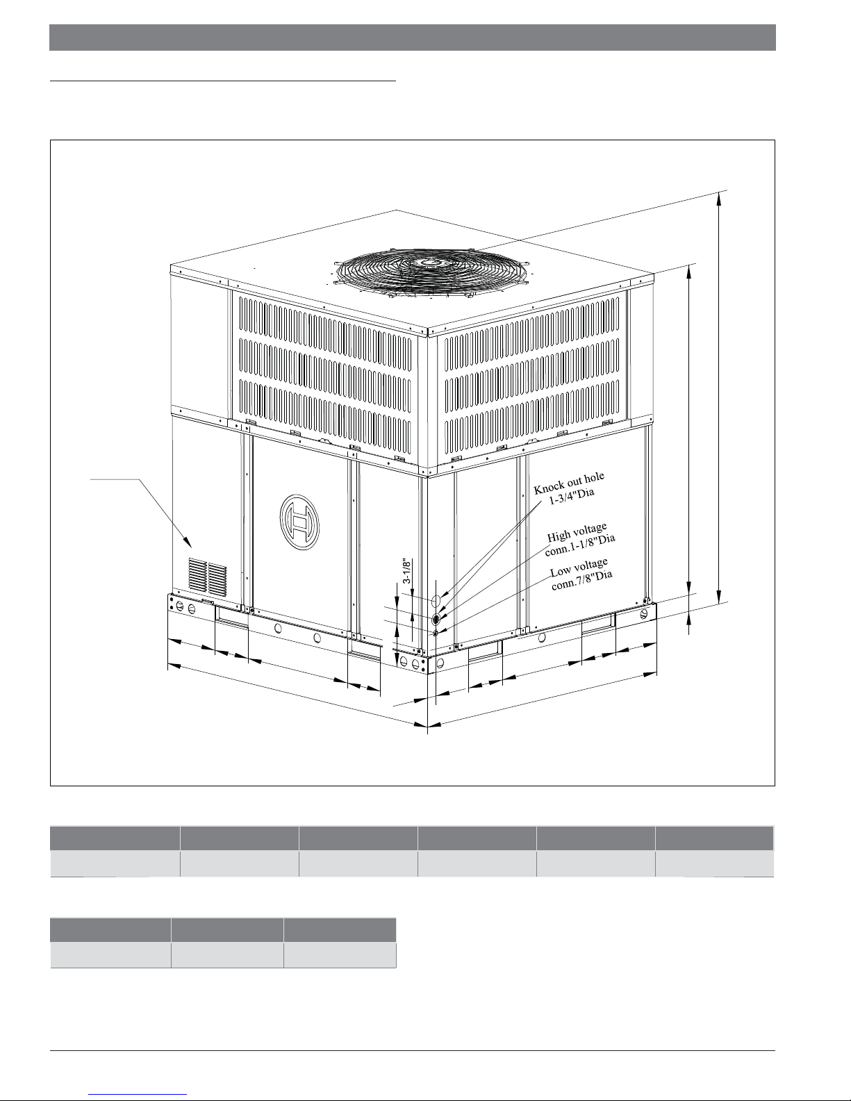
Figure 5
Unit Height
Minimum Height 36"
Exercise care when moving the unit. Do not remove any packaging until
the unit is near the place of installation. Rig the unit by attaching chain or
cable slings to the lifting holes provided in the base rails. Spreader bars,
whose length exceeds the largest dimension across the unit, MUST be
used across the top of the unit.
When rigging/lifting the unit, the minimum height between the top of the
rigging cables' connection point and top of unit should be 36 in. Refer to
Figure 5.
CAUTION:
Before lifting, make sure the unit weight is
distributed equally on the rigging cables so it will lift
evenly.
CAUTION:
All panels must be secured in place when the unit is
lifted. The condenser coils should be protected from
rigging cable damage with plywood or other suitable
material.
4.3 Location Restrictions
Ensure the top discharge area is unrestricted for at least 60 inches above
the unit.
Do not locate outdoor unit near bedrooms since normal operational noise
levels may be disturbing to building occupants.
Position unit to allow adequate space for unobstructed airflow, wiring, and
serviceability.
Do not restrict outdoor airflow. An air restriction at either the outdoor air
inlet or the fan discharge may be detrimental to compressor life.
Do not place the unit where water, ice, or snow from an overhang or roof
will damage or flood the unit. Do not install the unit on carpeting or other
combustible materials. Slab-mounted units should be at least 2 in. (51
mm) above the highest expected water and runoff levels. Do not use unit if
it has been under water.
Maintain a distance of 24 inches between units. Position unit so water,
snow, or ice from roof or overhang cannot fall directly on unit.
See Fig. 7 and Fig. 8 for minimum clearance requirements.
Cold climate considerations (heat pump only)
NOTICE:
Precautions must be taken for units being installed
in areas where snow accumulation and prolonged
below-freezing temperatures occur.