manuals.online logo
Brands
  1. Home
  2. •
  3. Brands
  4. •
  5. Bosch
  6. •
  7. Receiver
  8. •
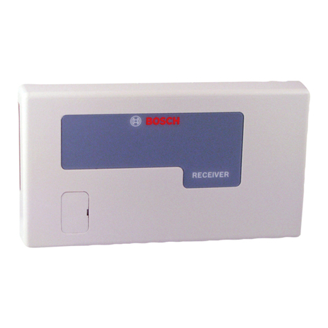
  9. Bosch Conettix D6600 Owner's manual

Bosch Conettix D6600 Owner's manual

D6600/D6100IPv6
UL864 & UL1610 Installation
Supplement
Aug 2012
This document supplements the Conettix D6600/D6100IPv6 Installation and Operation Guide
(P/N: 4998122704-08).
1.0 Network Ethernet Module
In the D6600/D6100IPv6 Installation and Operation Guide (4998122704-08), all references to
Network Ethernet Module are the ITS-D6686-UL and its associated documentation (the Conettix
D6686 Ethernet Network Adapter Installation Guide [F01U269888-01]).
2.0 Additional Printer Specification
In Section 6.0 Printer Specifications of the D6600/D6100IPv6i Installation and Operation Guide
(4998122704-08), include the following specification:
•The printer must be installed in the same room as the D6600/D6100IPv6.
3.0 Installation
3.1 All Installations
In Section 7.0 Installation of the D6600/D6100IPv6 Installation and Operation Guide (4998122704-
08), include the following installation requirements and notes:
•Install the D6600/D6100IPv6 Communications Receiver/Gateway according to the National
Electrical Code (NFPA 70), the National Fire Alarm Code (NFPA 72), and the local Authority
Having Jurisdiction (AHJ).
UL Standard 827 requires that any central station listed for NFPA 72, Central Station Protective
Signaling, UL Central Station Burglary or Police S
tation Connect Service must have a redundant
receiver on the premises to use if the primary receiver malfunctions.
The D6640
Telephone Line Card
is not intended for new installations, but is suitable for existing or
retrofit sites.
Equipment
between Ethernet Interface Modules and the D6600/D6100IPv6 must be UL Listed
Information Technology Equipment
(ITE).
A “COMM FAIL” message
might indicate a compromise attempt.
To meet requirement UL 1610, Section 63.1: The number of separate signals on a single channel
is
limited to 1000. Exception: There is no limit to the number of signals if the central
-
station equipment
is completely duplicated by standby equipment and a swi
tchover can be accomplished in not more
than
90 sec without loss of signals during this period.
The
D6100IPv6 was tested by UL at 120VAC, 60 Hz.
UL864 & UL1610 Installation Supplement
© Bosch Security Systems, Inc., 2012 Page 2 F01U134241-03
Network Communication - The D6600/D6100IPv6 receiver was evaluated for communication over
Third Party Data Networks for the following services when used with a compatible control unit:
•Standard Line Security for Central Station Burglar Alarm Systems according to UL 1610 and
UL 365
•Phone lines have not been evaluated for line security
•In order to implement the Standard or Encrypted Line Security over the private or public IP
networks, the AES Library must be version TBD. The AES Library was evaluated for 128-bit,
192-bit, and 256-bit encryption.
•Supervision signals between premises alarULm equipment and supervising station alarm
receiver equipment shall be managed by the supervising station receiving equipment and
not an intermediary network agent, device or service.
•To meet UL Standard 827, you must be able to switch from one receiver to a standby
receiver within 30 sec, and then repair the faulty receiver and return it to service within
30 min.
•NFPA 72 requires that if more than eight telephone lines are used, the receiving equipment
must be completely duplicated so that switchover from non-functioning to functioning
equipment can occur within 30 sec (per NFPA 72-2002 8.5.3.2.2.1 Paragraph C).
You must program the parameters described in Table 1:
Table 1: Parameters to Set
Programming Item Parameter to Set Location in Operation &
Inst. Manual
2.2.21 Buzzer Set to 1to sound on all events. May be set to 3
when used with an automation system to sound
only when the automation link fails.
Section 10.1.6
2.2.33 External
Parallel Printer
Set to 1to print all events. May be set to 3when
used with an automation system.
Section 10.1.7
2.2.34 Battery
Supervision
Set to 1to activate. Section 8.0
3.1.2.1 Phone
Supervision
Set to 1to enable. Section 4.1.3
3.2 Burglar Alarm Applications
For commercial fire and burglary, proprietary and central station application
s that use BIS, the BIS
application
must be installed on the Listed Bosch model B-010 computer with Bosch model B-008
monitor and SC9002 printer connected.
Install the D6600/D6100IPv6 according to UL Standard 827 for Central Station Burglar Alarm
Systems. Use the D6600/D6100IPv6 in a central station that has backup AC power (according to
UL 827) to supervise certificated accounts.
UL864 & UL1610 Installation Supplement
© Bosch Security Systems, Inc., 2012 Page 3 F01U134241-03
Terminals for connection of external batteries are on the rear of the receiver (Figure 1 on page 3).
Figure 1: Location of D6100IPv6 Battery Terminals and D6600 Battery
Connector
Receivers are not shown to scale.
3.3 Fire Alarm Applications
The D6600/D6100IPv6 can be used for Central Station Protective Signaling when it is installed and
used in compliance with NFPA 72 and ANSI/NFPA 70. Installation limits for digital alarm
communicator receivers (DACR) are under the local AHJ.
3.4 Rack Mount Instructions
Maintain a 6.5 mm (0.25 in.) gap, or greater, between power limited and non-power limited
circuit wiring.
The D6600 and D6100IPv6 must be installed in a rack.
The D6100IPv6 installation must consist of the following:
•D6100IPv6 Communication Gateway Receiver
•D6100RMK Rack Mount Kit
•GlobTek, Inc. Model DA-42-18L Transformer
Plug the D6600 AC cord or the D6100IPv6 AC transformer into an outlet inside the rack only if the
outlet is wired according to Article 760 of the NEC. Rack mounting is required (according to NFPA
72-2002 4.4.1.4.2.1) to meet the mechanical protection requirement when using the type of AC cord
provided with the D6600. A UL Listed rack is required for fire protective service.
4.0 Standby Power
4.1 Connecting External Batteries
Use only approved standby batteries. Battery wiring must run from the receiver through the UL
Listed rack, exit from the rack through a conduit connection, and terminate at a UL Listed battery
enclosure suitable for the size and number of batteries used.
4.2 Uninterruptible Power Supply (UPS) Requirements
A UL1481 Listed UPS for Commercial Fire Use is required when using the D6600.
When using a UPS with the D6100IPv6, a UL1481 Listed UPS for Commercial Fire Use is required.
5.0 Input and Output Ports
5.1 UPS Monitoring through CPU Programmable Input Ports
Wiring must run from the receiver through the UL Listed rack, exit from the rack through a conduit
connection, and terminate at the external UPS for UL applications.
© Bosch Security Systems, Inc., 2012
130 Perinton Parkway, Fairport, NY 14450 USA
www.boschsecurity.com
F01U134241-03
UL864 & UL1610 Installation Supplement
10/12
Page
4 of 4
6.0 Specifications
In Section 16.0 Specifications of the D6600/D6100IPv6 Installation and Operation Guide
(4998122704-08), include the following specification:
D6100IPv6 Power
Input
AC Nominal Operating Range
Use the GlobTek, Inc. Model DA-42-18L transformer.
Input voltage: 120VAC 60Hz 0.44 A maximum

Other manuals for Conettix D6600

7

This manual suits for next models

1

Other Bosch Receiver manuals

Bosch LR 2 Professional User manual

Bosch

Bosch LR 2 Professional User manual

Bosch Radion B810 User manual

Bosch

Bosch Radion B810 User manual

Bosch ISW-EN4200 Serial User manual

Bosch

Bosch ISW-EN4200 Serial User manual

Bosch LE10 User manual

Bosch

Bosch LE10 User manual

Bosch EN4216R User manual

Bosch

Bosch EN4216R User manual

Bosch RF3224 User manual

Bosch

Bosch RF3224 User manual

Bosch RFRC-OPT User manual

Bosch

Bosch RFRC-OPT User manual

Bosch RE005EV2 User manual

Bosch

Bosch RE005EV2 User manual

Bosch Radion B810 User manual

Bosch

Bosch Radion B810 User manual

Bosch LTC 8561 Series User manual

Bosch

Bosch LTC 8561 Series User manual

Bosch Professional LR 60 User manual

Bosch

Bosch Professional LR 60 User manual

Bosch EKOM 11 User manual

Bosch

Bosch EKOM 11 User manual

Bosch RF3212E User manual

Bosch

Bosch RF3212E User manual

Bosch LR 1 Professional User manual

Bosch

Bosch LR 1 Professional User manual

Bosch Coach smartPanel NAFTA 7 620 210 046 Technical manual

Bosch

Bosch Coach smartPanel NAFTA 7 620 210 046 Technical manual

Bosch RFRC-OPT User manual

Bosch

Bosch RFRC-OPT User manual

Bosch LR 6 User manual

Bosch

Bosch LR 6 User manual

Bosch RFRC-OPT User manual

Bosch

Bosch RFRC-OPT User manual

Bosch RE005EV2 User manual

Bosch

Bosch RE005EV2 User manual

Bosch GML 10,8 V-LI User manual

Bosch

Bosch GML 10,8 V-LI User manual

Bosch WE800EV2 RF User manual

Bosch

Bosch WE800EV2 RF User manual

Bosch LE10 User manual

Bosch

Bosch LE10 User manual

Bosch BLE 130 Professional User manual

Bosch

Bosch BLE 130 Professional User manual

Bosch ISW-EN4216R User manual

Bosch

Bosch ISW-EN4216R User manual

Popular Receiver manuals by other brands

Pulsar TCF-10B System manual

Pulsar

Pulsar TCF-10B System manual

Allmatic B.RO MINI 1CH manual

Allmatic

Allmatic B.RO MINI 1CH manual

FrSky L9R instruction manual

FrSky

FrSky L9R instruction manual

Denon AVR 788 - AV Receiver Setup guide

Denon

Denon AVR 788 - AV Receiver Setup guide

Zinwell ZMT-620HD Quick setup guide

Zinwell

Zinwell ZMT-620HD Quick setup guide

Voscom VOS-1HD-ADCET/R Series installation manual

Voscom

Voscom VOS-1HD-ADCET/R Series installation manual

Lodar 92 Series Wiring instructions

Lodar

Lodar 92 Series Wiring instructions

GRAUPNER HoTT GR-18 user manual

GRAUPNER

GRAUPNER HoTT GR-18 user manual

Equitel A115 user manual

Equitel

Equitel A115 user manual

Denon AVR-1713 owner's manual

Denon

Denon AVR-1713 owner's manual

Renishaw OMI-2T quick start guide

Renishaw

Renishaw OMI-2T quick start guide

Onkyo TX-SR55 instruction manual

Onkyo

Onkyo TX-SR55 instruction manual

CAME re432tw installation manual

CAME

CAME re432tw installation manual

HP EN5000 Start here

HP

HP EN5000 Start here

AMP CDR1 Operation manual

AMP

AMP CDR1 Operation manual

Pioneer PDP-R04E Service manual

Pioneer

Pioneer PDP-R04E Service manual

CHC P3E Getting started guide

CHC

CHC P3E Getting started guide

Harman Kardon AVR 25 II owner's manual

Harman Kardon

Harman Kardon AVR 25 II owner's manual

manuals.online logo
manuals.online logoBrands
  • About & Mission
  • Contact us
  • Privacy Policy
  • Terms and Conditions

Copyright 2025 Manuals.Online. All Rights Reserved.