manuals.online logo
Brands
  1. Home
  2. •
  3. Brands
  4. •
  5. Bosch
  6. •
  7. Security Sensor
  8. •
  9. Bosch DS840LSN User manual

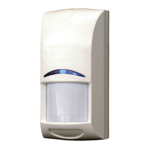
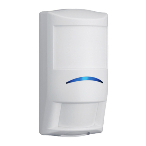
Bosch DS840LSN User manual

www.boschsecurity.com
© 2006 Bosch Security Systems, Inc.
4998132113-02 1
TriTech®PIR/Microwave
Intrusion Detector
with LSN Interface
Installation Instructions
Installationsanleitungen für
TriTech® PIR/Mikrowellen-
einbruchmelder mit
LSN-Schnittstelle
DS840LSN
£ 45 kg (100 lbs)
DS840LSN
DS840LSN-C
DS840LSN-F5
2 - P/N: 15053
2 - P/N: 24584
1 - P/N: 36145
1 - P/N: 21901
2 m - 2,6 m
(6.6 t - 8.5 t)
TriTech®and Pet Friendly®are
registered trademarks of Bosch
Security Systems, Inc. in the United
States.
1 2
3
4 5
B335
£ 45 kg (100 lbs)
Apply the pet filter to avoid nuisance alarms caused by pets such
as one dog (up to 45 kg [100 lbs]), up to 10 cats, small rodents,
or flying birds.
Installieren Sie den Haustierfilter, um durch Haustiere
ausgelöste Fehlalarme (wie z. B. einen Hund bis zu 45 kg,
bis zu 10 Katzen, kleine Nagetiere oder vorbeifliegende
Vögel) zu vermeiden.
Nicht für VdS Anlagen.
© 2006 Bosch Security Systems, Inc.
4998132113-02
2
A1 B1 A2 B2 SP SP SH
12 m (40 t)
2,0 m (6.6 ft)
£45 kg (100 lbs)
-4o
2,3 m (7.6 ft) -8o
2,6 m (8.5 ft) -8o
12
0 t 40
0 m
3
0 m
2
10
0 t
6.5
Side View
Seitenansicht
Mirror vertically adjusted to -4°
Vertikale Spiegeleinstellung au -4°
1 2 3 4 5 6 7 8 9
10
15
11
16
12
17
13 14
0 t
0 m
40
12
0 m
6
6
Ansicht von oben
Top View
20
20
0 t
25
7.5
15
17
16
10
11
12
13
14
2
1
4
3
5
7
6
9
8
6 8
119 10
From previous LSN element
Vom vorherigen LSN-Element
To next LSN element
Zum nächsten LSN-Element
Spare
Reserve
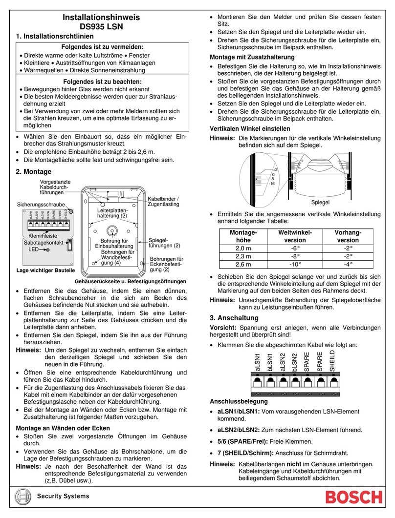
Do not coil excess wire inside enclosure.
After connecting all the wires, plug each wire
entrance with a foam plug.
Überschüssigen Draht nicht im
Gehäuse aufwickeln.
Nach Anschluss aller Kabel
den Kabeleingang mit der
Schaumstoffdichtung verschließen.
Microwave PIR Pet filtered areas
Mikrowellen-
system
PIR Haustiergefilterte
Bereiche
Pattern Masking: For specialized
coverage areas, mask the PIR
coverage pattern by applying
masking tape or electrical tape on the
mirror segments.
Abdeckung des Überwachungs-
bereichs: Für besondere
Überwachungs-bereiche
die Spiegelsegmente des
PIR-Überwachungsbereichs
mit Abdeckklebeband oder
Elektrikerband abkleben.
Shield Wire
Abschirmungskabel
12
12
7
0.8 mm to 1.8 mm
22 AWG to 14 AWG
© 2006 Bosch Security Systems, Inc.
4998132113-02
3
No activity or walk test
disabled. Red, yellow, green: Power up Red: Dual alarm Yellow: Microwave
alarm
Green: PIR
alarm
Keine Aktivität oder
Gehtest deaktiviert. Rot, Gelb, Grün: Starten Rot: Doppelalarm Gelb: Mikrowellen-
alarm
Grün: PIR-
Alarm
LED Operation
LED-Funktion
Walk Test
Gehtest
The red alarm LED can be set to continuously flash to indicate alarmed detectors
during an armed period (refer to your control panel’s operating instructions for more
information).
If the microwave fails, the PIR mode activates. The control panel is notified through
the LSN bus.
Die rote Alarm-LED kann auf ständiges Blinken eingestellt werden, um
ausgelöste Melder im scharfgeschalteten Zustand anzuzeigen (siehe die
Anleitungen Ihrer Zentrale für weitere Informationen).
Falls das Mikrowellensystem ausfällt, wird der PIR-Modus aktiviert. Der
LSN-Bus benachrichtigt die Zentrale.
Enable Walk Test from the keypad. The control panel enables the LEDs on the detec-
tor. The sensitivity of the detector (standard or intermediate) must be adjusted by the
control panel. Refer to the control panel’s operating instructions for more information.
Aktivieren Sie den Gehtest von der Tastatur aus. Die Zentrale aktiviert die
LEDs am Melder. Die Empfindlichkeit des Melders (Standard- oder mittlere
Einstellung) muss an der Zentrale eingestellt werden. Siehe Anleitungen Ihrer
Zentrale für weitere Informationen.
³ 2 min
12 34
Increase microwave range slightly until required coverage is met.
Maintenance: Verify the range and coverage at least once a year.
Vergrößern Sie den Mikrowellenbereich geringfügig, bis der erforderliche Überwachungsbereich eingestellt ist.
Wartung: Überprüfen Sie die Reichweite und den Überwachungsbereich mindestens einmal pro Jahr.
© 2006 Bosch Security Systems, Inc.
4998132113-02
4
Standby Power: No internal standby battery. For each hour of
standby time needed, 4 mAh are required.
For UL Listed Installations, four hours
(16 mAh) are required.
LSN Supply Voltage: 33 V maximum
LSN Current Consumption: 4.0 mA
Alarm Signal: Alarms are reported to the control panel
through the LSN Bus.
Microwave Frequency: DS840LSN: 10.525 GHz
DS840LSN-C: 10.588 GHz (UK, France)
DS840LSN-F5: 9.35 GHz
Options: B335 Low Profile Swivel Mount Bracket
Brackets can reduce range and
increase dead zone areas.
Compliance:
FCC (DS840LSN: 10.525 GHz
FCC ID: ESV840LSN)
This device complies with Part 15 of the FCC
Rules and with RSS-210 of
Industry and Science Canada.
Operation is subject to the following
conditions:
• The device cannot cause harmful
interference.
• This device must accept any interference
received, including interference that can
cause undesirable operation.
PIR and Microwave Supervision: Every 12 h
Betriebsspannung: Keine interne Notstrombatterie. Je Stunde
Notstromversorgung sind 4 mAh erforderlich.
Für UL-zugelassene Installationen (UL listed)
sind 4 Stunden (16 mAh) erforderlich.
LSN-Spannungsversorgung: 33 V max.
Stromaufnahme LSN: 4,0 mA
Alarmausgang: Der LSN-Bus meldet Alarme an die Zentrale.
Mikrowellenfrequenz: DS840LSN: 10,525 GHz
DS840LSN-C: 10,588 GHz (GB, Frankreich)
DS840LSN-F5: 9,35 GHz
Optionen: Schwenkbare B335-Halterungen in Flachbau-
weise können die Reichweite verringern und
unbewachte Bereiche vergrößern.
Normhinweise:
FCC (DS840LSN: 10,525 GHz)
Dieses Gerät erfüllt die Anforderungen von
Teil 15 der FCC-Regeln und RSS-210 der
Industry and Science Canada.
Das Gerät darf nur unter den folgenden
Bedingungen betrieben werden:
• Dieses Gerät darf keine schädlichen
Störungen verursachen.
• Dieses Gerät muss Störungen ausgesetzt
werden können. Dazu zählen auch
Störungen, die einen unerwünschten
Betrieb verursachen.
PIR/Mikrowellen-Überwachung: Alle 12 Stunden
-20°C - +55°C
(-5°F - +130°F)
Environmental Class II
Specifications
Technische Daten
93%
70 mm
(2.75 in.)
110 mm
(4.375 in.)
45 mm
(1.75 in.)
Betriebstemperatur VdS:
-10° bis +50°C
Umgebungsbedingungen: VdS-Klasse II
Gehäuseschuzart nach IEC: IP 54
Gewicht: 93 g
Weight: 3.25 oz
Other manuals for DS840LSN

1

This manual suits for next models

2

Other Bosch Security Sensor manuals

Bosch ISC-CDL1-W15H User manual

Bosch

Bosch ISC-CDL1-W15H User manual

Bosch FAA-420-RI-ROW User manual

Bosch

Bosch FAA-420-RI-ROW User manual

Bosch RADION contact SM User manual

Bosch

Bosch RADION contact SM User manual

Bosch DM-TP-50(80) User manual

Bosch

Bosch DM-TP-50(80) User manual

Bosch TriTech+ ISC-PDL1-WA18G User manual

Bosch

Bosch TriTech+ ISC-PDL1-WA18G User manual

Bosch ISC-BPR2-WP12 User manual

Bosch

Bosch ISC-BPR2-WP12 User manual

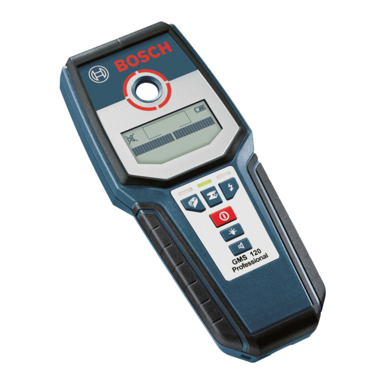
Bosch GMS 120 Professional User manual

Bosch

Bosch GMS 120 Professional User manual

Bosch ISN?SM?80 User manual

Bosch

Bosch ISN?SM?80 User manual

Bosch ISC-SM-90 User manual

Bosch

Bosch ISC-SM-90 User manual

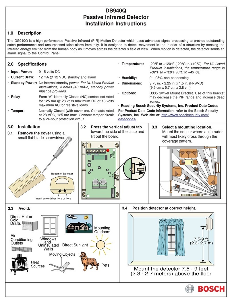
Bosch DS940Q User manual

Bosch

Bosch DS940Q User manual

Bosch DS9370 TriTech User manual

Bosch

Bosch DS9370 TriTech User manual

Bosch 200 C User manual

Bosch

Bosch 200 C User manual

Bosch LTC 2210 Series User manual

Bosch

Bosch LTC 2210 Series User manual

Bosch WEU PDO Multi User manual

Bosch

Bosch WEU PDO Multi User manual

Bosch ISA-WM-869 User manual

Bosch

Bosch ISA-WM-869 User manual

Bosch DS940P User manual

Bosch

Bosch DS940P User manual

Bosch DS840 User manual

Bosch

Bosch DS840 User manual

Bosch RF835E User manual

Bosch

Bosch RF835E User manual

Bosch Blue Line D1-P User manual

Bosch

Bosch Blue Line D1-P User manual

Bosch DS9360 TriTech User manual

Bosch

Bosch DS9360 TriTech User manual

Bosch DS9360 User manual

Bosch

Bosch DS9360 User manual

Bosch DS778 User manual

Bosch

Bosch DS778 User manual

Bosch DS940 User manual

Bosch

Bosch DS940 User manual

Bosch CRS-WM-TA869 User manual

Bosch

Bosch CRS-WM-TA869 User manual

Popular Security Sensor manuals by other brands

Lyyt 154.840UK quick start guide

Lyyt

Lyyt 154.840UK quick start guide

Niko 352-0273 Series manual

Niko

Niko 352-0273 Series manual

Lighting Technologies IS 770 quick start guide

Lighting Technologies

Lighting Technologies IS 770 quick start guide

Banner PVS28 Series instruction manual

Banner

Banner PVS28 Series instruction manual

Compur Statox 501 IR LC Brochure & specs

Compur

Compur Statox 501 IR LC Brochure & specs

ipf electronic UY000001 instruction manual

ipf electronic

ipf electronic UY000001 instruction manual

Wizmart NB326-S Installation Wiring Diagram

Wizmart

Wizmart NB326-S Installation Wiring Diagram

Interlogix AS520 Series quick start guide

Interlogix

Interlogix AS520 Series quick start guide

EMX Industries, Inc. ULT-PLG ULTRALOOP operating instructions

EMX Industries, Inc.

EMX Industries, Inc. ULT-PLG ULTRALOOP operating instructions

BorMann BDM5000 instruction manual

BorMann

BorMann BDM5000 instruction manual

Weco G5 Series user manual

Weco

Weco G5 Series user manual

Eaton Powerware Series user guide

Eaton

Eaton Powerware Series user guide

AJAX FireProtect 2 Jeweller manual

AJAX

AJAX FireProtect 2 Jeweller manual

Texecom Impaq SC-W installation manual

Texecom

Texecom Impaq SC-W installation manual

Greifzug blocstop BSO Series Operation and installation

Greifzug

Greifzug blocstop BSO Series Operation and installation

Ocean Signal rescureME MOB1 user manual

Ocean Signal

Ocean Signal rescureME MOB1 user manual

SICK Prime KTX-WP92142242ZZZZ manual

SICK

SICK Prime KTX-WP92142242ZZZZ manual

AMC SR135 quick start guide

AMC

AMC SR135 quick start guide

manuals.online logo
manuals.online logoBrands
  • About & Mission
  • Contact us
  • Privacy Policy
  • Terms and Conditions

Copyright 2025 Manuals.Online. All Rights Reserved.