Bosch SE 320 LSNi User manual

SE 320 LSNi SmartKey Arming Device
Installation Manual
SE 320 LSNi
EN

Table of Contents
2
System Description
System Overview with Functional Variants................................................................................... 3
Description of the Connections on the Control Unit...................................................................... 6
Installation Instructions
Installing System Components...................................................................................................... 8
Installing the Magnetic Contact and Bolt Contact......................................................................... 9
Connection, Switch-Point Control, Address Switches ................................................................ 10
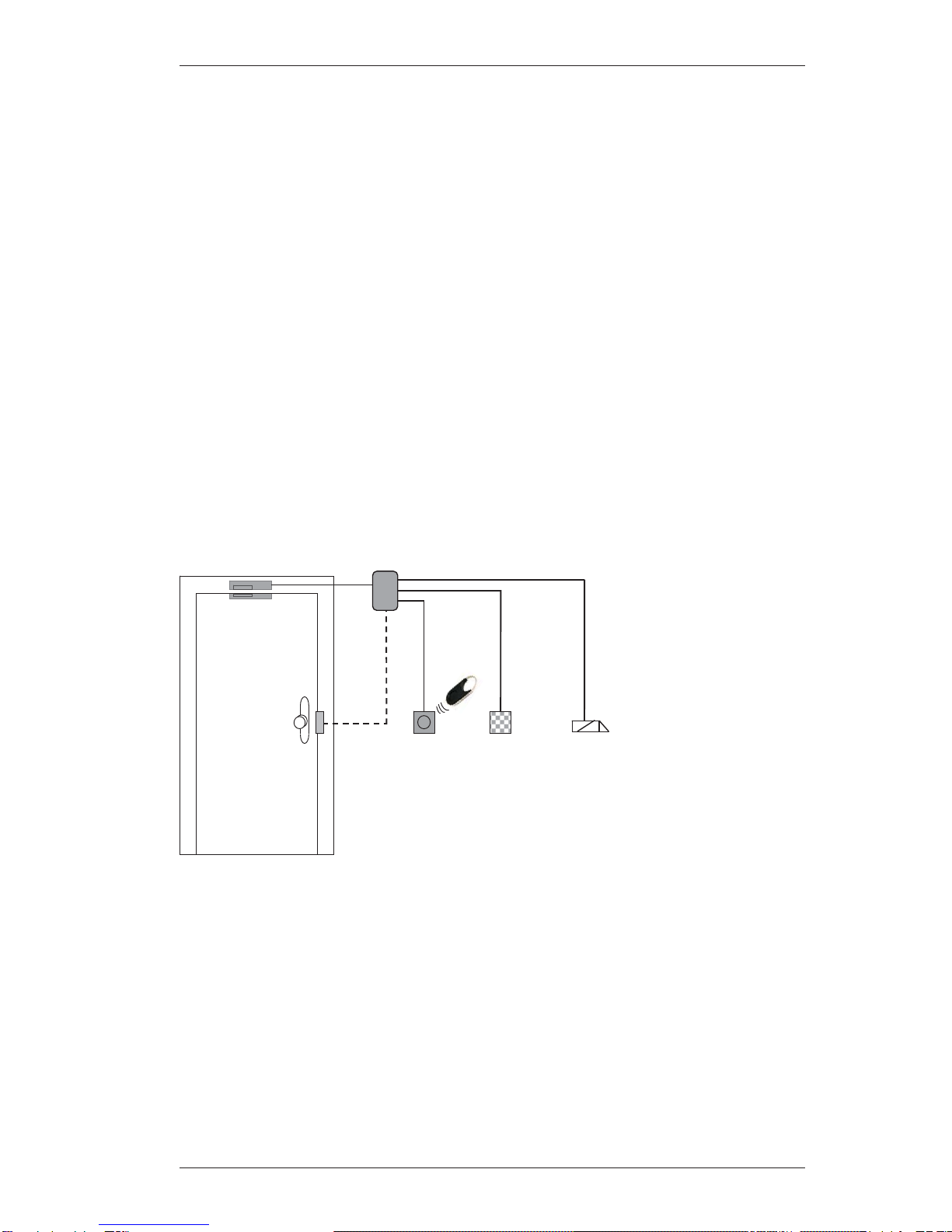
Connecting the Control Panel and Optional Components.......................................................... 11
Connecting for Operation Without an SPE Blocking Element .................................................... 12
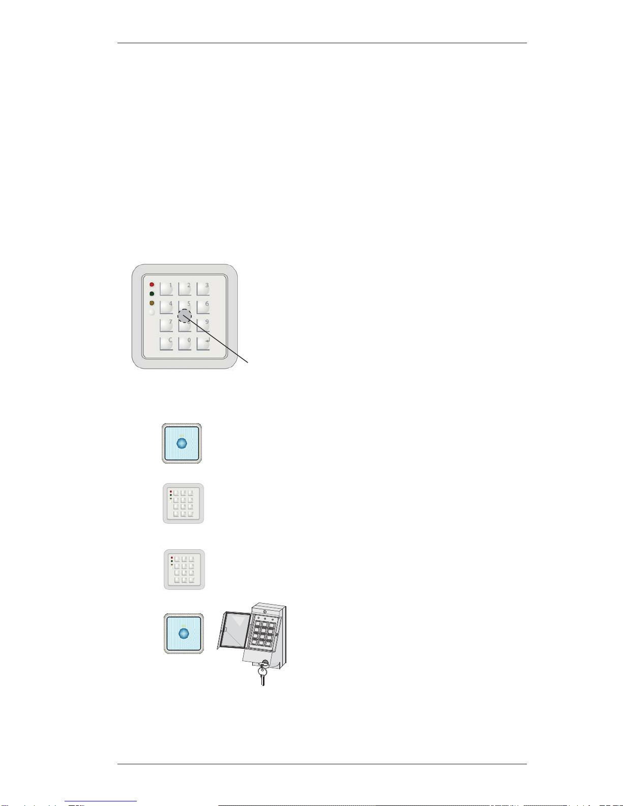
Connecting for Operation with SmartKey Code Keypad Only.................................................... 13
Connecting the SmartKey Code Keypad with Integrated Reader .............................................. 14
Connecting a Lockable Code Keypad......................................................................................... 15
Connecting a Door Opener Relay............................................................................................... 16
Connecting an E4.4 Blocking Element for Vault Doors .............................................................. 17
Connecting an E4.3 Blocking Element for Vault Doors .............................................................. 18
Function Test for SPE Blocking Element and Reader................................................................ 20
Reading In Keys and Programming the System......................................................................... 21
Starting up the SmartKey Code Keypad with Reader................................................................. 26
(or changing user codes)
Starting up the SmartKey Code Keypad Without Reader........................................................... 28
(or changing user codes)
Starting up a Lockable Code Keypad ......................................................................................... 30
(or changing user codes)
Concluding System Installation................................................................................................... 32
Operating the System
Viewing the System Status from the Reader.............................................................................. 33
Arming the System from the Reader or Code Keypad ............................................................... 34
Disarming the System from the Reader or Code Keypad........................................................... 35
Operation with SmartKey Code Keypad Only: Viewing the System Status................................ 36
Operation with SmartKey Code Keypad Only: Arming the System with the Code Keypad........ 36
Operation with SmartKey Code Keypad Only: Disarming the System with the Code Keypad... 37
Example of Operation with 4 SmartKeys/Code Keypads ........................................................... 38
Disarming for "Forced Unlocking and Alarm Display"................................................................. 38
Fault Elimination
Problems with Installation and Reading In Keys......................................................................... 39
Diagnostics Options on the Open Control Unit........................................................................... 39
Operating Problems During Normal Operation........................................................................... 40
Replacing the Bolt in the SPE Blocking Element........................................................................ 42
Notes for Maintenance and Service
General........................................................................................................................................ 43
Inspection and Maintenance....................................................................................................... 43
Loss of Keys................................................................................................................................ 44
Ordering Additional Keys ............................................................................................................ 44
Loss of the Security Card............................................................................................................ 45
Restoring the Default Settings .................................................................................................... 45
Technical Data........................................................................................................................... 46

System Description
3
System Overview with Functional Variants
The SE 320 LSNi SmartKey Arming Device is a system solution for arming and disarming intru-
sion alarm systems. The individual components of the system can be put together as required for
the intended usage. Operation types with or without the SPE blocking element are possible. Con-
trol authorizations for arming/disarming are defined during control panel programming. The sys-
tem is programmed using an appropriate programming program. All the information and explana-
tions you need to program the system can be found in the online help, i.e. directly on the screen.
SPE blocking element
The SPE blocking element is an additional lock
for the door and is meant to prevent unauthor-
ized entry to the armed area. The SPE block-
ing element is always installed in conjunction
with a kit in the secure area to enable it to ac-
commodate different doors. The figure shows a
door-mounted installation; see installing the
SPE blocking element for other variants. A
conventional magnetic contact can be used
with the door-mounted installation kit. Operati-
on types with and without blocking elements
are possible.
SE 320 LSNi control unit
The control unit processes the status re-
ports of all components in the system,
communicates these reports to the intru-
sion alarm system and controls the
blocking element. The control unit is in-
stalled in the secure area.
Reader
The system is armed and disarmed by
holding an electronic key up to the rea-
der. The LED and buzzer provide infor-
mation about the status of the system as
well as operation.
Bolt contact: a conventional bolt contact can be connected to the
control unit. The bolt contact is not included in the scope of delivery.
Magnetic contact: a conventional standard magnetic contact can
be connected to the control unit. The magnetic contact is not in-
cluded in the scope of delivery.
Note: Conventional contacts are the recommended contact type as
they can be processed directly by the control unit.
Notes on bolt contacts and door openers
xA bolt contact is mandatory for VdS systems.
xA bolt contact is optional for systems that are not compliant with VdS.
xDoor openers on doors fitted with bolt contacts will not be activated when the door is locked.
Control unit
SE 320 LSNi
SPE blocking
element
Bolt
contact Reade
r
SmartKe
y
Key
Code
keypad
Door opener relay
or blocking element for
vault doors
The reader can be surface
mounted or recessed moun-
ted (outside the secure a-
rea).

System Description
4
System Overview with Functional Variants
SmartKey code keypad with integrated reader
Function variants
Reader
Non-contact reader for surface-mounting or recessed-mounting (IP55 junc-
tion box).
n
oSmartKey code keypad with integrated reader
Code keypad with integrated non-contact reader for
surface or recessed mounting (IP55 junction box).
p
q
SmartKey code keypad
Code keypad for surface mounting or recessed mounting (IP55 junction
box
)
.
Reader + lockable code keypad
Non-contact reader for surface mounting or recessed
mounting (IP55 junction box). Lockable code keypad
for surface mounting or recessed mounting (recessed
mounting with mounting kit).
The SmartKey code keypad with integrated reader combines
the function of the reader +the SmartKey code keypad in one
unit.
Initial set-up and operation is the same as with one reader +one
code keypad. Instructions for start-up and operation are en-
closed with the corresponding device, reader or SmartKey code
keypad.
The reader for the SmartKey key is located in the middle of the
device (not visible from the outside). To operate, hold the Smart-
Key up to the center of the code keypad at a maximum distance
of 2 cm and press the button on the key.
Code keypads
There are two types of code keypads: SmartKey code keypads and lockable code keypads.
The code keypad, used in conjunction with the reader, allows arming and disarming of the in-
trusion alarm system only after the correct combination of numbers has been entered on the
keypad.
Holdup alarm: if someone is forced to disarm the intrusion alarm system under duress, a silent
alarm (hold-up alarm) can be set off remotely via the code keypad.
The code keypad can be surface mounted or recessed mounted (outside the secure area).

System Description
5
System Overview with Functional Variants
SmartKey keys
Key with security card: the system operates like a locking device. The key kit consists of a set
number of valid keys and a security card. The control unit is initialized using the security card,
and accepts only the keys of the key kit. To order additional keys, the security card must be sent
to the manufacturer together with the order. The keys are labeled with a consecutive key num-
ber, a security card number and an 8-digit identification number.
Standard key (without security card): the keys are not numbered and can be programmed in
any way. The keys are labeled with an 8-digit identification number.
Note: All the SmartKeys can share the same code (programmable). Every code change made on
the code keypad will immediately apply to every SmartKey.
Further connection options
Blocking elements for vault doors: The blocking elements E4.4 and E4.3 (E4.3 available as
E4.4 + conversion kit for installation on left or right) are electromagnetic blocking systems de-
signed for installation in vault or safe doors and cash dispensers. The blocking elements are not
used as arming devices; arming is performed via SmartKeys. The blocking element for vault
doors is included in the arming's forced actuation system.
Door opener relay: There is a relay for activating a door opener relay on the control unit (2 A, 30
V DC). A door opener connection will require programming. Activation is only possible when the
control panel is disarmed and the bolt contact open. Setting of a time-delay and an activation
time is programmable. The door opener relay can also be activated using a push-button on PL2.
Switch-point control (C-Point): a freely programmable C-point switching output (open-collector
output) 12 V, max. 80 ma, is located on the control unit. Connect only one cable with a maximum
length of 3 m.
The yellow LED on the SmartKey code keypad is connected to the C-point by default. An appro-
priate series resistor is fitted to enable the C-point to be connected to the yellow LED on the
SmartKey code keypad. Solder a bridge across the solder points on BR2 (circuit board reverse)
to bridge the series resistor if the C-point is used for a different purpose and not connected to the
yellow LED on the SmartKey code keypad.
Important note: Do not connect an E4.4/E4.3 blocking element for safe doors if a
door opener relay is connected.
Important note: Do not connect an SPE blocking element or a door relay
if you are connecting an E4.4/E4.3 blocking element.
!
There are two types of SmartKey keys
xKeys with a security card
xStandard key (without security card)
!

System Description
6
Description of the Connections on the Control Unit
The control unit connections have different functions. There are inputs, outputs and plug-in ter-
minals. Inputs and outputs have to be assigned according to a specific schema with regard to the
scope of basic functions.
Description of the Connections on the Control Unit
Connection Name Function Description
1
2
3
4
5
6
7
8
9
+ U
0V
aLSN1
bLSN1
+ U
0V
aLSN2
bLSN2
Ground
Input
Input
Input
Input
Output
Output
Output
Output
Distributor
Power supply 9.6 - 30V
Power supply 0V
LSN incoming
LSN incoming
Power supply 9.6 - 30V
Power supply 0V
LSN outgoing
LSN outgoing
Operating ground
10 - 16 T7 - T1 Code key-
pad Code keypad connection
A
, B, C or D is equipped with an SMD
r
e-
sistor
,
de
p
endin
g
on the control unit.
R
E
EG 12K1 alread
y
installed
n
oPoints 21/22 and 23/24 are connected internally.
0V 41
LED2 31
10 T7
11 T6
12 T5
13 T4
14 T3
15 T2
16 T1
18 C-Pt.
19 Detec +
20 Detec -
23 24
25 26 27 28 29 30
PL2 53
0V 52
PL1 51
0V 50
Free 49
Free 48
VÜ 45
0V 44
Ground 43
+12V SPE 42
HALL1 40
HALL2 39
MOT1 38
MOT2 37
ANT1 36
ANT2 35
+12V 34
SU 33
EW1a 47
EW1b 46
LED
1 +U
2 0V
3 aLSN1
4 bLSN1
5 +U
6 0V
7 aLSN2
9 Ground
8 bLSN2 REEG
n
21 Free
22 Free
DK
LED1 32
Free
Free
RK1
RK2
RK3
RK6
RK5
RK4
o
57 56
Free Free
55 54
Free Free
A
B
C
D
B1 O
p
eration
BR1
B3 Bolt test
B2 Programming
1
0
3
4
5
6
7
892
C
L0121
0
3
4
5
6
7
892
17 Test

System Description
7
Description of the Connections on the Control Unit
Connection Name Function Description
17 Test Input This input is for test purposes only, i.e. a line
should only be connected temporarily to perform a
test. The SPE blocking element's bolt will engage
when 0V is connected.
18 C-Point Output Freely programmable switching output (open-
collector output) 12V, max. 80 mA. Connect only
one cable with a maximum length of 3 m. The yel-
low LED on the SmartKey code keypad is con-
nected to the C-point by default. An appropriate
series resistor is fitted to enable the C-point to be
connected to the yellow LED on the SmartKey
code keypad. Solder a bridge across the solder
points on BR2 (circuit board reverse) to bridge the
series resistor if the C-point is used for a different
purpose and not connected to the yellow LED on
the SmartKey code keypad.
19/20 Detec +
Detec - Input Blocking element (lock) detection output for safe
doors (E4.3/E4.4), optocoupler input
21/22
23/24 Free
Free Distributor
Distributor Free plug-in terminals, 21 and 22 connected
Free plug-in terminals, 23 and 24 connected
25/26/27
28/29/30
RK1 - RK3
RK6 - RK4
Relay con-
tact
Relay con-
tact
Changeover contact, programmable for door open-
ers
(2 A, 30 V DC)
Changeover contact switches at the same time as
RK1 – RK3
31
32
33
34
35/36
LED 2
LED 1
SU
+12V
ANT2/ANT1
Output
Output
Output
Output
Input
Green LED reader
Red LED reader
Buzzer reader
Power supply 12V reader
Antenna reader
37/38
39
40
41
42
MOT2/MOT1
HALL2
HALL1
0V
+12V SPE
Output
Input
Input
Output
Output
SPE blocking element motor control
Detection of initial bolt position
Detection of final bolt position
Power supply 0V for SPE blocking element
Power supply 12V for SPE blocking element
43 Ground Distributor Operating ground
44/45 0V/VÜ Input Connection option for conventional bolt contact
46/47
50/51 EW1b/EW1a
0V/PL 1 Input
Input Connection option for magnetic contact
Connection option for magnetic contact
48/49 Free Distributor Free plug-in terminals
52/53 0V/PL 2 Input Primary line usable depending on connection
54 - 57 Free Distributor Free plug-in terminals
Note: The primary lines PL 1, PL 2 and VÜ are evaluated by the control unit.
REEG
51
50
47
46
Conventional magnetic contact
REEG is
permanently built-in

Installation Instructions
8
Installing System Components
Note the following during installation:
xUsed shielded cables only.
xThe usual precautionary measures for C-MOS technology apply to handling the cir-
cuit boards and to soldering work. Wear a grounded wrist strap when working on the
control panel.
Mounting the control unit
xMount the control unit to the wall. When choosing a position to mount the unit,
please note that the reader and SPE blocking element are equipped with a 6 m molded
cable that must not be lengthened.
Mounting the reader
xMount the reader according to the enclosed instruction leaflet.
If you have to install the reader close to other systems with proximity readers, please
make sure that you leave a distance of at least 0.5 m.
The reader should be installed at a height of at least 1.2 m and preferably recessed
mounted. The reader is molded and completely resistant to environmental influences.
Do not fit the reader cover until you have performed all the function tests. Removing the
cover after it has been fitted will cause damage to the cover. The reader is equipped
with a 6 m molded cable that must not be lengthened.
Installing the code keypad
xThe code keypad must be installed outside of the security area close to the assigned door
(next to the reader because of the LED and buzzer) and protected from atmospheric
conditions. Make sure that the code keypad is not visible to other persons during use.
Install the code keypad in accordance with the installation instructions enclosed with
the device. Make sure the membrane supply line does not get broken when fitting the
membrane keypad. The SmartKey keypad unit is equipped with a 6 m molded cable
that must not be lengthened.
Important information for lockable code keypad: Connect points LF1 and LF2 with a
solder bridge as described in the code keypad installation instructions if you want to
enable user codes to be changed using the keypad.
!
!
!
!

Installation Instructions
9
Installing System Components
Installing the SPE blocking element
xInstall the SPE blocking element using the appropriate kit and in accordance with the en-
closed installation note.
Make sure the door cannot slam shut. The bolt of the SPE blocking element could oth-
erwise be damaged during start-up by a slamming door.
SPE blocking element variants and kits
Installing the Magnetic Contact and Bolt Contact
Install the magnetic contact or bolt contact in accordance with the manufacturer's instructions.
The control unit will serve as a distributor for the contacts.
!
A
ngled collarKit for
glass doors
Installation example:
Spacers
Frame
Door
Bolt piece of the
blocking element
Sleeve piece of the
blocking element
Fastening
bar of the
kit
Glass
Installation on the door or on the frame Installation on the door or on the frame
Bushing
Counterpiece
Normal collar
Blocking
element
Collar
Counterpie-
ce/bushing
Kit for on-the-door installation. In
the kit, a conventional magnet
contact can be used.
Bolt piece (installed on the frame)
Sleeve piece (installed on the door)
Door
Installation example: Installation example:

Installation Instructions
10
Connection, Switch-Point control, Address Switches
Connection
Make sure the control panel is disconnected from the power supply.
Connect the control unit and the optional components
as shown in the connection diagram on the following page.
Switch-point control
(18 C point):a freely programmable C-point switch output (open-collector output) 12 V, max. 80
mA, is located on the control unit. Connect only one cable with a maximum length of 3 m.
The yellow LED on the SmartKey code keypad is connected to the C-point by default. An appro-
priate series resistor is fitted to enable the C-point to be connected to the yellow LED on the
SmartKey code keypad. Solder a bridge across the solder points on BR2 (circuit board reverse)
to bridge the series resistor if the C-point is used for a different purpose and not connected to the
yellow LED on the SmartKey code keypad.
Address switch
The address switch is used for LSN panels in the planning stage.
The address switch does not need to be adjusted on any of the currently available LSN panels.
The address switch should remain in the positions CL 0 0. Default setting.
Preliminary information on the address switch:
CL 0 0 = "Classic" LSN mode (standard setting)
001 – 254 = LSNi mode with manual addressing of the control unit
0 0 0 = LSNi mode with automatic addressing of the control unit
The control unit address is set by positioning the three rotatable switches. Use a flat-head screw-
driver to adjust each switch. The switches will click when turned. The valid range is from 1 to
254. Any settings between 255 and 299 will cause an error message to be displayed on the con-
trol panel.
!
1
0
3
4
5
6
7
892
C
L0121
0
3
4
5
6
7
892
Setting in Hundreds Tens Units

Installation Instructions
11
Connecting the Control Panel and Optional Components
Line length <3m
yl
gn
rd
bk
or
bn
Blo-
cking
element
SPE
rd
or
yl
gn
bn
bk
Magnetic
contact
Line length <3m Switch part
Tamper
p
rotection
1
2
3
4
0V 41
LED2 31
DK
10 T7
11 T6
12 T5
13 T4
14 T3
15 T2
16 T1
23 24
PL2 53
0V 52
PL1 51
0V 50
Free 49
Free 48
VÜ 45
0V 44
Ground 43
+12V SPE 42
HALL1 40
HALL2 39
MOT1 38
MOT2 37
ANT1 36
ANT2 35
+12V 34
SU 33
EW1a 47
EW1b 46
LED
1 +U
2 0V
3 aLSN1
4 bLSN1
5 +U
6 0V
7 aLSN2
9 Ground
8 bLSN2 REEG
n
21 Free
22 Free LED1 32
Free
Free
+
bLSN1
rd
+
0V
aLSN1
0V
aLSN2
bLSN2
bk
wt
yl
rd
bk
wt
yl
LSN
Reader
SmartKey
Code
keypad
Cable length d6 m
r
d
-
b
lBolt contact
bn-gn
gr
-
p
i
wt-gn
g
r
bl
wt
17 Test
18 C-Pt.
19 Detec +
20 Detec -
25 26 27 28 29 30
RK1
RK2
RK3
RK6
RK5
RK4
Cable length d6 m
p
REEG 12K1 already installed
n
oYellow LED on code keypad
pPoints 21/22 and 23/24 are connected internally.
o
vi
57 56
Free Free
55 54
Free Free
A
B
C
D
B1 O
p
eration
BR1
B3 Bolt test
B2 Programming
1
0
3
4
5
6
7
892
C
L0121
0
3
4
5
6
7
892

Installation Instructions
12
Connecting for Operation Without an SPE Blocking Element (37
to 42)
Use the following switching arrangement on the control unit to set the operating mode "Without
SPE blocking element". Connect the inputs HALL1 and HALL2 to 0V.
0V 41
LED2 31
DK
10 T7
11 T6
12 T5
13 T4
14 T3
15 T2
16 T1
23 24
PL2 53
0V 52
PL1 51
0V 50
Free 49
Free 48
VÜ 45
0V 44
Ground 43
+12V SPE 42
HALL1 40
HALL2 39
MOT1 38
MOT2 37
ANT1 36
ANT2 35
+12V 34
SU 33
EW1a 47
EW1b 46
LED
1 +U
2 0V
3 aLSN1
4 bLSN1
5 +U
6 0V
7 aLSN2
9 Ground
8 bLSN2 REEG
21 Free
22 Free LED1 32
Free
Free
17 Test
18 C-Pt.
19 Detec +
20 Detec -
25 26 27 28 29 30
RK1
RK2
RK3
RK6
RK5
RK4
57 56
Free Free
55 54
Free Free
A
B
C
D
B1 O
p
eration
BR1
B3 Bolt test
B2 Programming
1
0
3
4
5
6
7
892
C
L0121
0
3
4
5
6
7
89
1

Installation Instructions
13
Connecting for Operation with SmartKey Code Keypad Only
For information about connecting all other components, see "Connecting the Control Panel and
Optional Components".
rd
bk
pi
bn
0V 41
LED2 31
DK
10 T7
11 T6
12 T5
13 T4
14 T3
15 T2
16 T1
23 24
PL2 53
0V 52
PL1 51
0V 50
Free 49
Free 48
VÜ 45
0V 44
Ground 43
+12V SPE 42
HALL1 40
HALL2 39
MOT1 38
MOT2 37
ANT1 36
ANT2 35
+12V 34
SU 33
EW1a 47
EW1b 46
LED
1 +U
2 0V
3 aLSN1
4 bLSN1
5 +U
6 0V
7 aLSN2
9 Ground
8 bLSN2 REEG
n
21 Free
22 Free LED1 32
Free
Free
+
bLSN1
rd
+
0V
aLSN1
0V
aLSN2
bLSN2
bk
wt
yl
rd
bk
wt
yl
LSN
SmartKey
code
keypad
Cable length d6 m
r
d
-
b
l
bn-gn
g
r
-pi
wt-gn
g
r
bl
wt
17 Test
18 C-Pt.
19 Detec +
20 Detec -
25 26 27 28 29 30
RK1
RK2
RK3
RK6
RK5
RK4
o
vi
57 56
Free Free
55 54
Free Free
A
B
C
D
B1 O
p
eration
BR1
B3 Bolt test
B2 Programming
1
0
3
4
5
6
7
892
C
L0121
0
3
4
5
6
7
892
REEG 12K1 already installed
n
oYellow LED on code keypad
pPoints 21/22 and 23/24 are connected internally.
p

Installation Instructions
14
Connecting the SmartKey Code Keypad with Integrated Reader
For information about connecting all other components, see "Connecting the Control Panel and
Optional Components".
rd
bk
pi
bn
0V 41
LED2 31
DK
10 T7
11 T6
12 T5
13 T4
14 T3
15 T2
16 T1
23 24
PL2 53
0V 52
PL1 51
0V 50
Free 49
Free 48
VÜ 45
0V 44
Ground 43
+12V SPE 42
HALL1 40
HALL2 39
MOT1 38
MOT2 37
ANT1 36
ANT2 35
+12V 34
SU 33
EW1a 47
EW1b 46
LED
1 +U
2 0V
3 aLSN1
4 bLSN1
5 +U
6 0V
7 aLSN2
9 Ground
8 bLSN2 REEG
n
21 Free
22 Free LED1 32
Free
Free
+
bLSN1
rd
+
0V
aLSN1
0V
aLSN2
bLSN2
bk
wt
yl
rd
bk
wt
yl
LSN
SmartKey
code keypad
with
integrated
reader
Cable length d6 m
r
d
-
b
l
bn-gn
g
r
-pi
wt-gn
g
r
bl
wt
17 Test
18 C-Pt.
19 Detec +
20 Detec -
25 26 27 28 29 30
RK1
RK2
RK3
RK6
RK5
RK4
gn
yl
REEG 12K1 already installed
n
oYellow LED on code keypad
pPoints 21/22 and 23/24 are connected internally.
o
vi
57 56
Free Free
55 54
Free Free
A
B
C
D
B1 O
p
eration
BR1
B3 Bolt test
B2 Programming
1
0
3
4
5
6
7
892
C
L0121
0
3
4
5
6
7
892
p

Installation Instructions
15
Connecting a Lockable Code Keypad
For information about connecting all other components, see "Connecting the Control Panel and
Optional Components".
10
9
8
7
6
5
4
3
2
1
RE
Tamp
1
2
3
4
5
6
7
8
9
10
Code keypad
Cable length (T1-T7) <10m
0V 41
LED2 31
DK
10 T7
11 T6
12 T5
13 T4
14 T3
15 T2
16 T1
23 24
PL2 53
0V 52
PL1 51
0V 50
Free 49
Free 48
VÜ 45
0V 44
Ground 43
+12V SPE 42
HALL1 40
HALL2 39
MOT1 38
MOT2 37
ANT1 36
ANT2 35
+12V 34
SU 33
EW1a 47
EW1b 46
LED
1+U
20V
3 aLSN1
4 bLSN1
5+U
60V
7 aLSN2
9 Ground
8 bLSN2 REEG
n
21 Free
22 Free LED1 32
Free
Free
+
bLSN1
rd
+
0V
aLSN1
0V
aLSN2
bLSN2
bk
wt
yl
rd
bk
wt
yl
LSN
17 Test
18 C-Pt.
19 Detec +
20 Detec -
25 26 27 28 29 30
RK1
RK2
RK3
Terminating resistor RESG tampe
r
in code keypad 12K1
Important notice: Connect points
LF1 and LF2 with a solder bridge
as described in the installation in-
structions for the code keypad.
RK6
RK5
RK4
o
REEG 12K1 already installed
n
oPoints 21/22 and 23/24 are connected internally.
57 56
Free Free
55 54
Free Free
A
B
C
D
B1 O
p
eration
BR1
B3 Bolt test
B2 Programming
1
0
3
4
5
6
7
892
C
L0121
0
3
4
5
6
7
892

Installation Instructions
16
Connecting a Door Opener Relay
For information about connecting all other components, see "Connecting the Control Panel and
Optional Components". Simultaneous connection to a blocking element for vault doors is not pos-
sible.
Note on PL1: If a magnetic contact is con-
nected to PL1 it will double up as a latch
contact for the door opener. The magnetic
contact PL1 functions as an acknowledge
contact for the door opener, i.e. the activa-
tion time is interrupted.
PL1 must be terminated with an RE= 12K1
resistor if no magnetic contact is used.
0V 41
LED2 31
DK
10 T7
11 T6
12 T5
13 T4
14 T3
15 T2
16 T1
23 24
PL2 53
0V 52
PL1 51
0V 50
Free 49
Free 48
VÜ 45
0V 44
Ground 43
+12V SPE 42
HALL1 40
HALL2 39
MOT1 38
MOT2 37
ANT1 36
ANT2 35
+12V 34
SU 33
EW1a 47
EW1b 46
LED
1 +U
2 0V
3 aLSN1
4 bLSN1
5 +U
6 0V
7 aLSN2
9 Ground
8 bLSN2 REEG
n
21 Free
22 Free LED1 32
Free
Free
+
bLSN1
rd
+
0V
aLSN1
0V
aLSN2
bLSN2
bk
wt
yl
rd
bk
wt
yl
LSN
17 Test
18 C-Pt.
19 Detec +
20 Detec -
25 26 27 28 29 30
RK1
RK2
RK3
Button for controlling the
door opener,
A
ctivation time >200 ms
Cable length < 3 m
RK6
RK5
RK4
Relay contact (2 A, 30 V DC)
Door opener: operating
current type
UEXT 0V
EXT
Cable length <10 m
+
-
o
Terminating resistor
for button
12K1
REEG 12K1 already installed
n
oPoints 21/22 and 23/24 are connected internally.
57 56
Free Free
55 54
Free Free
A
B
C
D
B1 O
p
eration
BR1
B3 Bolt test
B2 Programming
1
0
3
4
5
6
7
892
C
L0121
0
3
4
5
6
7
892

Installation Instructions
17
Connecting an E4.4 Blocking Element for Vault Doors
For information about connecting all other components, see "Connecting the Control Panel and
Optional Components".
It is not possible to connect both an E4.4 blocking element and an SPE blocking element and/or
a door opener relay at the same time.
Connect inputs HaLL1 and HaLL2 to 0V, i.e. no SPE blocking element installed.
RK6
RK5
RK4
o
Key lock contact
V = Closed
0 = Open
SK
0
V
q
E4.4 blocking element
E4.4 programming: "Locking always free"
blrd
yl
bn
wtg
r
gnrd-bl
p
i
-
+
2
1
3
V0
4
-
+
+
Relay contact
0V 41
LED2 31
DK
10 T7
11 T6
12 T5
13 T4
14 T3
15 T2
16 T1
17 Test
18 C-Pt.
19 Detec +
20 Detec -
23 24 25 26 27 28 29 30
PL2 53
0V 52
PL1 51
0V 50
Free 49
Free 48
VÜ 45
0V 44
Ground 43
+12V SPE 42
HALL1 40
HALL2 39
MOT1 38
MOT2 37
ANT1 36
ANT2 35
+12V 34
SU 33
EW1a 47
EW1b 46
LED
1+U
20V
3 aLSN1
4 bLSN1
5+U
60V
7 aLSN2
9 Ground
8 bLSN2 REEG
n
21
22 LED1 32
RK1
RK2
RK3
Voltage supply for E4.4 blocking element
10.5 V to 15 V. If +U > 15 V then connect to
MOT1 and MOT2.
p
REEG 12K1 already installed
n
oNo SPE blocking element installed
qConnect wires rd-bl and gn if the connection does
not have a key lock contact.
rPoints 21/22 and 23/24 are connected internally.
r
Power supply
p
MOT1 (38)
MOT2 (37)
BSMAG
57 56
Free Free
55 54
Free Free
A
B
C
D
B1 O
p
eration
BR1
B3 Bolt test
B2 Programming
1
0
3
4
5
6
7
892
C
L0121
0
3
4
5
6
7
892

Installation Instructions
18
Connecting an E4.3 Blocking Element for Vault Doors
LE4.3 available as E4.4 + conversion kit for left or right-hand installation.
See next page for connections. For information about connecting all other components, see
"Connecting the Control Panel and Optional Components".
It is not possible to connect both an E4.31 blocking element and an SPE blocking element and/or
a door opener relay at the same time.
Connect inputs HaLL1 and HaLL2 to 0V, i.e. no SPE blocking element installed.
Important notice: The E4.3 blocking element must be converted to an E4.31 by removing lock-
ing block 1 (keylock function). Conversion: see planning and installation instructions for
E4.3/E4.31.

Installation Instructions
19
Connecting an E4.3 Blocking Element
!Important notice!
E4.3 blocking element
The E4.3 blocking element
must be converted to an E4.31
by removing locking block 1
(keylock function). Conversi-
on: see planning and installa-
tion instructions for
E4.3/E4.31.
External voltage supply for blocking
element E4.31 from 10.5 V to 14 V.
Be aware of the voltage drop when con-
nected to +U/0V (1.2/5.6)! Over threshold
current of blockin
g
element 330 m
A
p
REEG 12K1 already installed
n
oNo SPE blocking element installed
qConnect the pi wire to +12V for connec-
tions without a keylock contact. The rd wi-
re is not required
Blocking
element
E4.31
pi
2
1
rd bl gr/pi bk vio rd/bl yl gn wt bn gr
or rd bl gr/wt bk vio rd/bk yl gn wt bn gr
10 7 5 8 9
K1
V 0
11
R
D2 D1
V0
1
2
3
4
1
K2 K3
36
2
BM 3 1 2
3M0/V
r2
bl/wt
rd/wt
r1
Key lock contact
SK
0
V
q
+12 V
0V p
RK6
RK5
RK4
o
0V 41
LED2 31
DK
10 T7
11 T6
12 T5
13 T4
14 T3
15 T2
16 T1
17 Test
18 C-Pt.
19 Detec +
20 Detec -
23 24 25 26 27 28 29 30
PL2 53
0V 52
PL1 51
0V 50
Free 49
Free 48
VÜ 45
0V 44
Ground 43
+U 42
HALL1 40
HALL2 39
MOT1 38
MOT2 37
ANT1 36
ANT2 35
+12V 34
SU 33
EW1a 47
EW1b 46
LED
1+U
20V
3aLSN1
4bLSN1
5+U
60V
7aLSN2
9 Ground
8bLSN2 REEG
n
21
22 LED1 32
RK1
RK2
RK3
rPoints 21/22 and 23/24 are internally
connected.
r
V = Closed 0 = Open M = Middle setting
57 56
Free Free
55 54
Free Free
A
B
C
D
B1 O
p
eration
BR1
B3 Bolt test
B2 Programming
1
0
3
4
5
6
7
892
C
L0121
0
3
4
5
6
7
892

Installation Instructions
20
Function Test for the SPE Blocking Element and Reader
Switching on the power supply
xMake sure that bridge B1 on the control unit is connected before switching on the power sup-
ply.
xSwitch on the power supply.
The yellow LED on the control unit's circuit board displays the system's status as follows:
Yellow LED Status Required action
Off System is OK None
On Electronic defect. Switch the power supply off and then back on.
Replace the control unit if the LED is still acti-
vated.
Function test
1. Remove the jumper from B1 and plug it into B3 on the control unit.
¨The SPE blocking element bolt engages. Yellow LED on the control unit is turned on. The
red and green LEDs on the reader light up. The reader buzzer sounds for 5 seconds.
2. Remove the jumper from B3 on the control unit.
¨The SPE blocking element bolt disengages. The LEDs on the control unit and the reader
go out.
3. Repeat steps 1 - 2 with the door closed to check the precise insertion of the SPE blocking e-
lement's bolt into the bolt-hole.
4. Plug the jumper back into B1 on the control unit once you have completed the function test.
The yellow LED on the control unit's circuit board indicates the system's status as follows:
LED Status Required action
Off System is OK None
1 flash Bolt will not engage
or disengage. Check the SPE blocking element and the
bolt-hole for correct installation and electrical
connection.
Repeat the test.
Table of contents
Other Bosch Security System manuals

Bosch
Bosch Solution 6000-IP User manual

Bosch
Bosch DIP-2040-00N User manual

Bosch
Bosch FMC-210-DM-G-B User manual

Bosch
Bosch MIC-WKT-IR User manual

Bosch
Bosch Plena Power Amplifier Guide

Bosch
Bosch VSS7915/00T User manual

Bosch
Bosch LTC 8016/90 User manual

Bosch
Bosch LTC 8850 Series User manual

Bosch
Bosch ODU-FA Instruction Manual

Bosch
Bosch DB-CO User manual

Bosch
Bosch D2000 User manual

Bosch
Bosch Radion B810 User manual

Bosch
Bosch PVA-1EB User manual

Bosch
Bosch UEZ User manual

Bosch
Bosch LTC 9441 Series User manual

Bosch
Bosch SOLUTION ULTIMA User manual

Bosch
Bosch Security Systems User manual

Bosch
Bosch D9412GV4 User manual

Bosch
Bosch LTC 8540/00 User manual

Bosch
Bosch Divar User manual