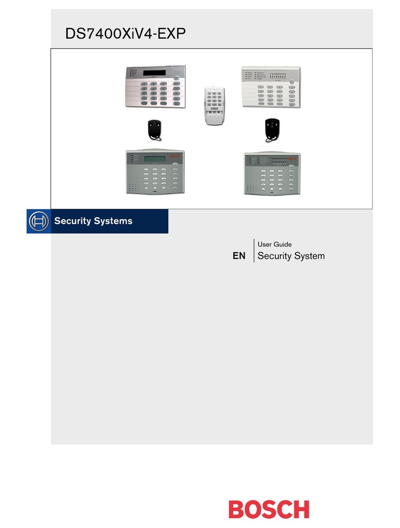
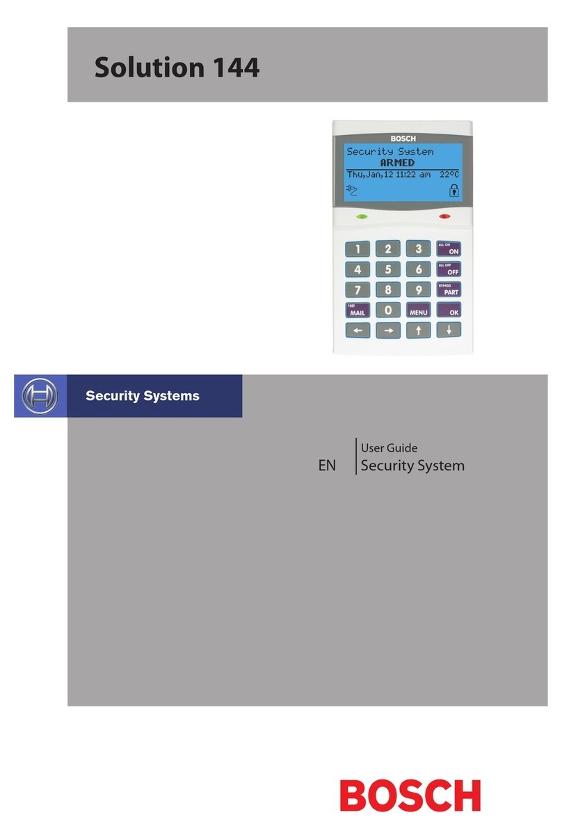
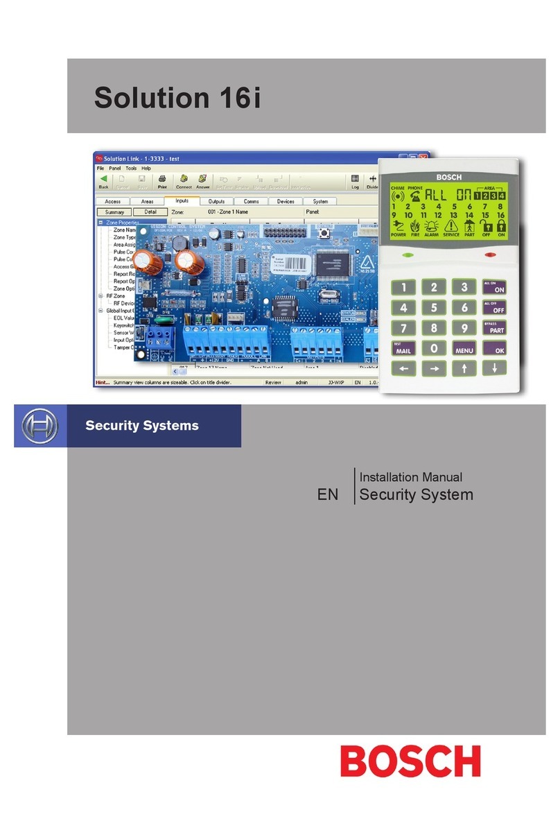
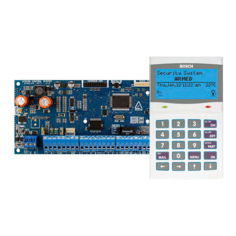
Bosch Solution 16i User manual

Solution 16i
Security System
Quick Start Guide
EN

2Bosch Security Systems 09/07 BLCC500R FTR1.02
Copyright © 2007 E&OE
Warnings
TELEPERMIT N12138
Intrusion Control Panel
N12138
M a d e I n
A u s t r a l i a
PTC 211 / 07 / 076
RN = 0.5
TELEPERMIT
This Bosch Solution 16i
CC500B Alarm System
may be connected to the
Telecom Network

3
Bosch Security Systems 09/07 BLCC500R FTR1.02 Copyright © 2007 E&OE

4Bosch Security Systems 09/07 BLCC500R FTR1.02
Copyright © 2007 E&OE

5
Bosch Security Systems 09/07 BLCC500R FTR1.02 Copyright © 2007 E&OE
i
For ease, it is recomended that the PCB mounting clips are installed from the rear of the enclosure before mounting it to the wall.
Figure 1: PCB and Mounting Clip Installation DiagramFigure 2: Tamper Bracket InstallationTable 1: Expansion Options

6Bosch Security Systems 09/07 BLCC500R FTR1.02
Copyright © 2007 E&OE
i
The supplied mounting clips are designed to use the 3mm machine screws supplied with the enclosure. The use of self tapping screws will damage the clips.
320 mm
260 mm
Figure 3: MW700 - Small Enclosure DetailsFigure 4: PCB Mounting Clip
Figure 5: MW700 Configuration Examples

7
Bosch Security Systems 09/07 BLCC500R FTR1.02 Copyright © 2007 E&OE
320 mm
520 mm
Figure 6: MW710 - Large Enclosure Details
Figure 7: MW710 Configuration Examples

8Bosch Security Systems 09/07 BLCC500R FTR1.02
Copyright © 2007 E&OE
i
For permanently connected equipment, a readily accessible disconnect device such as an A.C. Mains power outlet or mains switch shall be installed in a location near the equipment, for connection of the mains power cord.
TRANSFORMER
FUSE
220 - 240V A.C.
50 - 60Hz 24VA
8AG - 250V
250mA MAX
NEUTRAL
EARTH
ACTIVE
Figure 8: Internal Transformer Connection DiagramTable 2: Dialler Indicator LEDTable 3: Status Indicator LED
i
During factory defaulting the Status and Dialler LED indicators will flash alternatively for approximately 15 seconds.

9
Bosch Security Systems 09/07 BLCC500R FTR1.02 Copyright © 2007 E&OE
ZONE 2
N/C
N/C
ZONE 1
Figure 9: N/C No EOL Zone
ZONE 2
ZONE 1
N/C
N/C
ALARM
ALARM
Figure 10: N/C Single EOL Zone
(6K8 EOL)
(3K3 EOL)
N/C
N/C
ALARM
ALARM
ZONE 1
ZONE 9
Figure 11: N/C Split EOL Zone
1
2
TAMPER
(6K8 EOL)
TAMPER
(3K3 EOL)
N/C
N/C
ALARM ZONE 1
Figure 12: N/C Zone With Tamper
i
The Above diagrams display zone configurations using Normally-Closed Alarm contacts and Normally-Open Alarm Contacts. When using Normally-Open Alarm Contacts you must select Inverted Seal for each zone in MENU 3-1-8. A shorted loop is a tamper condition for all EOL zone configurations.
2
ZONE 2
N/O
N/O
ZONE 1
Figure 13: N/O No EOL Zone
ZONE 2
ZONE 1
N/O
N/O
ALARM
ALARM
Figure 14: N/O Single EOL Zone
(6K8 EOL)
(3K3 EOL)
N/O
N/O
ALARM
ALARM
ZONE 9
ZONE 1
Figure 15: N/O Split EOL Zone
TAMPER
(6K8 EOL)
TAMPER
(3K3 EOL)
N/C
N/O
ALARM ZONE 1
Figure 16: N/O Zone With Tamper
Orange
Blue
Red
Red
Orange
Grey
3K3
6K8
Brown (+/- 1%)
Brown (+/- 1%)
3K3 =
6K8 =
Orange
Blue
Figure 17: EOL Resistor Colour Chart

10 Bosch Security Systems 09/07 BLCC500R FTR1.02
Copyright © 2007 E&OE
ICON
Figure 18: Solution 16i Board Layout

11
Bosch Security Systems 09/07 BLCC500R FTR1.02 Copyright © 2007 E&OE
Premises
Telephone
Incoming Street
Telephone Line
+
-
GREEN
YELLOW
YELLOW
16-18V AC
24 VA
ZONE 2
ZONE 4
ZONE 1
ZONE 3
N/C
N/C
N/C
N/C
N/C
ZONE 6
ZONE 8
ZONE 5
ZONE 7
N/C
N/C
N/C
N/C
LAN B
LAN -
LAN A
LAN +
Keypad /
LAN Expansion
Device
Horn
Speaker
Strobe Light
+
-
12V DC
7.2AH Sealed
Lead Acid
Battery
Accessories
(e.g. PIR Detectors)
Siren Tamper Switch
Connect To
Cabinet Tamper
To Zone Terminals
+
NC
COM
-
-+
RJ12 6P4C - RJ12 6P4C
Phone Lead
Connect To
Telephone Line
Mode 3
Smoke
Detector
Piezo Siren
RF
Receiver
Connect To
Accessory
Power
GND
+12V
RF DATA
Earth Connection
Spade For Surge Protection
Panasonic
LC-P127R2P
or Equivalent
+
-
3K3
ICON
Figure 19: Solution 16i Connection Diagram

12 Bosch Security Systems 09/07 BLCC500R FTR1.02
Copyright © 2007 E&OE
i
It is recommended that one or more CM379 Isolators be used when connecting the LAN between multiple buildings.
Figure 20: LAN Connection Using 2 Pair Security Cable Recommended for LAN Lengths 300 metres or less.

13
Bosch Security Systems 09/07 BLCC500R FTR1.02 Copyright © 2007 E&OE
i
If a separate Communications Earth wire is installed, Do NOT connect the EARTH wire from any 3 wire plug pack to any modules EARTH input terminal.
i
The LAN must be terminated correctly for proper operation.
Figure 21: LAN Connection Using Twisted Pair Cable Recommended for LAN Lengths greater than 300 metres.

14 Bosch Security Systems 09/07 BLCC500R FTR1.02
Copyright © 2007 E&OE
Table 4: Terminal Block Descriptions
i
The maximum combined continuous current draw from the +12V, LAN + and COMM+ terminals must not exceed 1 AmpTable 5: Board Connector Descriptions

15
Bosch Security Systems 09/07 BLCC500R FTR1.02 Copyright © 2007 E&OE
↑↑↑ËÊÊÈÈÂTable 6: Keypad Emergency Alarm Trigger’sFigure 20: Keypad Emergency Alarm Trigger’s
i
Only 1 Keypad can be assigned to each address. All Keypads are supplied from the factory set to address 1. (OFF-OFF-OFF).
Figure 22: Keypad DIP Switch Address SettingsTable 7: Keypad DIP Switch Address Settings

16 Bosch Security Systems 09/07 BLCC500R FTR1.02
Copyright © 2007 E&OE
Figure 23: LCD Display Showing All ICONsIcon
AREA
POWER
FIRE
!
SERVICE
M
PART
OFF
ON
(
()
)
CHIME
PHONE
9 10
11 12
13 14
15 16
1 2
3 4
5 6
7
8
Fire
Alarm
Tone Burglary
Alarm
Tone Trouble
Tone Key Press
Tone Entry
Delay
Tone

17
Bosch Security Systems 09/07 BLCC500R FTR1.02 Copyright © 2007 E&OE
Exit
Delay
Tone Error
Tone Menu
Mode Chime
Tone 0#USER PIN#USER PIN#11#12#21#22###Table 8: DTMF Remote Control Functions2580#111#2580#2101#2580#272#
i
If the DTMF Quick Arm option is enabled then it is possible to remotely arm all areas without logging onto the panel. Simply enter 0 + # following the welcome jingle. Make sure that the phone being used to remotely control the panel is set to transmit DTMF tones when keys are pressed during the call. This option is disabled by default on some phones.

18 Bosch Security Systems 09/07 BLCC500R FTR1.02
Copyright © 2007 E&OE
i
When using the CM704B you should not select Split EOL monitoring. If you do the zones on the expander will not be available.Table 9: Zone Configuration Using Expanders
i
Currently the panel supports only supports CM704B zone expanders. The CM705 is not supported.Table 10: LAN Module Addressing

19
Bosch Security Systems 09/07 BLCC500R FTR1.02 Copyright © 2007 E&OE
i
All areas must be disarmed with no active alarms. To disarm all areas enter the Installer PIN and hold the Key for 2 seconds.
i
You can also select End from the menu and press to exit.Table 11: Keys Used During Programming
Figure 24: Text Characters Which Can Be Displayed.-bit-
123 56 8
Figure 25: Sample Option Bit Menu Display

20 Bosch Security Systems 09/07 BLCC500R FTR1.02
Copyright © 2007 E&OE
AreA 2
Figure 26: Area Text Programming DisplayTable 12: Text Keypad Character Set
i
The following additional special characters are available by scrolling using the up and down arrow keys. + - @ # $ “ & % * : ( ) / < > =974170
Figure 27: Telephone Number Programming Display Table 13: Phone Number ProgammingZn=3
Other manuals for Solution 16i
4
Table of contents
Other Bosch Security System manuals

Bosch
Bosch DB24C4200R2 User manual

Bosch
Bosch UEZ User manual

Bosch
Bosch AMAX panel 2100 User manual

Bosch
Bosch NDA-U-PA0 User manual

Bosch
Bosch ICP-VR8488 User manual

Bosch
Bosch Solution 16plus User manual

Bosch
Bosch ODU-FA Instruction Manual

Bosch
Bosch D222TD User manual

Bosch
Bosch DS937 User manual

Bosch
Bosch PVA-1EB User manual

Bosch
Bosch AMAX panel 4000 User manual

Bosch
Bosch ND 200 LSN User manual

Bosch
Bosch DIP-2040-00N User manual

Bosch
Bosch DIP-3040-00N User manual

Bosch
Bosch 2212 User manual

Bosch
Bosch LTC 5136/61 User manual

Bosch
Bosch SE 60 LSNi User manual
Bosch
Bosch HSG9483 Series User manual

Bosch
Bosch DS840LSN User manual

Bosch
Bosch RF1100 User manual