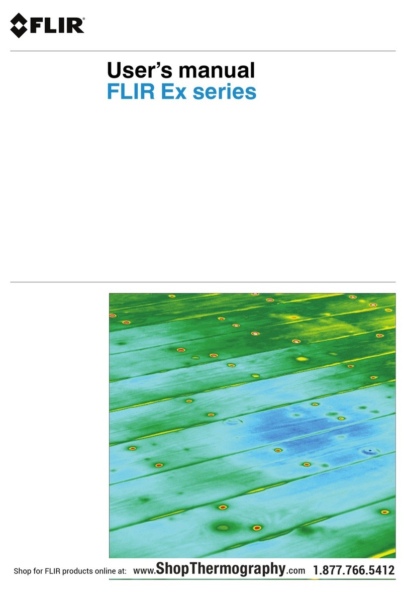
FLIR VS290-21 User manual

Quick Start
Thermal Videoscope Kits
Kit nos. VS290–21, VS290–32, VS290–33

Quick Start (en)
QUICK STEPS
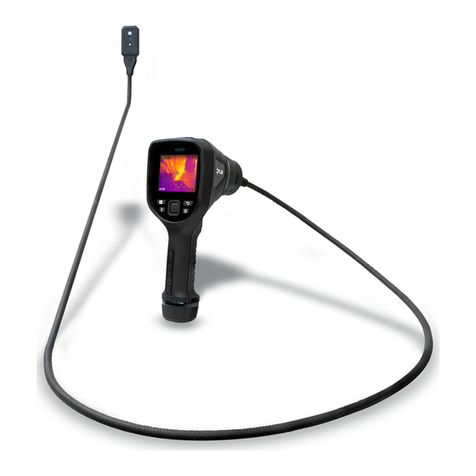
The Thermal Videoscope kit includes the VS290–00 base unit,
camera probe, and accessories (listed in Specifications section).
Before use, please read the entire Quick Start and online User
Manual, available at this address:
https://support.flir.com
1. Insert a fully charged battery into the VS290–00 handle.
2. Long press the power button to power up. If the battery voltage
is low, an alert will appear.
3. When powered, the VS290–00 displays a camera image and
function indicators.
4. Carefully position the probe into the area to be examined and
view the camera image.
5. Short press the worklight button to switch the light on/off.
6. To select an image mode, press the Menu button (centre), scroll
to the Image Mode icon using the navigation buttons (outer ring
of Menu button) and press Menu again. Use the navigation but-
tons to select Thermal MSX, Thermal, or Digital camera; press
Menu to confirm. The VSC-IR21 probe does not include MSX,
digital camera, or worklight.
7. Use the cross-hairs to target and measure the surface tempera-
ture of a spot. The measurement is shown digitally (upper left).
The thermal scale for the current image is shown on the right
edge of the display.
8. To capture an image or to stop/start a video, pull and hold the
trigger. Press the Gallery button to view stored images and vid-
eos. Images/videos can be transferred to a PC via USB.
2–10 EXTENDED WARRANTY
To activate the extended 2–10 warranty, please register your prod-
uct within 60 days of purchase. Otherwise, the standard one-year
warranty will be in effect from date of purchase. The 2–10 warranty
covers parts and labour for the camera for 2 years and coverage of
the detector for 10 years. Register your product at this address:
https://support.flir.com/prodreg
#NAS100055; r. AE/79702/79705; en-US 1
SAFETY INFORMATION
Safety Notes
• Before operating the device, you must read, understand, and fol-
low all instructions, dangers, warnings, cautions, and notes.
• FLIR Systems reserves the right to discontinue models, parts or
accessories, and other items, or to change specifications at any
time without prior notice.
WARNING
VS290–32 and VS290–33 are suitable for use in CAT IV 600 V environments.
VS290–21 is not intended for use in high voltage (> 600 V AC) environments.
WARNING
• Do not operate the device if you do not have the correct knowledge. Incor-
rect operation of the device can cause damage and injury to persons.
• Do not replace the batteries with the device powered up. This can cause
damage to the instrument and can cause injury to persons.
• Do not use the device if it show signs of damage. Injury to persons can
occur.
• Be careful working near voltages > 25 VAC or 35 VDC. There is a risk of
shock from these voltages. Injury to persons can occur.
• Do not touch expired/damaged batteries without gloves. Injury to persons
can occur.
• Do not cause a short circuit of the battery. This can cause damage to the
instrument and can cause injury to persons.
• Do not put batteries into a fire. Injury to persons can occur.
CHARGING THE BATTERY
This kit is supplied with two high capacity batteries and a stand-
alone two-bay charger. To charge batteries, place them in the
charger and plug it into an AC receptacle.
#NAS100055; r. AE/79702/79705; en-US 2

PRODUCT DESCRIPTIONS
VS290–00 Description
1. Camera display
2. Image and video Gallery button
3. LED worklight button
4. Menu button (center) and navigation buttons (outer ring)
5. Return button (exit a menu)
6. Power button (long press)
7. USB jack and memory card compartment
8. Collar screw locks probe to VS290–00
9. Probe connector
10. Probe
11. Image and video capture trigger
12. Handle grip
13. Battery compartment
#NAS100055; r. AE/79702/79705; en-US 3

Camera Probe Descriptions
1. Thermal camera lens
2. Digital camera lens
3. LED worklight
4. Probe
Display Description
1. Battery status
2. Wi-Fi (reserved for future use)
3. USB active
4. Worklight active
5. Cross-hairs. Target a surface spot (see Measurement Mode
menu)
6. Highest temperature sensed in the current camera image
#NAS100055; r. AE/79702/79705; en-US 4

7. Range of the selected display color palette. Alarm alerts are al-
so represented here
8. Lowest temperature sensed in the current camera image
9. Main menu icons
10. Thermal MSX alignment tool (VSC-IR32 and VSC-IR33). Refer
to the Alignment Distance menu
11. Temperature of targeted spot. In Hot/Cold Spot modes, this
area will show the MAX or MIN temperature
PROGRAMMING MENU
Basic Navigation
Press the Menu button to open the main menu and the sub-menus.
Use the navigation buttons to scroll left/right and up/down. Use the
Menu button to confirm a selection; press the Return button to exit
a menu.
Main Menu
The main menu options are: 1. Image Rotation, 2. Image Mode, 3.
Color, 4. Measurement, 5. Temperature Scale, and 6. Settings.
Image Rotation Menu
Press Menu on the Image Rotation icon and use the navigation
buttons to select 90° rotation or horizontal/vertical flip of the camera
image. Press Menu to confirm.
Image Mode Menu
Press Menu on the Image Mode icon and use the navigation
buttons to select: Digital, Thermal, Thermal MSX, or Alignment Dis-
tance. Thermal MSX (Multi-Spectral Dynamic Imaging) is an en-
hancement that improves image clarity by embossing visual scene
details on the thermal image. The MSX Alignment Distance option
allows you to fine tune the embossed visual scene details. The
VSC-IR21 does not include MSX or digital camera.
#NAS100055; r. AE/79702/79705; en-US 5

Color Palette Menu
To select a display color palette, press Menu on the Color icon
and use the navigation arrows to scroll. Press Menu when the de-
sired color palette is selected (Iron, Rainbow, Gray, Above Alarm,
or Below Alarm). In the Above/Below Alarm modes, select a high/
low alarm set point. An alert is displayed if an alarm is triggered.
Measurements Menu
Navigate to the Measurement icon and press Menu. Select
from the three options, detailed below, and then press Menu to
confirm.
• Centre Spot. Target a surface spot with the cross-hairs to meas-
ure its temperature. The measurement appears in the upper left
corner of the display (digitally).
• Hot/Cold Spot. Position the camera so that the rectangle display
target is covering an area of interest. The cross-hairs will move
to the hottest (MAX) or coldest (MIN) spot automatically (inside
the rectangle target). The MAX or MIN temperature is shown,
digitally, in the upper left corner.
• No Measurements. No radiometric temperature measurements
or cross-hair icons are displayed.
Temperature Scale Menu
Navigate to the Temperature Scale icon and press Menu. Use
the navigation buttons to select Auto (where the camera uses the
entire thermal range), or Lock (where you can freeze the range to a
narrow thermal region).
Settings Menu Overview
The settings menu has four sub-menus: Recording mode,
Measurement parameters, Save options, and Device settings. See
below.
#NAS100055; r. AE/79702/79705; en-US 6

SETTINGS MENU
Recording Mode Sub-Menu
Press Menu on the Settings icon and press Menu again at the Re-
cording Mode sub-menu. Select Video or Single-shot using the
navigation buttons and press Menu to confirm. Pull and hold the
trigger to start/stop a video recording or to capture a single image.
Measurement Parameters Sub-Menu
Press Menu on the Settings icon and press Menu again at the
Measurement Parameters sub-menu. Perform one or more of the
steps below:
• Scroll to the Emissivity option and press Menu. Select a preset
or choose a custom emissivity setting.
• Scroll to the Reflected Temperature option, press Menu, and set
a reflected temperature value.
• Scroll to the Atmospheric Temperature option, press Menu, and
set an atmospheric temperature value.
Save Options Sub-Menu
Press Menu on the Settings icon and press Menu again at the Save
Options sub-menu. When set to ON, the camera stores two images
(thermal and digital) for each Thermal MSX image captured. Use
the navigation buttons to set on/off and press Menu to confirm.
Device Settings Sub-Menu
Press Menu on the Settings icon and press Menu again at the De-
vice Settings sub-menu to begin programming or viewing the fol-
lowing items. Before contacting customer support, please note the
serial number for the probe and the VS290–00 in this sub-menu.
• Set the Language, Time/Date, and Units of measure.
• Set individual Auto Power Off (APO) timers for the camera and
the worklight.
• Configure or disable Wi-Fi (reserved for future use).
• Adjust the screen and worklight brightness.
• View system information including serial number and firmware
version.
• Revert to factory default conditions and format memory card.
• View regulatory data.
#NAS100055; r. AE/79702/79705; en-US 7

WORKING WITH IMAGES AND VIDEO
Capturing Images and Video
To select video or single-shot mode see the Recording Mode sub-
menu section.
Pull and hold the trigger to capture an image or to start recording
video. For images, release the trigger when the filename appears.
For video, release the trigger when the video timer starts. Pull and
hold trigger to stop the video recording.
Images and videos are stored on the memory card (supplied) in-
serted in the VS290–00 top compartment. Do not insert or remove
the memory card while the VS290–00 is powered.
Viewing Images and Video
Press the Gallery button to open the image/video gallery. Scroll to
an image/video and press Menu to open it. Press Menu again at an
opened image/video to access these options: Play (video only), full
screen mode, image/video information, and image/video delete.
Transferring Images and Video
Transfer to a PC by first connecting the VS290–00 to a PC using the
supplied USB cable (the USB jack is located in the VS290–00 top
compartment), and then use the VS290–00 as you would a typical
external storage drive.
#NAS100055; r. AE/79702/79705; en-US 8

SPECIFICATIONS
For additional specifications see the on-line user manual.
IMAGING AND OPTICAL SPECIFICATIONS
IR Resolution 160 x 120 pixels
Field of View (FOV) 57° x 44°
Minimum focus distance 5.9 in. (0.15 m); 25.6 in. (0.65 m) in MSX
mode
Image frequency 8.7 Hz
IMAGE PRESENTATION
Display resolution 320 x 240 pixels
Screen size 3.5 in. (8.9 cm)
Color palettes Iron, Rainbow, Gray, Below/Above Alarm
Image modes IR, Visual, and MSX (VSC-IR21 is IR-only)
MEASUREMENT AND ANALYSIS
Object temperature range 14 ℉to 752 ℉(-10 ℃to 400 ℃)
Measurement accuracy At ambient temperature. 59 to 95 ℉(15 to 35
℃) and object temp. above 32 ℉(0 ℃)
32 to 212 ℉(0 to 100 ℃): ±5.5 ℉(±3 ℃)
212 to 752 ℉(100 to 400 ℃): ±3%
Spotmeter Centre spot, hot spot, cold spot
Emissivity correction 3 presets and 1 custom setting
IMAGE STORAGE AND VISUAL (DIGITAL) CAMERA
Storage capacity Removable SD Card (16 GB)
Image/Video file formats Image: Radiometric .jpg; Video: .mpeg-4
Digital camera resolution 2 MP (VSC-IR21 does not include digital
camera)
Field of View (FOV) 83°
#NAS100055; r. AE/79702/79705; en-US 9

DATA COMMUNICATION
USB USB Type-C
BATTERY
Battery type Lithium ion
Battery operating time > 5 hours (full display brightness and work-
light ON)
INCLUDED EQUIPMENT AND ACCESSORIES
Videoscope display, camera probe, rechargeable batteries (2), battery charg-
er, SD card, USB cable, wrist strap, hard case, printed documentation, and
complimentary one–year subscription for FLIR Thermal Studio Standard
application.
CUSTOMER SUPPORT
Customer Support Telephone List https://support.flir.com/contact
Repair, Calibration, and Technical Support https://support.flir.com
#NAS100055; r. AE/79702/79705; en-US 10

#NAS100055; r. AE/79702/79705; en-US 11


last page
Publ. No.: NAS100055
Release: AE
Commit: 79702
Head: 79705
Language: en-US
Modified: 2021-09-24
Formatted: 2021-09-24
Website
http://www.flir.com
Customer support
http://support.flir.com
Copyright
© 2021, FLIR Systems, Inc. All rights reserved worldwide.
Disclaimer
Specifications subject to change without further notice. Models and accessories
subject to regional market considerations. License procedures may apply.
Products described herein may be subject to US Export Regulations. Please
Quick Start
This manual suits for next models
2
Table of contents
Other FLIR Thermal Camera manuals
Popular Thermal Camera manuals by other brands

PeakTech
PeakTech 5610 Operation manual

Chauvin Arnoux
Chauvin Arnoux C.A 1954 DiaCAm 2 quick start guide

Satir
Satir UMTI user manual

International Safety Instruments
International Safety Instruments Surveyor Owner's operation manual

Hikmicro
Hikmicro HM-TS03-15XF quick start guide

TESTO
TESTO 870 instruction manual