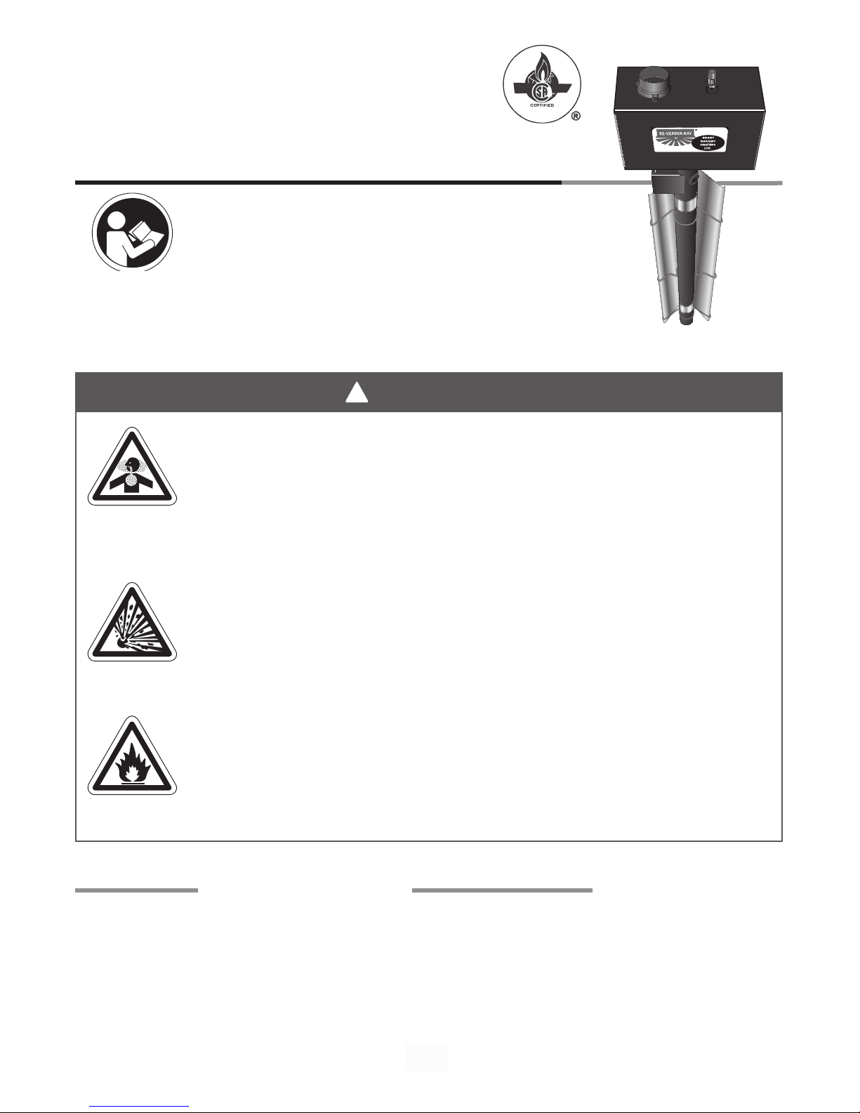
Brant Radiant Heaters HL2 Series User manual

!
WARNING
For Your Safety
If you smell gas:
• Open windows.
• Do not touch electrical switches.
• Extinguish any open flame.
• Immediately call your gas supplier from a
neighbours phone.
• Do not try to light any appliances.
Not for residential use! This heater is NOT approved for use in any residential application.
This includes, but is not limited to, attached garages, solariums, living quarters, etc.
Installation in residential spaces may result in property damage, asphyxiation, serious injury
or death. Consult your local fire marshall and/or insurance carrier if unsure of your
application.
Interdit pour usage résidentiel. Ne pas utiliser cet appareil à la maison, dan les chambres
à coucher, dan les harages attenants, etc.
This is NOT an explosion proof heater. Where there is a possibility of exposure to flammable
vapors, consult the local fire marshall, the fire insurance carrier and other authorities for
approval of proposed installation.
Cet émetteur n’est pas un appareil antideflagrant. Lorsqu’il y a risque de contact avec des
vapeurs inflammables, consulter le commissaire local des incendies, la compagnie
d’assurance incendie ou tout autre authorité compétente pour approbation de l’installation.
Storage of gasoline or other flammable vapors and liquids in the vicinity of this or any other
appliance may result in fire or explosion. Do not store or use gasoline or other flammable
vapors and liquids in the vicinity of this or any other appliance. Always maintain published
clearance to combustibles.
Il est interdit d’utiliser des liquides inflammables ou degagent des vapeors inflammabled a
proximaite de tout appareil fonctionnant au gaz.
Brant Radiant Heaters, Ltd.
Form#: LIOBRHL2 3/12
HL2 Series
Gas-Fired Infrared Tube Heater
Consignes De Sécurité
Si vous sentez une odeur de gaz:
• Ouvrez les fenêtres.
• Ne touches pas aux interrupters électriques.
• Éteignez toute flamme nue.
• Contactez immediatement votre compagnie de gaz.
WARNING: Improper installation, adjustment, alteration, service or
maintenance can cause property damage, injury or death. Read the
installation, operating and maintence instructions thoroughly before
installing or servicing this equipment.
AVERTISSEMENT. Une installation, un réglage, une modification, une
réparation ou un entretien incorrect peut entraîner des dommages matériel,
des blessures ou la mort. lisez attentivement les instructions d’installation, de
fonctionnement et d’entretien avant de procéder à l’installation ou à l’entretien
de cet équipement.
Keep these instructions for future reference.

2
HL2 Series
Contents
1.0 Introduction .....................................................................3
Overview . . . . . . . . . . . . . . . . . . . . . . . . . . . . . . . . . . . . . . . . . . . . . . . . . . . . . . . . . . . . . . . . . . 3
Heater Components..........................................................3
Product Specifications........................................................4
2.0 Safety ..........................................................................5
Warning Symbols............................................................5
Applications................................................................5
Standards, Certifications and Government Regulations. . . . . . . . . . . . . . . . . . . . . . . . . . . . . . 6
Safety Labels and Locations...................................................7
Clearance to Combustibles....................................................9
3.0 Installation ......................................................................11
Design Considerations and Prechecks...........................................11
Recommended Mounting Heights and Coverages . . . . . . . . . . . . . . . . . . . . . . . . . . . . . . . . . . 13
Hanger Placement and Suspension ......................................................14
Radiant Tube Assembly.......................................................18
Optional Elbow or U-Bend Accessory Configuration . . . . . . . . . . . . . . . . . . . . . . . . . . . . . . . . 19
Burner Control Box Suspension . . . . . . . . . . . . . . . . . . . . . . . . . . . . . . . . . . . . . . . . . . . . . . . . 21
Reflector Assembly . . . . . . . . . . . . . . . . . . . . . . . . . . . . . . . . . . . . . . . . . . . . . . . . . . . . . . . . . . 22
Baffle Assembly and Placement . . . . . . . . . . . . . . . . . . . . . . . . . . . . . . . . . . . . . . . . . . . . . . . . 24
Final Heater Assembly .......................................................25
Venting ...................................................................26
Sidewall (Horizontal) Venting...................................................27
Roof (Vertical) Venting........................................................28
Optional Unvented Operation . . . . . . . . . . . . . . . . . . . . . . . . . . . . . . . . . . . . . . . . . . . . . . . . . . 30
Combustion Air Requirements . . . . . . . . . . . . . . . . . . . . . . . . . . . . . . . . . . . . . . . . . . . . . . . . . 30
Gas Supply . . . . . . . . . . . . . . . . . . . . . . . . . . . . . . . . . . . . . . . . . . . . . . . . . . . . . . . . . . . . . . . . 32
Allowances for Expansion.....................................................36
Electrical Requirements.......................................................37
Wiring.....................................................................38
4.0 Operation . . . . . . . . . . . . . . . . . . . . . . . . . . . . . . . . . . . . . . . . . . . . . . . . . . . . . . . . . . . . . . . . . . . . . . . 41
Operating Instructions . . . . . . . . . . . . . . . . . . . . . . . . . . . . . . . . . . . . . . . . . . . . . . . . . . . . . . . . 41
Sequence of Operation .......................................................41
Thermostat . . . . . . . . . . . . . . . . . . . . . . . . . . . . . . . . . . . . . . . . . . . . . . . . . . . . . . . . . . . . . . . . 41
Operational Indicator Lights....................................................42
Diagnostics . . . . . . . . . . . . . . . . . . . . . . . . . . . . . . . . . . . . . . . . . . . . . . . . . . . . . . . . . . . . . . . . 43
5.0 Troubleshooting Guide............................................................44
6.0 Maintenance . . . . . . . . . . . . . . . . . . . . . . . . . . . . . . . . . . . . . . . . . . . . . . . . . . . . . . . . . . . . . . . . . . . . 48
Routine Inspection...........................................................48
Heater Components and Parts List..............................................50
7.0 Limited Warranty . . . . . . . . . . . . . . . . . . . . . . . . . . . . . . . . . . . . . . . . . . . . . . . . . . . . . . . . . . . . . . . . . 52
8.0 Kit Contents Check List ...........................................................54

3
HL2 Series
1.0 Introduction
Tube Hanger
Reflector
Reflector Center Support
10’ Primary/
Secondary
Combustion
Chamber(s)
Baffles
Reflector End Cap with Clips*
Tube Clamp
Burner Control Box
Flexible Type 1 Rubber Hose*
Radiant
Tube(s)
Figure 1.1 • Heater Components *
Igniter/Sensor Box
Chains are not provided in kit.
Optional accessory. P/N: THCS
16” Burner Tube
* Not all items illustrated may be provided with your heater.
Refer to kit contents on page 52 of the Series Manual.
Tube Hanger
Reflector
Tension
Spring*
Overview
The intent of this manual is to provide information regarding general safety, installation, operation and maintenance
of the tube heater. You must read, and understand, the instructions and safety warnings in this manual before
installing the tube heater. Additional literature on this and other products is available
at www.brantradiant.com.
Heater Components
Prior to installation, verify that the heater’s gas type and voltage (as listed on the rating plate) match that of your
application. Also verify that you have received all heater contents included with your tube heater. Reference page
52 for a list of the kit contents for your model heater. Materials not included in the heater kit contents (e.g., screws,
vent material, terminals, etc.) are the responsibility of the installer. Notify your product representative or Brant
Radiant Heaters Ltd. of any discrepancy or missing kit contents prior to installing unit.
1.0 Introduction • Overview • Heater Components

4
HL2 Series
Model
Number
Gas Type
(select one)
BTU/H
(High Fire)
BTU/H
(Low Fire)
Straight Length
U-Tube Length
Standard
Weight (lbs.)
Stainless Steel Weight
(lbs.)
Recommended
Mounting Height
Combustion Chamber
(Black Coated)
Radiant Emitter Tube(s)
(Black Coated)
Radiant Surface Area
(sq. ft.)
36” Baffle Sections
HL2-20-65 N or LP 65,000 50,000 21’-7” 13’-0” 120 N/A 9’ to 14’ Alum Alum 20.2 5
HL2-20-75 N or LP 75,000 50,000 21’-7” 13’-0” 120 145 10’ to 15’ Alum Alum 20.2 5
HL2-20-96 N or LP 96,000 65,000 21’-7” 13’-0” 120 N/A 11’ to 18’ Alum Alum 20.2 5
HL2-30-65 N or LP 65,000 50,000 31’-3” **17’-8” 160 N/A 10’ to 15’ Alum Alum 30.4 4
HL2-30-75 N or LP 75,000 50,000 31’-3” **17’-8” 160 195 11’ to 18’ Alum Alum 30.4 4
HL2-30-100 N or LP 100,000 65,000 31’-3” **17’-8” 160 195 12’ to 20’ Alum Alum 30.4 5
HL2-30-125 N or LP 125,000 95,000 31’-3” **17’-8” 160 N/A 13’ to 23’ Alum Alum 30.4 5
HL2-40-65 N or LP 65,000 50,000 40’-11” 22’-8” 190 N/A 11’ to 18’ Alum Alum 40.5 2
HL2-40-75 N or LP 75,000 50,000 40’-11” 22’-8” 190 235 11’ to 18’ Alum Alum 40.5 2
HL2-40-100 N or LP 100,000 65,000 40’-11” 22’-8” 190 235 12’ to 20’ Alum Alum 40.5 4
HL2-40-125 N or LP 125,000 95,000 40’-11” 22’-8” 190 235 13’ to 23’ Alum Alum 40.5 4
HL2-40-150 N or LP 150,000 100,000 40’-11” 22’-8” 190 235 14’ to 25’ Titan Alum 40.5 4
HL2-40-175 N or LP * 175,000 125,000 40’-11” 22’-8” 190 N/A 15’ to 27’ Titan Alum 40.5 4
HL2-50-125 N or LP 125,000 95,000 50’-7” **27’-4” 235 290 15’ to 27’ Alum Alum 50.6 4
HL2-50-150 N or LP 150,000 100,000 50’-7” **27’-4” 235 290 15’ to 27’ Titan Alum 50.6 4
HL2-50-175 N or LP * 175,000 125,000 50’-7” **27’-4” 235 N/A 16’ to 30’ Titan Alum 50.6 2
HL2-50-200 N or LP * 200,000 145,000 50’-7” **27’-4” 235 N/A 17’ to 35’ Titan Alum 50.6 2
HL2-60-150 N or LP 150,000 100,000 60’-3” 32’-4” 265 330 16’ to 30’ Titan Alum 60.7 2
HL2-60-175 N orLP * 175,000 125,000 60’-3” 32’-4” 265 N/A 16’ to 30’ Titan Alum 60.7 2
HL2-60-200 N or LP * 200,000 145,000 60’-3” 32’-4” 265 N/A 17’ to 35’ Titan Alum 60.7 2
HL2-70-175 N or LP * 175,000 125,000 69’-11” **37’-2” 300 N/A 19’ to 42’ Titan Alum 70.9 2
HL2-70-200 N or LP * 200,000 145,000 69’-11” **37’-2” 300 N/A 19’ to 42’ Titan Alum 70.9 2
* Model requires stainless steel tube clamp (P/N: TP-220) to be located at the seam between the primary combustion
chamber and the secondary combustion tube downstream of the burner control box.
** Model requires 5EA-SUB accessory package when installing in a ‘U’ configuration (P/N: TF1B).
Titan = Black coated titanium stabilized aluminized steel.
Alum = Black coated aluminized treated steel.
Product Specifications
Chart 1.2 • HL2 Series Specifications
1.0 Introduction • Product Specifications

5
HL2 Series
2.0 Safety
Warning indicates a potentially hazardous situation
which, if not avoided, could result in death or injury.
Caution indicates a potentially hazardous situation
which, if not avoided, could result in minor or
moderate injury.
Notice indicates a potentially hazardous situation
which, if not avoided, could result in property
damage.
NOTICE
WARNING
!
!
CAUTION
!
WARNING
!
!
WARNING
!
!
Warning Symbols
Safety is the most important consideration during installation, operation and maintenance of the tube
heater. You will see the following symbols and signal words when there is a hazard related to safety or
property damage.
Improper installation, adjustment, alteration, service or maintenance can cause
property damage, serious injury or death. Read and understand, the installation,
operating and maintenance instructions thoroughly before installing or servicing this
equipment. Only trained, qualified gas installation and service personnel may install or
service this equipment.
Applications
This is not an explosion proof heater. No tube heater may be used in a Class 1 or Class 2 Explosive
Environment. Consult your local fire Marshall, insurance carrier and other authorities for approval if the
proposed installation is in question.
Commercial / Industrial
Unless otherwise indicated, tube heaters are designed and certified for use in industrial and commercial
buildings, such as warehouses, manufacturing plants, aircraft hangars and vehicle maintenance shops.
For maximum safety the building must be evaluated for potential problems before installing the heating
system. A critical safety factor to consider before installation is the clearance to combustibles.
Not For Residential Use. Installation of a commercial tube heater system in residential indoor spaces
may result in property damage, serious injury or death.
2.0 Safety • Warning Symbols • Applications

6
HL2 Series
Building
Type
Installation of this tube heater in public garages must conform to the following codes:
United States: Standard for Parking Structures NFPA 88A (latest edition) or the
Code for Motor Fuel Dispensing Facilities and Repair Garages NFPA 30A (latest
edition).
Canada: Refer to CAN/CGA B149.1 and B149.2: Installation Codes for Gas
Burning Appliances and applicable Standards for Public Garages.
Guidelines:
• Heaters must not be installed less than 8 ft. (2.4 m) above the floor. Minimum
clearances to combustibles must be maintained from vehicles parked below the
heater.
• When installed over hoists, minimum clearances to combustibles must be maintained
from the upper most point of objects on the hoist.
Installation of this tube heater in aircraft hangars must be in accordance with the
following codes:
United States: Refer to Standard for Aircraft Hangars, ANSI/NFPA 409
(latest edition).
In Canada: Refer to Standard CAN/CGA B149.1 and B149.2 and applicable
Standards for Aircraft Hangars.
Guidelines:
• In areas adjoining the aircraft storage area (e.g., shops, offices) the bottom of heaters
shall be installed no less than 8 ft. (2.4 m) above the floor.
• Suspended or elevated heaters shall be located in spaces where they shall not be
subject to damage by aircraft, cranes, movable scaffolding or other objects.
Provisions shall be made to assure accessibility to suspended tube heaters for recurrent
maintenance purposes.
Standards, Certifications and Government Regulations
Installation of this tube heater must comply with all applicable local, state and national specifications,
regulations and building codes. Contact the local building inspector and/or fire marshall for guidance.
In the absence of local codes, the installation must conform to the latest edition of:
United States: National Fuel Gas Code, ANSI Z223.1 (NFPA 54).
Canada: CAN/CGA B149.1 and .2, Canadian Electrical Code C22.1
Public
Garages
Aircraft
Hangars
Chart 2.1 • Standards and Code Installation Guidelines • Building Type
Codes and Guidelines
2.0 Safety • Standards, Certifications and Government Regulations

7
HL2 Series
CLEARANCESTO COMBUSTIBLES IN. & CM / DÉGAGEMENTSAUXMATIÈRES COMBUSTIBLES PCE & CM
SAFETY INFORMATION / INFORMATIONS DE SÉCURITÉ
FAILURETO COMPLY WITH THE STATED
CLEARANCESTO COMBUSTIBLES
COULDRESULT IN PROPERTY DAMAGE,
PERSONALINJURY AND/OR DEATH.
LEDÉFAUT DE SE CONFORMER AUX DONNÉES DES
DÉGAGEMENTSAUX MATIÈRES INFLAMMABLES
PEUTRÉSULTER EN BLESSURES PERSONNELLES
ET/OUDOMMAGES SUR LA PROPRIÉTÉ.
WARNING AVERTISSEMENT
CAUTION:KEEP COVER IN PLACE. REMOVE FOR SERVICE ONLY.
ATTENTION:GARDER LE COUVERCLE EN PLACE. N’ENLEVER QUE POUR L’ENTRETIEN
TOP
FRONT BEHIND
BELOW
45°MOUNTING ANGLE
SIDE
SIDE
TOP
BELOW
0°W/2 SIDE SHIELDS
TOP
SIDE
BELOW
0°W/1 SIDE SHIELD
TOCEILING
BR-VCF
12 IN.or 30.5 cm
CLEARANCE
TOWALLOR
COMBUSTIBLES
20ft or 6.1m
DOWNSTREAM
&BEYOND
FIRST20 ft
or6.1 m
BURNER
MIN.12IN.or 30.5 cm
ENDCLEARANCE
TOP
SIDE SIDE
0°MOUNTING ANGLE
SIDE
BELOW
47
47
47
47
47
47
47
47
60
60
60
60
66
66
66
66
76
76
76
76
30
81
81
81
81
92
92
92
92
94
94
94
94
44
6
10
6
6
6
10
6
6
6
10
6
6
6
10
6
6
6
10
6
6
6
6
10
6
6
6
10
6
6
6
10
6
6
6
9
8
8
9
9
8
8
9
9
8
8
9
14
8
8
16
20
8
8
20
7
24
8
8
23
34
8
8
30
41
8
8
30
11
9
39
29
9
9
39
29
9
9
39
29
9
14
39
29
16
20
58
42
20
7
24
58
42
23
34
63
50
30
41
63
54
30
11
DX,AG1, SE -
50,000N or P
W/1SIDE SHIELD
W/2SIDE SHIELDS
DX,AG1, SE -
60,000N or P
W/1SIDE SHIELD
W/2SIDE SHIELDS
DX,HL, SE, ST,AG1, AG2 -
75,000 N or P
W/1SIDE SHIELD
W/2SIDE SHIELDS
DX,HL, SE, ST,AG1, AG2 -
100,000N or P
W/1SIDE SHIELD
W/2SIDE SHIELDS
DX,HL, SE, ST,AG1, AG2 -
125,000N or P
W/1SIDE SHIELD
W/2SIDE SHIELD
20ft or 6.1 m
DOWNSTREAM
OFBURNER
DX,HL, SE, ST,AG1, AG2 -
150,000N or P
W/1SIDE SHIELD
W/2SIDE SHIELDS
DX,HL, SE, ST -
175,000N or P
W/1SIDE SHIELD
W/2SIDE SHIELDS
DX,HL, SE, ST -
200,000N or P
W/1SIDE SHIELD
W/2SIDE SHIELDS
20ft or 6.1 m
DOWNSTREAM
OFBURNER
0°
45°
0°
0°
0°
45°
0°
0°
0°
45°
0°
0°
0°
45°
0°
0°
0°
45°
0°
0°
0°
0°
45°
0°
0°
0°
45°
0°
0°
0°
45°
0°
0°
0°
22.9
20.3
20.3
22.9
22.9
20.3
20.3
22.9
22.9
20.3
20.3
22.9
35.6
20.3
20.3
40.6
50.8
20.3
20.3
50.8
17.8
61
20.3
20.3
58.4
86.4
20.3
20.3
76.2
104.1
20.3
20.3
76.2
27.9
22.9
99.1
73.7
22.9
22.9
99.1
73.7
22.9
22.9
99.1
73.7
22.9
35.6
99.1
73.7
40.6
50.8
147.3
106.7
50.8
17.8
61
147.3
106.7
58.4
86.4
160
127
76.2
104.1
160
137.2
76.2
27.9
15.2
25.4
15.2
15.2
15.2
25.4
15.2
15.2
15.2
25.4
15.2
15.2
15.2
25.4
15.2
15.2
15.2
25.4
15.2
15.2
15.2
15.2
25.4
15.2
15.2
15.2
25.4
15.2
15.2
15.2
25.4
15.2
15.2
15.2
119.4
119.4
119.4
119.4
119.4
119.4
119.4
119.4
152.4
152.4
152.4
152.4
167.6
167.6
167.6
167.6
193
193
193
193
76.2
205.7
205.7
205.7
205.7
233.7
233.7
233.7
233.7
238.8
238.8
238.8
238.8
111.8
ANGLEDE
MONTAGE
ARRIÈRE AVANT
DESSUS
DESSOUS
CÔTE
MODÈLES
MOUNTING
ANGLE
BEHIND INFRONT
TOP
BELOW
SIDE
MODELNO.
UNITS DEGREES
IN.
PCE CM
IN.
PCE CM
IN.
PCE CM
IN.
PCE CM
MODEL /MODELE NO. INPUT BTU/H FOR USE WITH
NATURAL GAS
RADIATEUR A INFRAROUGE A FAIBLE INTENSITE
VOLTS A.C.
STARTING AMPS.
RUNNING AMPS.
120~60Hz
4.8
1.1
MANIFOLD PRESSURE
MIN. INLET PRESSURE
ORIFICE SIZE
3.5” WC
5.0” WC
#3 D.M.S
HEATER TYPE
VERSION
MIN. MOUNTING ANGLE:
COMBUSTION CHAMBER:
4” BC ALUMINUM
FOR INDOOR USE
BRANT RADIANT HEATERS LIMITED
34 SCOTT AVE., PARIS, ONTARIO
TEL: 1-519-442-7823 WWW.BRANTRADIANT.COM
ANSI Z83.20b - 2011 CSA 2.32b - 2011 Low - Intensity Infrared Htr.
ANS Z83.20b - 2011 CSA - 2011 Low - Intensity Infrared Htr.
SERIAL NO.
0870 XXXX XXXX 0001
RE-VERBER-RAY LOW INTENSITY INFRARED HEATER
FOR INDOOR INSTALLATION ONLY. NOT FOR USE IN RESIDENTIAL DWELLING.
INSTALLATION À L’EXTÉRIEUR SEULEMENT. NE PAS INSTALLER DANS UN LOGEMENT.
MAX. MOUNTING ANGLE:
0 DEGREES
45 DEGREES
FOR STAINLESS STEEL UPGRADES THE
COMBUSTION TUBE IS UPGRADED TO 409
STAINLESS STEEL.
C1
10/11
HL2-40-125N 125,000/95,000
SAMPLE
MODEL /MODELE NO. INPUT BTU/H FOR USE WITH
NATURAL GAS
RADIATEUR A INFRAROUGE A FAIBLE INTENSITE
VOLTS A.C.
STARTING AMPS.
RUNNING AMPS.
120~60Hz
4.8
1.1
MANIFOLD PRESSURE
MIN. INLET PRESSURE
ORIFICE SIZE
3.5” WC
5.0” WC
#3 D.M.S
HEATER TYPE
VERSION
MIN. MOUNTING ANGLE:
COMBUSTION CHAMBER:
4” BC ALUMINUM
FOR INDOOR USE
BRANT RADIANT HEATERS LIMITED
34 SCOTT AVE., PARIS, ONTARIO
TEL: 1-519-442-7823 WWW.BRANTRADIANT.COM
ANSI Z83.20b - 2011 CSA 2.32b - 2011 Low - Intensity Infrared Htr.
ANS Z83.20b - 2011 CSA - 2011 Low - Intensity Infrared Htr.
SERIAL NO.
0870 XXXX XXXX 0001
RE-VERBER-RAY LOW INTENSITY INFRARED HEATER
FOR INDOOR INSTALLATION ONLY. NOT FOR USE IN RESIDENTIAL DWELLING.
INSTALLATION À L’EXTÉRIEUR SEULEMENT. NE PAS INSTALLER DANS UN LOGEMENT.
MAX. MOUNTING ANGLE:
0 DEGREES
45 DEGREES
FOR STAINLESS STEEL UPGRADES THE
COMBUSTION TUBE IS UPGRADED TO 409
STAINLESS STEEL.
C1
10/11
HL2-40-125N 125,000/95,000
Air Metering Orifice
DO NOT REMOVE
TP-114
TP-3014 1 - 1/2"
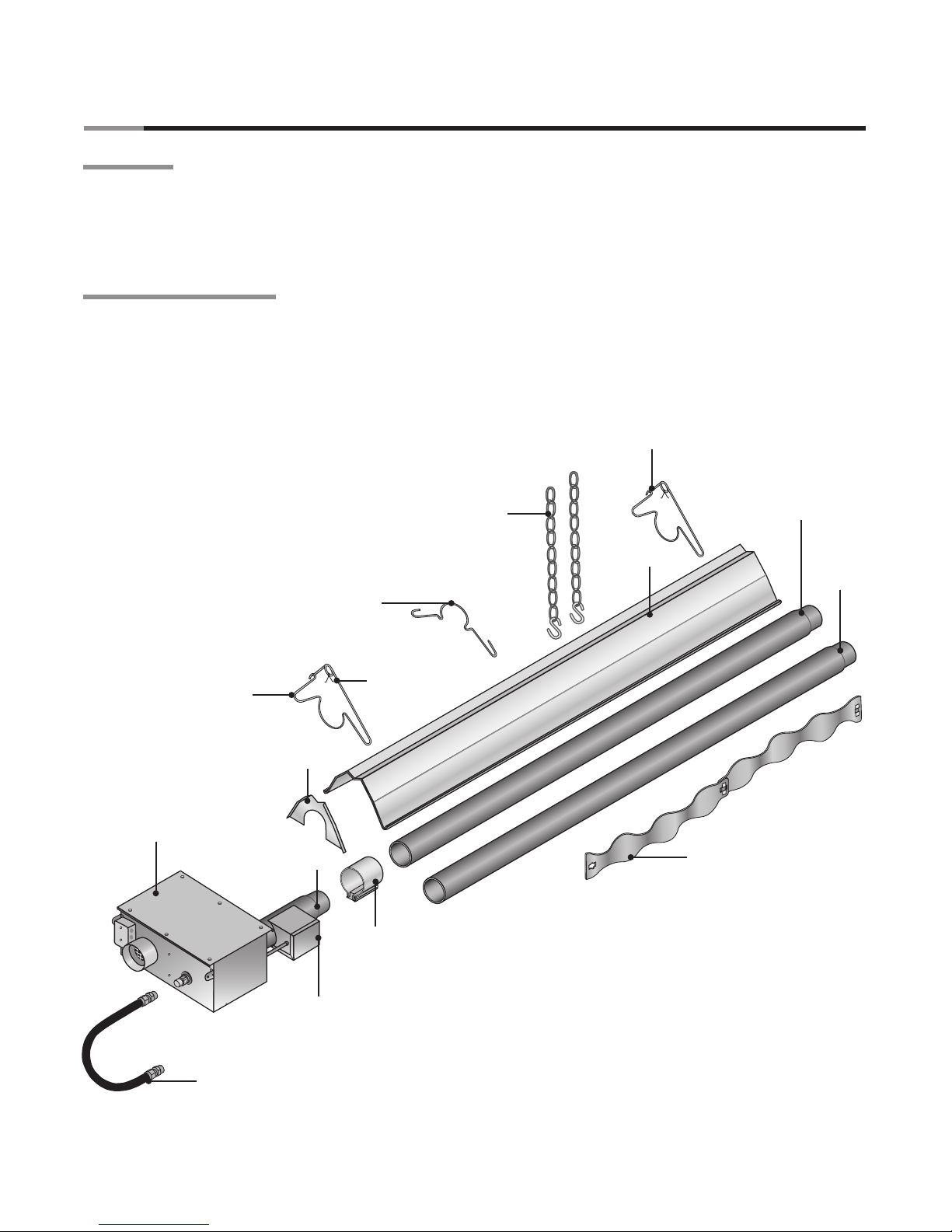
Safety Labels and Their Locations
Back Panel
Top Panel
Bottom Panel
Rating
Plate
Clearance to Combustibles
Label.
F/N: LLLOGO1
Product safety signs or labels should be replaced by the product user when they no longer are legible.
Contact either your local distributor or the product manufacturer for obtaining replacement signs or labels.
F/N: LLAC
Air Metering Orifice
SAMPLE
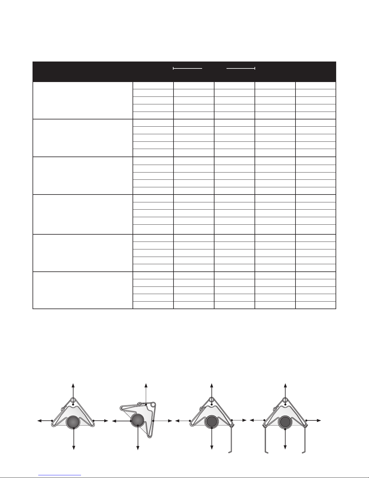
CLEARANCES TO COMBUSTIBLES IN. & CM / DÉGAGEMENTS AUX MATIÈRES COMBUSTIBLES PCE & CM
SAFETY INFORMATION / INFORMATIONS DE SÉCURITÉ
FAILURE TO COMPLY WITH THE STATED
CLEARANCES TO COMBUSTIBLES
COULD RESULT IN PROPERTY DAMAGE,
PERSONAL INJURY AND/OR DEATH.
LE DÉFAUT DE SE CONFORMER AUX DONNÉES DES
DÉGAGEMENTS AUX MATIÈRES INFLAMMABLES
PEUT RÉSULTER EN BLESSURES PERSONNELLES
ET/OU DOMMAGES SUR LA PROPRIÉTÉ.
WARNING AVERTISSEMENT
CAUTION: KEEP COVER IN PLACE. REMOVE FOR SERVICE ONLY.
ATTENTION: GARDER LE COUVERCLE EN PLACE. N’ENLEVER QUE POUR L’ENTRETIEN
TOP
FRONT BEHIND
BELOW
45° MOUNTING ANGLE
SIDE
SIDE
TOP
BELOW
0° W/2 SIDE SHIELDS
TOP
SIDE
BELOW
0° W/1 SIDE SHIELD
TO CEILING
BR-VCF
12 IN.or 30.5 cm
CLEARANCE
TO WALL OR
COMBUSTIBLES
20 ft or 6.1 m
DOWNSTREAM
& BEYOND
FIRST 20 ft
or 6.1 m
BURNER
MIN. 12 IN.or30.5 cm
END CLEARANCE
TOP
SIDE SIDE
0° MOUNTING ANGLE
SIDE
BELOW
47
47
47
47
47
47
47
47
60
60
60
60
66
66
66
66
76
76
76
76
30
81
81
81
81
92
92
92
92
94
94
94
94
44
6
10
6
6
6
10
6
6
6
10
6
6
6
10
6
6
6
10
6
6
6
6
10
6
6
6
10
6
6
6
10
6
6
6
9
8
8
9
9
8
8
9
9
8
8
9
14
8
8
16
20
8
8
20
7
24
8
8
23
34
8
8
30
41
8
8
30
11
9
39
29
9
9
39
29
9
9
39
29
9
14
39
29
16
20
58
42
20
7
24
58
42
23
34
63
50
30
41
63
54
30
11
DX, AG1, SE -
50,000 N or P
W/1 SIDE SHIELD
W/2 SIDE SHIELDS
DX, AG1, SE -
60,000 N or P
W/1 SIDE SHIELD
W/2 SIDE SHIELDS
DX, HL, SE, ST,AG1, AG2 -
75,000 N or P
W/1 SIDE SHIELD
W/2 SIDE SHIELDS
DX, HL, SE, ST,AG1, AG2 -
100,000 N or P
W/1 SIDE SHIELD
W/2 SIDE SHIELDS
DX, HL, SE, ST,AG1, AG2 -
125,000 N or P
W/1 SIDE SHIELD
W/2 SIDE SHIELD
20 ft or 6.1 m
DOWNSTREAM
OF BURNER
DX, HL, SE, ST,AG1, AG2 -
150,000 N or P
W/1 SIDE SHIELD
W/2 SIDE SHIELDS
DX, HL, SE, ST -
175,000 N or P
W/1 SIDE SHIELD
W/2 SIDE SHIELDS
DX, HL, SE, ST -
200,000 N or P
W/1 SIDE SHIELD
W/2 SIDE SHIELDS
20 ft or 6.1 m
DOWNSTREAM
OF BURNER
0°
45°
0°
0°
0°
45°
0°
0°
0°
45°
0°
0°
0°
45°
0°
0°
0°
45°
0°
0°
0°
0°
45°
0°
0°
0°
45°
0°
0°
0°
45°
0°
0°
0°
22.9
20.3
20.3
22.9
22.9
20.3
20.3
22.9
22.9
20.3
20.3
22.9
35.6
20.3
20.3
40.6
50.8
20.3
20.3
50.8
17.8
61
20.3
20.3
58.4
86.4
20.3
20.3
76.2
104.1
20.3
20.3
76.2
27.9
22.9
99.1
73.7
22.9
22.9
99.1
73.7
22.9
22.9
99.1
73.7
22.9
35.6
99.1
73.7
40.6
50.8
147.3
106.7
50.8
17.8
61
147.3
106.7
58.4
86.4
160
127
76.2
104.1
160
137.2
76.2
27.9
15.2
25.4
15.2
15.2
15.2
25.4
15.2
15.2
15.2
25.4
15.2
15.2
15.2
25.4
15.2
15.2
15.2
25.4
15.2
15.2
15.2
15.2
25.4
15.2
15.2
15.2
25.4
15.2
15.2
15.2
25.4
15.2
15.2
15.2
119.4
119.4
119.4
119.4
119.4
119.4
119.4
119.4
152.4
152.4
152.4
152.4
167.6
167.6
167.6
167.6
193
193
193
193
76.2
205.7
205.7
205.7
205.7
233.7
233.7
233.7
233.7
238.8
238.8
238.8
238.8
111.8
ANGLE DE
MONTAGE
ARRIÈRE AVANT
DESSUS
DESSOUS
CÔTE
MODÈLES
MOUNTING
ANGLE
BEHIND IN FRONT
TOP
BELOW
SIDE
MODEL NO.
UNITS DEGREES
IN.
PCE CM
IN.
PCE CM
IN.
PCE CM
IN.
PCE CM
2.0 Safety • Safety Labels and Locations

8
HL2 Series
CAUTION:
KEEP COVER IN PLACE
REMOVE FOR SERVICE
ONLY
ATTENTION:
GARDER LE COUVERCLE
EN PLACE N’ENLEVER
QUE POUR L’ENTRETIEN
Radiant
Tube(s)
Primary Combustion
Chamber
16” Burner Tube
CAUTION:
KEEP COVER IN PLACE
REMOVE FOR SERVICE
ONLY
ATTENTION:
GARDER LE COUVERCLE
EN PLACE N’ENLEVER
QUE POUR L’ENTRETIEN
Yellow Titanium Alloy Tag
(150,000 BTU/H models and greater)
2.0 Safety • Safety Labels and Locations
HEATER IS EQUIPPED WITH AN HL-RB (RELAY BOARD)
REQUIRED FOR GROUPING MULTIPLE HEATES ON ONE
THERMOSTAT. HEATERS MUST BE WIRED ACCORDING TO
INSTALLATION INSTRUCTIONS
LED STATUS FAULT
One flash on .........Normal opertion
120V pwr up.
No flash on ..........24 volt transformer
120V pwr up.
Steady on ................Module
1 Flash ....................Ignition
2 Flash ...................Burner Ignition
3 Flash ...................Exhaust Switch
4 Flash ................Gas valve/flame rect.
HEATER
EQUIPPED
FOR 24V
THERMOSTAT
CONTROL
LED STATUS FAULT
One flash on .........Normal opertion
120V pwr up.
No flash on ..........24 volt transformer
120V pwr up.
Steady on ................Module
1 Flash ....................Ignition
2 Flash ...................Burner Ignition
3 Flash ...................Exhaust Switch
4 Flash ................Gas valve/flame rect.
HEATER IS EQUIPPED WITH AN HL-RB (RELAY BOARD)
REQUIRED FOR GROUPING MULTIPLE HEATES ON ONE
THERMOSTAT. HEATERS MUST BE WIRED ACCORDING TO
INSTALLATION INSTRUCTIONS
HIGH
FIRE
HL
LOW
FIRE
(This label is located on
models with a relay
board installed only).
F/N: LLV3EP2
Orange Crescent
(This label is on
models with a relay
board installed only).
F/N: LLV3EP4
White Crescent
Left Panel
(Fan Compartment)
HEATER
EQUIPPED
FOR 24V
THERMOSTAT
CONTROL
F/N: LLV2EP9
24V LOW
24V OUT
HIGH
- 24V HEATER OUTPUT -

9
HL2 Series
Clearance to Combustibles
WARNING
!
Placement of explosive objects, flammable objects, liquids and vapors
close to the heater may result in explosion, fire, property damage, serious
injury or death. Do not store or use explosive objects, liquids and vapor in
the vicinity the heater.
• Paint
• Parked vehicles
• Gasoline
• Storage racks
Combustible items: Moving Objects:
• Wood • Overhead doors
• Paper • Vehicle lifts
• Fabric • Cranes
• Chemicals • Hoists
When installing the tube heating system, the minimum clearances to combustibles for your Series tube
heater and system configuration must be maintained. These distances are shown in your Series Insert
Manual and on the burner control box. If you are unsure of the potential hazards, consult your local fire
Marshall, fire insurance carrier or other qualified authorities on the installation of gas fired tube heaters for
approval of the proposed installation.
A critical safety factor to consider before installation is the clearances to combustibles. Clearance to
combustibles
is defined as the minimum distance you must have between the tube surface, or reflector,
and the combustible item
. Considerations must also be made for moving objects around the tube heater.
The following is a partial list of items to maintain clearances from:
• Vehicle parking areas
• Vehicles with lifts or cranes
• Storage areas with stacked materials
• Lights
• Sprinkler heads
• Overhead doors and tracks
• Dirty, contaminated environment
• Gas and electrical lines
• Combustible and explosive materials
• Chemical storage areas
• Areas of high chemical fume concentrations
• Provisions for accessibility to the heater
• Adequate clearances around air openings
• Combustion and ventilating air supply
Hazards:
For maximum safety the building must be evaluated for hazards before installing the heating system.
Examples include, but are not limited to:
Safety Signs and Labels
It is important to provide warnings to alert individuals to potential hazards and safety actions. ANSI
Z83.20b and CSA 2.34 require you to post a sign “specifying the maximum permissible stacking height to
maintain the required clearances from the heater to the combustibles” near the heaters thermostat or in
absence of such thermostats in a conspicuous location. Contact Detroit Radiant Products Co. or an
authorized dealer for Clearance Safety Limit Signs or for Clearance Safety Limit Tags (one tag is provided
with each heater).
Safety warning labels must be maintained on the tube heater. Illustrations of the safety labels, and their
locations, are pictured in the Series Insert Manual. In locations used for the storage of combustible
materials, signs must be posted to specify the maximum permissible stacking height to maintain the
required clearances from the heater to combustibles. Signs must either be posted adjacent to the heater
thermostats or in the absence of such thermostats in a conspicuous location.
2.0 Safety • Clearance to Combustibles

10
HL2 Series
When installing the tube heater system, clearances to combustibles for the model tube heater and
configuration must be maintained. Refer to Chart 1.1 below to determine the required distances for your model.
Model Number
Mounting
Angle*
Sides
Front Behind Top Below
HL2 (20, 30, 40) - (65, 75) [N, P] 0° 9 9 6 60
45° 39 8 10 60
with 1 side shield 0° 29 8 6 60
with 2 side shields 0° 9 9 6 60
20 ft. from burner 0° 7 7 6 30
HL2 (20, 30, 40) - (96, 100) [N, P] 0° 14 14 6 66
45° 39 8 10 66
with 1 side shield 0° 29 8 6 66
with 2 side shields 0° 16 16 6 66
20 ft. from burner 0° 7 7 6 30
HL2 (30, 40, 50) - 125 [N, P] 0° 20 20 6 76
45° 58 8 10 76
with 1 side shield 0° 42 8 6 76
with 2 side shields 0° 20 20 6 76
20 ft. from burner 0° 7 7 6 30
HL2 (40, 50, 60) - 150 [N, P] 0° 24 24 6 81
45° 58 8 10 81
with 1 side shield 0° 42 8 6 81
with 2 side shields 0° 23 23 6 81
20 ft. from burner 0° 11 11 6 44
HL2 (40, 50, 60, 70) - 175 [N, P] 0° 34 34 6 92
45° 63 8 10 92
with 1 side shield 0° 50 8 6 92
with 2 side shields 0° 30 30 6 92
20 ft. from burner 0° 11 11 6 44
HL2 (50, 60, 70) - 200 [N, P] 0° 41 41 6 94
45° 63 8 10 94
with 1 side shield 0° 54 8 6 94
with 2 side shields 0° 30 30 6 94
20 ft. from burner 0° 11 11 6 44
Chart 2.2 • Clearance to Combustibles in Inches (see Figure 1.1 for Mounting Angles)
The stated clearance to combustibles represents a surface temperature of 90ºF (32ºC) above room
temperature. Building materials with a low heat tolerance (such as plastics, vinyl siding, canvas,
tri-ply, etc.) may be subject to degradation at lower temperatures. It is the installer’s responsibility to
assure that adjacent materials are protected from degradation.
Figure 1.1 • Mounting Angles
*
Heaters mounted on an angle between 0° to 45° must maintain clearances posted for 0° or 45°; whichever is greater.
45° Mounting Angle
0° Mounting Angle
with 1 Side Shield
(P/N: SSE)
0° Mounting Angle
with 2 Side Shields
(P/N: SSE)
Front Behind
Below
Top
Front Behind
Below
Top
Side Side
Below
Top
0° Mounting Angle
Side Side
Below
Top
2.0 Safety • Clearance to Combustibles

11
HL2 Series
3.0 Installation
WARNING
!
!
Improper installation, adjustment, alteration, service or maintenance can cause
property damage, serious injury or death.
Read and understand, the installation, operating and maintenance instructions
thoroughly before installing or servicing this equipment.
Only trained, qualified gas installation and service personnel may install or service
this equipment.
Design Considerations and Prechecks
Placement of infrared heaters is influenced by many factors. Aside from safety factors, considerations
such as the number of heater or vent elbows that are allowed, maximum vent lengths, ducting of
combustion air and combining exhaust vents are a few examples. All installation manuals, along with
national, state, provincial and local codes, address these issues. It is critical that you read, understand
and follow all guidelines and instructions.
To ensure a properly designed heating system, a layout should be developed for the correct placement of
the burner control box, tubes, vents and combustion air intake ducts. Inspect and evaluate the mounting
conditions, vent locations, gas supply and wiring.
When designing an infrared radiant heating system, consider the following:
• Has the building’s heat loss been evaluated?
• Does the design meet the needs of the space?
• Have recommended mounting heights been observed?
• Have all clearance to combustibles situations been observed?
• Is the supply (burner) end of the heater located where more heat is required?
• Is it best to offset the heaters and/or rotate the reflectors towards the heat zone?
• Are extra guards, side shields, ‘U’ or ‘L’ reflector covers required?
• Does the heater require outside fresh air for combustion?
• Is the environment harsh or contaminated (requiring outside air for combustion)?
• Are chemicals or vapors a concern (requiring outside air for combustion or additional ventilation)?
The effective infrared surface temperature of a person or object may be diminished with wind above 5
mph. The use of adequate wind barrier(s) may be required.
IMPORTANT: Fire sprinkler heads must be located at an appropriate distance from the heater. This
distance may exceed the published clearance to combustibles as posted on the heater. Certain
applications may require the use of high temperature sprinkler heads or the relocation of the heaters.
Sprinkler systems containing propylene glycol or other flammable substances are not to be used in
conjunction with this heater without careful consideration for and avoidance of potential fire hazards. For
further information, consult NFPA 13.
3.0 Installation • Design Considerations and Prechecks

12
HL2 Series
Design Scenario:
A tube heater system is being installed in a 90’ (L) x 50’ (W) x 14’ (H) space. Two overhead doors are located
at one end and an equipment storage area on one side. The calculated heat load is 400,000 BTU/h.
Figure 3.1 • Poor Design
Figure 3.2 • Good Design
Doors and
tracks
Too Cold Too Hot
Equipment storage
50’
80’ - 200,000 BTU
(2 total)
Doors and
tracks
90’
Doors and
tracks
Doors and
tracks
Equipment storage
Sidewall Vent (2 total)
• Two burners (200,000 BTU each) are placed at one end, opposite the area of highest demand
(e.g., overhead doors).
• Recommended mounting heights are not observed (see Chart 3.1).
• Produces an uneven heat distribution.
• Four burners (100,000 BTU each) are placed in each corner. Burner (hotter) ends direct heat to areas of
highest heat demand.
• Recommended mounting heights have been observed.
• Distributes heat more evenly.
Gas Supply
50’
90’ Gas Supply
40’ - 100,000 BTU
(4 total)
Poor Design
Good Design
When heated, materials high in hydrocarbons (solvents, paint thinner, mineral spirits, formaldehydes, etc.)
can evaporate. This may result in odors or fumes being emitted into the environment. To correct this
problem, clean the area and/or introduce additional ventilation. The heaters themselves, when installed
and serviced in accordance with the installation manual, do not emit foul odors into the environment.
Better Heat Distribution
3.0 Installation • Design Considerations and Prechecks

13
HL2 Series
Factory recommended mounting heights are listed as a guideline. If infrared heaters are mounted too low
or too high, they may result in discomfort or lack of heat. Detroit Radiant Products Company generally
recommends observing the recommended mounting heights to optimize comfort conditions. However,
certain applications such as spot heating, freeze protection, outdoor patio heating or very high ceilings
may result in the heaters being mounted outside of the factory recommended mounting heights.
Dimension C
Maximum
distance
between
heater
and wall
Chart 3.1 • Recommended Mounting Heights and Coverages
Note: This chart is provided as a guideline. Actual conditions may dictate variation from this data.
Model
BTU Range
Coverage Area
Straight Config.
(LxW)
Coverage Area
U-Tube Config.
(LxW)
Recommended
Mounting Height (ft.)
Distance Between
Heaters (ft.)
Dimension A
Distance Between
Heater Rows (ft.)
Dimension B
Maximum Distance
Between Heaters and
wall (ft.) Dimension
C
Figure 3.3 • Mounting Height Dimensions (see Chart 3.1 for dimensions)
Dimension A
Dimension B
Distance between
heater rows
Dimension C
Maximum distance between heater and wall
Dimension A
Note: Dimensions A, B & C are based upon heaters hung at the factory recommended mounting height.
20 ft. 50-65 MBH 10’ - 16’ 20’ x 12’ 12’ x 12’ 10’ - 20’ 20’ - 40’ 16’
75-100 MBH 12’ - 20’ 22’ x 15’ N/A 20’ - 30’ 30’ - 50’ 18’
30 ft. 50-65 MBH 10’ - 16’ 30’ x 14’ 17’ x 13’ 10’ - 20’ 20’ - 40’ 17’
75-125 MBH 12’ - 20’ 33’ x 18’ 18’ x 15’ 20’ - 30’ 30’ - 50’ 20’
40 ft. 50-65 MBH 10’ - 16’ 40’ x 16’ 22’ x 14’ 10’ - 20’ 20’ - 40’ 20’
75-125 MBH 12’ - 20’ 44’ x 21’ 23’ x 17’ 20’ - 30’ 30’ - 50’ 20’
150-175 MBH 16’ - 30’ 45’ x 26’ 24’ x 20’ 30’ - 40’ 40’ - 60’ 25’
50 ft. 100-125 MBH 15’ - 25’ 55’ x 24’ 28’ x 19’ 20’ - 30’ 30’ - 50’ 25’
150-200 MBH 16’ - 30’ 56’ x 30’ 29’ x 23’ 30’ - 40’ 40’ - 60’ 25’
60 ft. 125 MBH 16’ - 25’ 66’ x 27’ 33’ x 21’ 20’ - 30’ 30’ - 50’ 25’
150-200 MBH 17’ - 40’ 67’ x 34’ 34’ x 26’ 30’ - 40’ 40’ - 60’ 25’
70 ft. 175-200 MBH 17’ - 40’ 78’ x 38’ 39’ x 29’ 30’ - 40’ 40’ - 60’ 30’
3.0 Installation • Recommended Mounting Heights and Coverages

14
HL2 Series
WARNING
!
Suspension of the heater must conform to applicable codes referenced in the Safety section and
these instructions.
Lay all radiant tubing out in the following order. Position tubes in approximate location (see figure 3.4).
• 10 ft. primary combustion chamber.
• If applicable, the secondary 10 ft. aluminized treated steel combustion chamber (150-200 MBH
models only). Refer to the Specifications Chart in the Series Insert Manual to determine if a second
combustion chamber is required for your model heater.
• Radiant emitter tubes.
Important! 150,000-200,000 BTU/h models must use the 10 ft. titanium alloy treated combustion
chamber as the first tube downstream of the burner control box. The combustion chamber has
an orange identification sticker located on the swaged end of the tube.
Stainless Steel Heaters must use the 409 Series stainless steel combustion chamber as the
first tube downstream of the burner control box.
2 Mark locations for hanging points.
NOTE: If the available hanging points do not allow for the recommended spacing then additional
hangers (P/N: TP-19B) may be necessary.
• The spacing between the burner control box mounting brackets and the first hanger should be
approximately 2’-4”.
• The space between the first two hangers placed on the first tube, should be approximately 8’-10”.
• The space between hangers thereafter, one per tube, should be approximately 9’-8”.
Hanger Placement and Suspension
Improper suspension of the tube heater may result in collapse and being crushed. Always
suspend from a permanent part of the building structure that can evenly support the total
force and weight of the heater.
Failure to maintain minimum clearance to combustibles may result in fire and/or explosion,
property damage, serious injury or death. Always maintain minimum clearances and post
clearance safety limit signs or the clearance safety tag where needed.
1
3.0 Installation • Hanger Placement and Suspension

15
HL2 Series
16” Burner
Tube
Chart 3.2 • Heater Mounting Requirements and Weights
Figure 3.4 • Heater Mounting Layout
10 ft. Primary Combustion Chamber
NOTE: Type varies depending on
model, refer to the Specification
Chart in the Series Insert Manual.
Radiant Emitter Tube
NOTE: If applicable use a Secondary
Combustion Chamber. Refer to the
Specifications Chart in the Series
Insert Manual.
2’ 4”
8’ 10”
9’ 8” 9’ 8”
Burner Control Box
Radiant Emitter
Tube(s)
Suspension
Point
Burner Control Box
Suspension Points
Suspension
Point
Suspension Point
Igniter/Sensor Box
NOTE: A sticker identifying the
combustion chamber(s) is located on
the swaged end of the tube(s).
Stainless Steel Tube Clamp
(175-200 MBH models only)
* Refer to page 18 for U-bend configuration dimensions.
** Model requires 5EA-SUB accessory package when installing in a U-shaped configuration.
Model
Dimension*
Straight Configuration
Suspension Points
Control Box Stabilizer
Shipping Weight
Stainless Steel Ship
Weight
Chain Set Qty.
Straight
Chain Set Qty.
w/TF1B
Optional Brass
Knuckle (P/N:BK)
Optional Single
Mount Bracket
20 ft. 21’-8” / 260” 3 2 120 lbs. 145 lbs. 5 6 3 2
30 ft. 31’-4” / 376” 4 2 160 lbs. 195 lbs. 6 8 4 3**
40 ft. 41’-0” / 492” 5 2 190 lbs. 235 lbs. 7 8 5 3
50 ft. 50’-8” / 608” 6 2 235 lbs. 290 lbs. 8 10 6 4**
60 ft. 60’-4” / 724” 7 2 265 lbs. 330 lbs. 9 10 7 4
70 ft. 70’-0” / 840” 8 2 300 lbs. 375 lbs. 10 12 8 5**
3.0 Installation • Hanger Placement and Suspension

16
HL2 Series
S-Hook and #1
Double-Loop Chain
3 Prepare mounting surface, if necessary weld blocks, drill holes (see figure 3.5).
NOTE: The burner control box and radiant tubes should be in straight alignment and level.
4 Fasten beam clamp, screw hook or other type of suspension anchor to hanging point.
Attach and close S-hook (P/N: S-HOOK) and #1 double-loop chain (P/N: THCS) to anchor. Check
that it is securely attached. NOTE: Threaded rod and turnbuckles may be used.
6 Attach hangers to chains. Adjust chain lengths until radiant tubing is level and equal weight distribution
is achieved. Chains must be straight up and down. Do not install chains at an angle as this can result
in tube warping or separation.
Figure 3.5 • Mounting the Hangers
3 Wood Beam
3 Concrete Beam
4 Beam Clamp
4 Screw Hook
4
Screw Hook
with Locknut
and Washer
Threaded Rod
and Turnbuckle
6 Threaded Rod
6 Chain
3
I-Beam
4 Beam Clamp
6 Chain 6 Chain
3 I-Beam
5
5
5
3.0 Installation • Hanger Placement and Suspension

17
HL2 Series
For 45 degree hanging angle use two
S-hooks and two #1 double-loop chains. For variety of hanging angles, use the Brass
Knuckle (P/N: BK) fitting with a #1 double-
loop chain and S-hook.
45°
30° 15°
U-Tubes can be mounted at a
15, 30 or 45 degree angle with two
suspension points, using two Brass Knuckle
(P/N: BK) fittings, #1 double-loop chains and S-hooks.
U-Tubes can be mounted from a single suspension
point using a Single Mounting Bracket (P/N: SMB)
with five S-hooks and #1 double-loop chains.
Figure 3.6 • U-Tube Hanger Mounting Options
Figure 3.7 • Angled Hanger Mounting Options
Exhaust
End
Single Mounting
Bracket
Brass Knuckle
3.0 Installation • Hanger Placement and Suspension

18
HL2 Series
Radiant Tube Assembly
To install the radiant tubes:
Place tubes in hangers with the welded seam facing downward and the swaged end of the tube
towards the exhaust end of the heater system (see figure 3.8).
Refer to the Series Insert Manual for tube installation sequence.
2 Slide tube clamps onto radiant tubes (see figure 3.9).
Figure 3.8 • Attach Hangers
Figure 3.9 • Attach Tube Clamps
Hanger
Welded seam
faces down
Swaged End
Tube Clamp
Radiant Tube
IMPORTANT! 175,000 to 200,000 BTU/h models must be
installed with a stainless steel tube clamp (P/N: TP-220) located at
the seam between the primary combustion chamber and the
second tube section downstream of the burner control box.
NOTE: If the tube clamp comes
apart, the spacer must be
re-assembled with the spacer’s
concave surface facing against
the radiant tube surface.
Concave surface
1
3.0 Installation • Radiant Tube Assembly

19
HL2 Series
Optional Elbow or U-Bend Accessory Configuration
A 90 degree elbow or 180 degree U-bend accessory fitting may be installed in the radiant tube heating
system. Refer to Chart 3.3 for minimum distance requirements from the burner control box.
When installing an Elbow or U-Bend Accessory Fitting:
• The top clearance of an uncovered (no reflector) elbow or U-bend accessory fitting to combustibles
is 18 in.
• If operating the heater unvented, separate the intake air to the heater from its exhaust products a
minimum of 4 ft., further separation may be necessary. Combustion air may also be supplied.
• A maximum of two 90° elbows or one 180° U-bend can be installed on a heater.
• Omit one 36 in. section of turbulator baffle. Refer to Baffle Assembly section.
3 Slip-fit the radiant tube sections together until tightly connected (install the swaged end of each tube
towards exhaust end). NOTE: If it is difficult to mate the tubes, they may be installed incorrectly.
4 Center tube clamps over the seam where two radiant tube sections connect. If necessary, rotate tube
clamps so they will not interfere with the reflector end caps during expansion and contraction of
the heater.
Tighten tube clamp bolts to secure. When proper compression is obtained (40-60 ft-lbs. torque) the
tube seam will create a visible mark on the tube clamp. NOTE: Excessive torque may damage the
tube clamp.
6 Determine the location of the burner control box and note the placement of the mounting chains.
Figure 3.10 • Tube Connections
Tubes fit snuggly together and the
tube clamp is centered over the seam.
Tubes are not fit snuggly
together and the tube clamp is
not centered over the seam.
The tube clamp is tight when the
torque is achieved (normally
when seam becomes visible).
Correct Tube Connection Incorrect Tube Connection
90 Degree Elbow Bend 180 Degree
U-Bend
Figure 3.11 • Optional Tube Connections
(P/N: TF1B)
(P/N: E6)
5
3.0 Installation • Optional Elbow or U-Bend Accessory Configuration

20
HL2 Series
* 5EA-SUB may only be ordered at the time of heater
production. Field corrections require two (2) TR-60 packages.
Figure 3.12 • Elbow and U-Bend Clearances
Chart 3.3
Minimum Distance From Burner
Control Box to Elbow or U-bend
Accessory Fitting
Dimension A
U-Bend can be set in both directions
12”
Figure 3.13 • U-Bend and Elbow Dimensions
Chart 3.4
Overall Dimensions for Heaters Configured
With U-Bend (P/N: TF1B)
Elbow can be set
in both directions
Tube Clamp Tube Clamp
Dimension A
Dimension B
P/N: TF1B (4”)
P/N: E6 (4”)
8”
Model Tube
Length Dimension B Notes
20 ft. 13’-0” / 156” N/A
30 ft. 17’-8” / 212” Requires P/N: 5EA-SUB *
40 ft. 22’-8” / 272” N/A
50 ft. 27’-4” / 328” Requires P/N 5EA-SUB *
60 ft. 32’-4” / 388” N/A
70 ft. 37’-0” / 444” Requires P/N 5EA-SUB *
Model MBH Range Dimension A
50 - 100 10 ft.
110 - 125 15 ft
130 - 175 20 ft.
200 25 ft.
16”
16”
6”
20”
10” 20”
Tube Clamp Tube Clamp
12.5”
12.5”
3.0 Installation • Optional Elbow or U-Bend Accessory Configuration
Other manuals for HL2 Series
1
Table of contents
Other Brant Radiant Heaters Heater manuals

Brant Radiant Heaters
Brant Radiant Heaters HL2 Series User manual

Brant Radiant Heaters
Brant Radiant Heaters DX2 Series User manual

Brant Radiant Heaters
Brant Radiant Heaters BAH Series Owner's manual

Brant Radiant Heaters
Brant Radiant Heaters DET3 Series User manual

Brant Radiant Heaters
Brant Radiant Heaters LD Series User manual

Brant Radiant Heaters
Brant Radiant Heaters HL3 Series User manual

Brant Radiant Heaters
Brant Radiant Heaters DES3 Series User manual

Brant Radiant Heaters
Brant Radiant Heaters DES3-20-50 User manual

Brant Radiant Heaters
Brant Radiant Heaters DX2-20-60 User manual

Brant Radiant Heaters
Brant Radiant Heaters AVS-40N User manual