6
HL2 Series
LLTCL001-1M-8/13 (CDS)
!
!
DANGER
WARNING
Improper installation, adjustment, alteration,service
or maintenance can cause property damage, injury
or death.
This is NOT an explosion-proof heater. Where there is the
possibility of exposure to flammable vapors or dusts, consult
the local fire marshall, your insurance carrier or authorities for
approval of the proposed installation. Do NOT install in
residential or explosive environments.
This heater must be installed and serviced by trained gas
installation and service personnel only. The installation of this
heater must conform with local building codes or, in the
absence of such codes, the National Fuel Gas Code (NFPA
54).
GAS CONNECTION
Allowances must be made for the system to expand. A
flexible gas connection of approved type is required. The
connector shall be of Type 1 hose per Exhibit “A” Section B.4.,
and Figure 1 and 2. Consult manual for further instructions.
Read and understand the installation, operating
and maintenance instructions thoroughly before
installing or servicing this equipment.
Des installation réglage, modification, maintenance
ou entretien inappropriés peuvent causer des
dommages matériels, des blessures ou la mort.
Ceci nest PA S un radiateur antidéflagrant. En présence possible de
vapeurs ou de poussires inflammables, consulter le commissaire
des incendies local, votre compagnie dassurance ou les autorités
compétentes pour lapprobation de linstallation projetée. NE
CNIENT PAS aux applications résidentielles ou tout
environnement sujet explosion.
Ce radiateur ga ne doit tre installé et entretenu que par du
personnel formé et qualifié cette fin. installation de ce radiateur
doit tre conforme aux codes locaux du btiment ou, en labsence
de tels codes, du National Fuel Gas Code (NFPA 54)
RACCORDEMENT AU GAZ
Prévoir du jeu pour la dilatation du systme. n raccordement par
tube flexible approuvé pour le ga est nécessaire. e raccord
flexible devra tre de type 1 tel quindiqué au schéma A, section
B.4., et aux figures 1 et 2 Se référer au manuel pour plus
dinformation.
ire et comprendre les directives dinstallation, de
fonctionnement et dentretien avant dinstaller ou
dentretenir cet équipement
.
!
WARNING. To ensure system performance and
safety, this unit must be properly vented.
Improper installation, adjustment, alteration, service or
maintenance can cause property damage, injury or
death.
Des installation, réglage, modification,maintenance ou
entretien inappropriés peuvent causer des dommages
matériels, des blessures ou la mort.
This heater can be installed in various configurations as specified in the
manual.
AIRCRAFT HANGARS. This heater must be installed in accordance
with the latest edition of the Standard for Aircraft angars, ANSINFPA
4.
PUBLIC GARAGES. This heater must be installed in accordance with
the latest edition of the Standard for Paring Structures, ANSINFPA
A, or the Code for Repair Garages, ANSINFPA A or the Canadian
Natural Gas and Propane Installation Code, CSA B14.1. as per
Clause 1.1.4.
VENTING. This heaters venting system must comply with the following
requirements
Do not exceed 2 feet vent length or place more than two (2)
elbows in the venting system.
se 4-DS ent it for single sidewall venting
Common vented models (with -fitting) must be wired on the same
control.
A minimum ventilation rate of 4. cfm1
Btu is required for unvented operation.
Ce radiateur peut tre installé dans différentes configurations tel que
spécifié dans le manuel.
HANGARS À AVIONS. Ce radiateur doit tre installé en conformité avec
a dernire édition de la norme Standard for Aircraft angars, ANSINFPA
4.
GARAGES PUBLICS. Ce radiateur doit tre installé en conformité avec
la dernire édition de la norme Standard for Paring Structures,
ANSINFPA , ou du Code for Repair Garages, ANSINFPA A ou, au
Canada, du Code dinstallation du ga naturel et du propane,
CSA B14.1., article 1.1.4.
ÉVACUATION. e systme dévacuation de ce radiateur doit
satisfaire aux exigences suivantes
Ne pas dépasser 2 pi en longueur de conduit ou utiliser plus de 2
coudes dans le systme dévacuation.
tilise lensemble dévacuation RTP-4 pour une évacuation murale
unique.
es modles avec évacuation commne (avec raccord en ) doivent
tre reliés une mme commande.
n taux de ventilation minimal de 4 pcm1 Btu est nécessaire
pour un fonctionnement sans systme dévacuation
AVERTISSEMENT. Pour assurer le rendement et le
fonctionnement sécuritaire du systme, cet appareil
doit tre ventilé de faon appropriée.
65,000* - 75,000*
W1 side shield
W2 side shields
2 ft. from burner
50,000* - 60,000*
W1 side shield
W2 side shields
2 ft. from burner
105,000* - 125,000*
W1 side shield
W2 side shields
2 ft. from burner
80,000* - 100,000*
W1 side shield
W2 side shields
2 ft. from burner
155,000* - 175,000*
W1 side shield
W2 side shields
2 ft. from burner
130,000* - 150,000*
W1 side shield
W2 side shields
2 ft. from burner
180,000* - 200,000*
W1 side shield
W2 side shields
2 ft. from burner
45
45
45
45
45
45
45
152.4
152.4
152.4
152.4
.2
11.4
11.4
11.4
11.4
.2
1
1
1
1
.2
1.
1.
1.
.1.
.2
2.
2.
2.
2.
111.
25.
25.
25.
25.
111.
2.
2.
2.
2.
111.
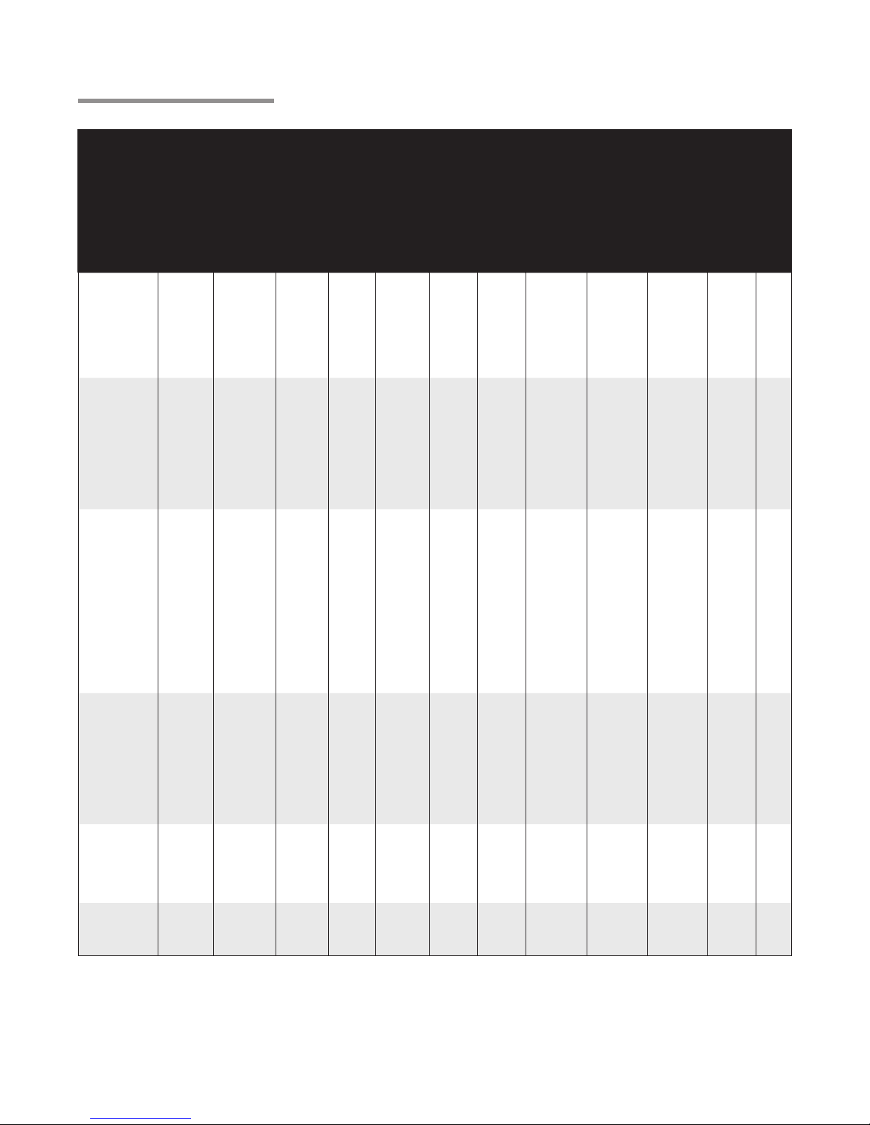
CLEARANCE TO COMBUSTIBLES
FIRE HAZARD. Always maintain published clearance to combustibles. In locations
used for the storage of combustible materials, signs must be posted. Consult manual
for additional guidelines.
MODEL
BTU/h RANGE MOUNTING
ANGLE FRONTSIDE BEHIND TOP BELOW
SIDE SIDE
TOP
BELOW
0° MOUNTING ANGLE
FRONT BEHIND
BELOW
45° MOUNTING ANGLE
TOP
BELOW
BEHINDFRONT
0° W/1 SIDE SHIELD
TOP
SIDE SIDE
BELOW
0° W/2 SIDE SHIELDS
TOP
IMPORTANT:. se high BT output when determining clearances. inimum end clearance for all models
is 12 inches. aximum mounting angle is 45. eep cover in place.
22.
.1
.
22.
1.
22.
.1
.
22.
1.
5.
14.
1.
5.
1.
5.
.1
.
4.
1.
.4
1
12
.2
2.
1
14.
1.
5.4
2.
14.1
1
1.2
.2
2.
cm in.
2
2
14
2
1
2
5
42
2
24
11
2
42
5
5
4
41
11
11
54
22.
2.
2.
22.
1.
22.
2.
2.
22.
1.
5.
2.
2.
5.
1.
5.
2.
2.
4.
1.
.4
2.
2.
.2
2.
1
2.
2.
5.4
2.
14.1
2.
2.
.2
2.
cm in.
14
2
24
2
2
1
11
4
11
41
11
15.2
25.4
15.2
15.2
15.2
15.2
25.4
15.2
15.2
15.2
15.2
25.4
15.2
15.2
15.2
15.2
25.4
15.2
15.2
15.2
15.2
25.4
15.2
15.2
15.2
15.2
25.4
15.2
15.2
15.2
15.2
25.4
15.2
15.2
15.2
cm in.
1
1
1
1
1
1
1
cm in.
4
4
4
4
44
1
1
1
1
2
2
44
44
4
2
2
4
4
4
RISQUE D’INCENDIE. Toujours respecter les dégagements prescrits de tout matériau
combustible. Dans les endroits servant au stocage de matériaux combustibles, des
écriteaux doivent en avertir. Se référer au manuel pour des directives supplémentaires.
*IMPORTANT: Déterminer les dégagements en fonction de la capacité nette de Btu maximale. e
dégagement minimal lextrémité est de 12 po pour tous les modles. angle dinclinaison maximal est de
45. Garder le couvercle en place.
(cm & in.)
!
CAUTION
MODEL /MODELE NO. INPUT BTU/H FOR USE WITH
NATURAL GAS
RADIATEUR A INFRAROUGE A FAIBLE INTENSITE
VOLTS A.C.
STARTING AMPS.
RUNNING AMPS.
120~60Hz
4.8
1.1
MANIFOLD PRESSURE
MIN. INLET PRESSURE
ORIFICE SIZE
3.5” WC
5.0” WC
#3 D.M.S
HEATER TYPE
VERSION
MIN. MOUNTING ANGLE:
COMBUSTION CHAMBER:
4” BC ALUMINUM
FOR INDOOR USE
BRANT RADIANT HEATERS LIMITED
34 SCOTT AVE., PARIS, ONTARIO
TEL: 1-519-442-7823 WWW.BRANTRADIANT.COM
ANSI Z83.20b - 2011 CSA 2.32b - 2011 Low - Intensity Infrared Htr.
ANS Z83.20b - 2011 CSA - 2011 Low - Intensity Infrared Htr.
SERIAL NO.
0870 XXXX XXXX 0001
RE-VERBER-RAY LOW INTENSITY INFRARED HEATER
FOR INDOOR INSTALLATION ONLY. NOT FOR USE IN RESIDENTIAL DWELLING.
INSTALLATION À L’EXTÉRIEUR SEULEMENT. NE PAS INSTALLER DANS UN LOGEMENT.
MAX. MOUNTING ANGLE:
0 DEGREES
45 DEGREES
FOR STAINLESS STEEL UPGRADES THE
COMBUSTION TUBE IS UPGRADED TO 409
STAINLESS STEEL.
C1
10/11
HL2-40-125N 125,000/95,000
SAMPLE
MODEL /MODELE NO. INPUT BTU/H FOR USE WITH
NATURAL GAS
RADIATEUR A INFRAROUGE A FAIBLE INTENSITE
VOLTS A.C.
STARTING AMPS.
RUNNING AMPS.
120~60Hz
4.8
1.1
MANIFOLD PRESSURE
MIN. INLET PRESSURE
ORIFICE SIZE
3.5” WC
5.0” WC
#3 D.M.S
HEATER TYPE
VERSION
MIN. MOUNTING ANGLE:
COMBUSTION CHAMBER:
4” BC ALUMINUM
FOR INDOOR USE
BRANT RADIANT HEATERS LIMITED
34 SCOTT AVE., PARIS, ONTARIO
TEL: 1-519-442-7823 WWW.BRANTRADIANT.COM
ANSI Z83.20b - 2011 CSA 2.32b - 2011 Low - Intensity Infrared Htr.
ANS Z83.20b - 2011 CSA - 2011 Low - Intensity Infrared Htr.
SERIAL NO.
0870 XXXX XXXX 0001
RE-VERBER-RAY LOW INTENSITY INFRARED HEATER
FOR INDOOR INSTALLATION ONLY. NOT FOR USE IN RESIDENTIAL DWELLING.
INSTALLATION À L’EXTÉRIEUR SEULEMENT. NE PAS INSTALLER DANS UN LOGEMENT.
MAX. MOUNTING ANGLE:
0 DEGREES
45 DEGREES
FOR STAINLESS STEEL UPGRADES THE
COMBUSTION TUBE IS UPGRADED TO 409
STAINLESS STEEL.
C1
10/11
HL2-40-125N 125,000/95,000
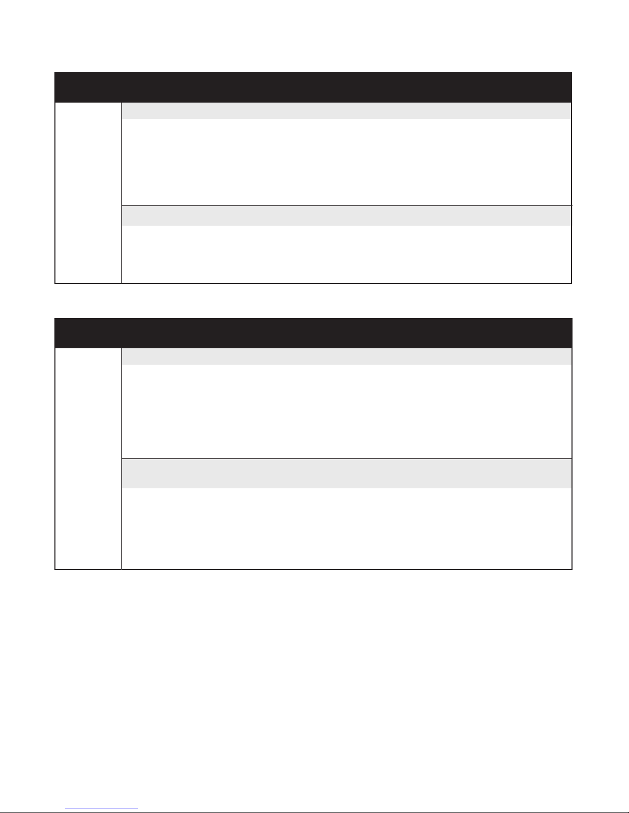
Air Metering Orifice
DO NOT REMOVETP-114
TP-3014 1 - 1/2"
Safety Labels and Their Locations
Back Panel
Top Panel
Bottom Panel
Rating
Plate
Tube Safety Label
F/N: LLTCL001
F/N: LLLOGO1
Product safety signs or labels should be replaced by the product user when they no longer are legible.
Contact either your local distributor or the product manufacturer for obtaining replacement signs or labels.
F/N: LLAC
Air Metering Orifice
Air Metering Orifice
SAMPLE
Air Metering Orifice
LLTCL001-1M-8/13 (CDS)
!
!
!
CAUTION
DANGER
WARNING
Improper installation, adjustment, alteration,service
or maintenance can cause property damage, injury
or death.
This is NOT an explosion-proof heater. Where there is the
possibility of exposure to flammable vapors or dusts, consult
the local fire marshall, your insurance carrier or authorities for
approval of the proposed installation. Do NOT install in
residential or explosive environments.
This heater must be installed and serviced by trained gas
installation and service personnel only. The installation of this
heater must conform with local building codes or, in the
absence of such codes, the National Fuel Gas Code (NFPA
54).
GAS CONNECTION
Allowances must be made for the system to expand. A
flexible gas connection of approved type is required. The
connector shall be of Type 1 hose per Exhibit “A” Section B.4.,
and Figure 1 and 2. Consult manual for further instructions.
Read and understand the installation, operating
and maintenance instructions thoroughly before
installing or servicing this equipment.
Des installation réglage, modification, maintenance
ou entretien inappropriés peuvent causer des
dommages matériels, des blessures ou la mort.
Ceci n’est PAS un radiateur antidéflagrant. En présence possible de
vapeurs ou de poussières inflammables, consulter le commissaire
des incendies local, votre compagnie d’assurance ou les autorités
compétentes pour l’approbation de l’installation projetée. NE
CONVIENT PAS aux applications résidentielles ou à tout
environnement sujet à explosion.
Ce radiateur à gaz ne doit être installé et entretenu que par du
personnel formé et qualifié à cette fin. L’installation de ce radiateur
doit être conforme aux codes locaux du bâtiment ou, en l’absence
de tels codes, du National Fuel Gas Code (NFPA 54)
RACCORDEMENT AU GAZ
Prévoir du jeu pour la dilatation du système. Un raccordement par
tube flexible approuvé pour le gaz est nécessaire. Le raccord
flexible devra être de type 1 tel qu’indiqué au schéma ‘A’, section
B.4., et aux figures 1 et 2 Se référer au manuel pour plus
d’information.
Lire et comprendre les directives d’installation, de
fonctionnement et d’entretien avant d’installer ou
d’entretenir cet équipement.
!
WARNING. To ensure system performance and
safety, this unit must be properly vented.
Improper installation, adjustment, alteration, service or
maintenance can cause property damage, injury or
death.
Des installation, réglage, modification,maintenance ou
entretien inappropriés peuvent causer des dommages
matériels, des blessures ou la mort.
This heater can be installed in various configurations as specified in the
manual.
AIRCRAFT HANGARS. This heater must be installed in accordance
with the latest edition of the Standard for Aircraft Hangars, ANSI/NFPA
409.
PUBLIC GARAGES. This heater must be installed in accordance with
the latest edition of the Standard for Parking Structures, ANSI/NFPA
88A, or the Code for Repair Garages, ANSI/NFPA 30A or the Canadian
Natural Gas and Propane Installation Code, CSA B149.1. as per
Clause 1.1.4.
VENTING. This heater’s venting system must comply with the following
requirements:
• Do not exceed 20 feet vent length or place more than two (2) 90°
elbows in the venting system.
• Use 4-DSK Vent Kit for single sidewall venting;
• Common vented models (with Y-fitting) must be wired on the same
control.
• A minimum ventilation rate of 4.0 cfm/1000
Btu/H is required for unvented operation.
Ce radiateur peut être installé dans différentes configurations tel que
spécifié dans le manuel.
HANGARS À AVIONS. Ce radiateur doit être installé en conformité avec
a dernière édition de la norme Standard for Aircraft Hangars, ANSI/NFPA
409.
GARAGES PUBLICS. Ce radiateur doit être installé en conformité avec
la dernière édition de la norme Standard for Parking Structures,
ANSI/NFPA 88, ou du Code for Repair Garages, ANSI/NFPA 30A ou, au
Canada, du Code d’installation du gaz naturel et du propane,
CSA B149.1., article 1.1.4.
ÉVACUATION. Le système d’évacuation de ce radiateur doit
satisfaire aux exigences suivantes:
• Ne pas dépasser 20 pi en longueur de conduit ou utiliser plus de 2
coudes à 90° dans le système d’évacuation.
• Utilisez l’ensemble d’évacuation RTVP-4 pour une évacuation murale
unique.
• Les modèles avec évacuation commne (avec raccord en Y ) doivent
être reliés à une même commande.
• Un taux de ventilation minimal de 4 pcm/1000 Btu/H est nécessaire
pour un fonctionnement sans système d’évacuation
AVERTISSEMENT. Pour assurer le rendement et le
fonctionnement sécuritaire du système, cet appareil
doit être ventilé de façon appropriée.
65,000* - 75,000*
W/1 side shield
W/2 side shields
20 ft. from burner
50,000* - 60,000*
W/1 side shield
W/2 side shields
20 ft. from burner
105,000* - 125,000*
W/1 side shield
W/2 side shields
20 ft. from burner
80,000* - 100,000*
W/1 side shield
W/2 side shields
20 ft. from burner
155,000* - 175,000*
W/1 side shield
W/2 side shields
20 ft. from burner
130,000* - 150,000*
W/1 side shield
W/2 side shields
20 ft. from burner
180,000* - 200,000*
W/1 side shield
W/2 side shields
20 ft. from burner
0º
45º
0º
0º
0º
0º
45º
0º
0º
0º
0º
45º
0º
0º
0º
0º
45º
0º
0º
0º
0º
45º
0º
0º
0º
0º
45º
0º
0º
0º
0º
45º
0º
0º
0º
152.4
152.4
152.4
152.4
76.2
119.4
119.4
119.4
119.4
76.2
193
193
193
193
76.2
167.6
167.6
167.6
.167.6
76.2
233.7
233.7
233.7
233.7
111.8
205.7
205.7
205.7
205.7
111.8
238.8
238.8
238.8
238.8
111.8
CLEARANCE TO COMBUSTIBLES
FIRE HAZARD. Always maintain published clearance to combustibles. In locations
used for the storage of combustible materials, signs must be posted. Consult manual
for additional guidelines.
MODEL
BTU/h RANGE MOUNTING
ANGLE
FRONT
SIDE
BEHIND
TOP BELOW
SIDE SIDE
TOP
BELOW
0° MOUNTING ANGLE
FRONT BEHIND
BELOW
45° MOUNTING ANGLE
TOP
BELOW
BEHINDFRONT
0° W/1 SIDE SHIELD
TOP
SIDE SIDE
BELOW
0° W/2 SIDE SHIELDS
TOP
IMPORTANT:. *Use high BTU output when determining clearances. Minimum end clearance for all models
is 12 inches. Maximum mounting angle is 45°. Keep cover in place.
22.9
99.1
73.7
22.9
17.8
22.9
99.1
73.7
22.9
17.8
50.8
147.3
106.7
50.8
17.8
35.6
99.1
73.7
40.6
17.8
86.4
160
127
76.2
27.9
61
147.3
106.7
58.4
27.9
104.1
160
137.2
76.2
27.9
cm in.
9
39
29
9
7
9
39
29
9
7
14
39
29
16
7
20
58
42
20
7
24
11
23
42
58
30
50
63
34
63
41
11
11
30
54
22.9
20.3
20.3
22.9
17.8
22.9
20.3
20.3
22.9
17.8
50.8
20.3
20.3
50.8
17.8
35.6
20.3
20.3
40.6
17.8
86.4
20.3
20.3
76.2
27.9
61
20.3
20.3
58.4
27.9
104.1
20.3
20.3
76.2
27.9
cm in.
9
9
8
8
9
7
8
8
8
14
7
9
23
8
8
24
7
20
8
8
20
7
16
8
11
30
8
8
34
11
8
8
41
11
30
15.2
25.4
15.2
15.2
15.2
15.2
25.4
15.2
15.2
15.2
15.2
25.4
15.2
15.2
15.2
15.2
25.4
15.2
15.2
15.2
15.2
25.4
15.2
15.2
15.2
15.2
25.4
15.2
15.2
15.2
15.2
25.4
15.2
15.2
15.2
cm in.
6
10
6
6
6
6
10
6
6
6
6
6
6
10
6
6
6
6
6
10
6
6
6
6
10
6
6
6
10
6
6
6
6
10
6
cm in.
47
47
30
47
47
60
30
60
60
60
76
76
30
30
66
66
76
66
66
76
44
81
81
81
81
92
92
44
44
94
92
92
94
94
94
RISQUE D’INCENDIE. Toujours respecter les dégagements prescrits de tout matériau
combustible. Dans les endroits servant au stockage de matériaux combustibles, des
écriteaux doivent en avertir. Se référer au manuel pour des directives supplémentaires.
*IMPORTANT: Déterminer les dégagements en fonction de la capacité nette de Btu maximale. Le dégage-
ment minimal à l’extrémité est de 12 po pour tous les modèles. L’angle d’inclinaison maximal est de 45°.
Garder le couvercle en place.
(cm & in.)
1.0 Introduction • Safety Signs and Labels