7
HL3 Series
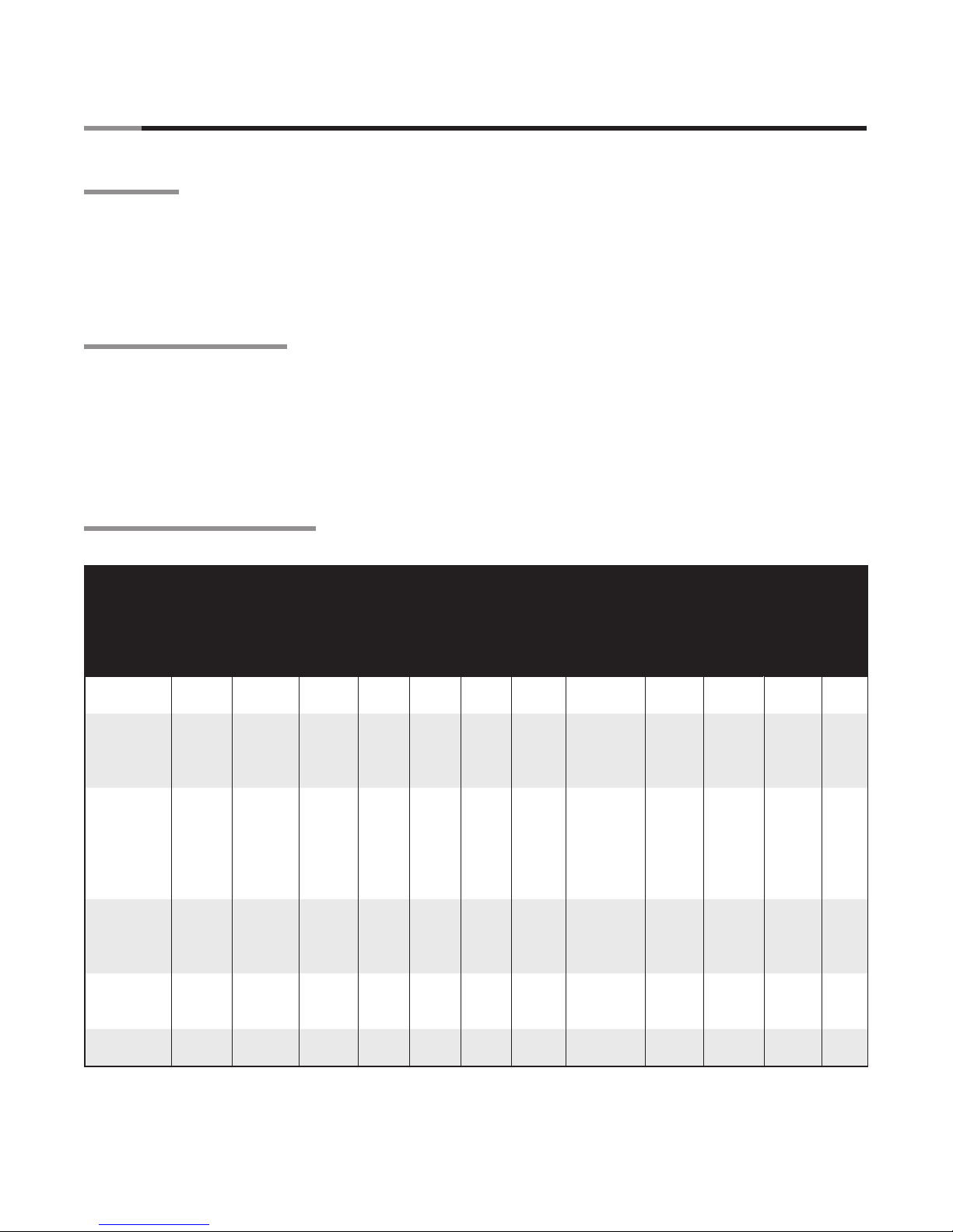
MODEL /MODELE NO. INPUT BTU/H FOR USE WITH
NATURAL GAS
RADIATEUR A INFRAROUGE A FAIBLE INTENSITE
VOLTS A.C.
STARTING AMPS.
RUNNING AMPS.
120~60Hz
4.8
1.1
MANIFOLD PRESSURE
MIN. INLET PRESSURE
ORIFICE SIZE
3.5” WC
5.0” WC
#3 D.M.S
HEATER TYPE
VERSION
MIN. MOUNTING ANGLE:
COMBUSTION CHAMBER:
4” BC TITANIUM
FOR INDOOR USE
BRANT RADIANT HEATERS LIMITED
34 SCOTT AVE., PARIS, ONTARIO
TEL: 1-519-442-7823 WWW.BRANTRADIANT.COM
ANSI Z83.20b - 2011 CSA 2.32b - 2011 Low - Intensity Infrared Htr.
ANS Z83.20b - 2011 CSA - 2011 Low - Intensity Infrared Htr.
SERIAL NO.
0870 XXXX XXXX 0001
RE-VERBER-RAY LOW INTENSITY INFRARED HEATER
FOR INDOOR INSTALLATION ONLY. NOT FOR USE IN RESIDENTIAL DWELLING.
INSTALLATION À L’EXTÉRIEUR SEULEMENT. NE PAS INSTALLER DANS UN LOGEMENT.
MAX. MOUNTING ANGLE:
0 DEGREES
45 DEGREES
FOR STAINLESS STEEL UPGRADES THE
COMBUSTION TUBE IS UPGRADED TO 409
STAINLESS STEEL.
C1
10/11
HL3-40-125N 125,000/95,000
LIGHTING INSTRUCTIONS
1. PURGE MAIN GAS SUPPLY LINE.
2. ROTATE HEATER’S MANUAL GAS
VALVE KNOB TO “ON” POSITION.
3. CLOSE ELECTRICAL CIRCUIT.
4. IF HEATER FAILS TO LIGHT, TURN
OFF GAS AND WAIT 5 MINUTES
BEFORE REPEATING ABOVE.
INSTRUCTIONS POUR L’ALLUMAGE
1. PURGER LA CONDUITE D’ALIMENTATION
EN GAZ PRINCIPALE.
2. TOURNER LE BOUTON DU ROBINET
DE GAS A COMMANDE MANUELLE
JUSQU’A CE QU’IL SE TROUVE EN
POSITION DE MARCHE (“ON”)
3. FERMER LE CIRCUIT ELECTRIQUE.
4. SI L’APPAREIL DE CHAUFFAGE NE
S’ALLUME PAS, ATTENDRE 5 MINUTES
AVANT DE SUIVRE DE NOUVEAU LES
INSTRUCTIONS CI-DESSUS.
TO SHUT DOWN
1. ROTATE HEATER’S MANUAL GAS
VALVE KNOB TO “OFF” POSITION.
2. OPEN ELECTRICAL CIRCUIT.
POUR ETEINDRE L’APPAREIL
1. TOURNER LE BOUTON DU ROBINET
DE GA A COMMANDE MANUELLE
DE L’APPAREIL DE CHAUFFAGE
USU’A CE U’IL DE TROUVE EN
POSITION D’ARRET “OFF”.
2. OUVRIR LE CIRCUIT ELECTRIUE.
BRANT RADIANT HEATERS LIMITED
34 SCOTT AVENUE, PARIS ON. N3L 3R1
TELEPHONE 5144223
WWW.BRANTRADIANT.COM
Rating
Plate
Controls Compartment
Fan Compartment
Combustion Chamber
MODEL /MODELE NO. INPUT BTU/H FOR USE WITH
NATURAL GAS
RADIATEUR A INFRAROUGE A FAIBLE INTENSITE
VOLTS A.C.
STARTING AMPS.
RUNNING AMPS.
120~60Hz
4.8
1.1
MANIFOLD PRESSURE
MIN. INLET PRESSURE
ORIFICE SIZE
3.5” WC
5.0” WC
#3 D.M.S
HEATER TYPE
VERSION
MIN. MOUNTING ANGLE:
COMBUSTION CHAMBER:
4” BC ALUMINUM
FOR INDOOR USE
BRANT RADIANT HEATERS LIMITED
34 SCOTT AVE., PARIS, ONTARIO
TEL: 1-519-442-7823 WWW.BRANTRADIANT.COM
ANSI Z83.20b - 2011 CSA 2.32b - 2011 Low - Intensity Infrared Htr.
ANS Z83.20b - 2011 CSA - 2011 Low - Intensity Infrared Htr.
SERIAL NO.
0870 XXXX XXXX 0001
RE-VERBER-RAY LOW INTENSITY INFRARED HEATER
FOR INDOOR INSTALLATION ONLY. NOT FOR USE IN RESIDENTIAL DWELLING.
INSTALLATION À L’EXTÉRIEUR SEULEMENT. NE PAS INSTALLER DANS UN LOGEMENT.
MAX. MOUNTING ANGLE:
0 DEGREES
45 DEGREES
FOR STAINLESS STEEL UPGRADES THE
COMBUSTION TUBE IS UPGRADED TO 409
STAINLESS STEEL.
C1
10/11
HL3-40-125N 125,000/95,000
HL3
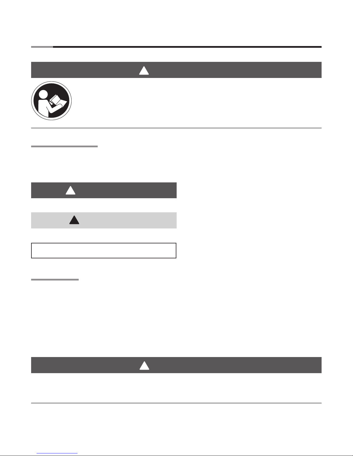
SERVICE ACCESS PANEL
SERVICE ACCESS PANEL
COMPARTIMENT VENTILATEUR
FAN COMPARTMENT
1. Disconnect gas & electricity.
2. Remove top cover
(2 thumbsscrews).
3. Remove six (6) 1/4” screws.
4. Lift and remove panel.
1. Débrancher le gaz et l’electricité.
2. Retirer les 2 vis à main du couvercle
supérieur.
3. Retirer les 6 vis 1/4 po.
4. Soulever et retirer le panneau.
GARDER LE COUVERCLE EN PLACE. NE L’ENLEVER QUE POUR L’ENTRETIEN.
Radiant Tube(s)
2.0 Safety • Safety Labels and Locations
16” Burner Tube
SAMPLE
Lighting /Shut Down Instructions Label
Yellow Titanium Alloy Tag
(150,000 BTU/H models and greater)
F/N: LLTB026
F/N: LLTB025R
F/N: LLTB024L