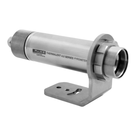
Fluke Thermalert 4.0 User manual

Thermalert®4.0 Series
Smart Integrated Infrared Sensors
Users Manual
PN 4968276, English, Rev. 1.1, May 2018
© 2018 Fluke Process Instruments. All rights reserved. Printed in Germany. Specifications subject to change without notice.
All product names are trademarks of their respective companies.
www. .com information@itm.com1.800.561.8187

Warranty
The manufacturer warrants this instrument to be free from defects in material and workmanship under normal use
and service for the period of two years from date of purchase. This warranty extends only to the original purchaser.
This warranty shall not apply to fuses, batteries or any product which has been subject to misuse, neglect, accident,
or abnormal conditions of operation.
In the event of failure of a product covered by this warranty, the manufacturer will repair the instrument when it is
returned by the purchaser, freight prepaid, to an authorized Service Facility within the applicable warranty period,
provided manufacturer’s examination discloses to its satisfaction that the product was defective. The manufacturer
may, at its option, replace the product in lieu of repair. With regard to any covered product returned within the
applicable warranty period, repairs or replacement will be made without charge and with return freight paid by the
manufacturer, unless the failure was caused by misuse, neglect, accident, or abnormal conditions of operation or
storage, in which case repairs will be billed at a reasonable cost. In such a case, an estimate will be submitted
before work is started, if requested.
The foregoing warranty is in lieu of all other warranties, expressed or implied, including but not limited to any
implied warranty of merchantability, fitness, or adequacy for any particular purpose or use. The manufacturer shall
not be liable for any special, incidental or consequential damages, whether in contract, tort, or otherwise.
Software Warranty
The manufacturer does not warrant that the software described herein will function properly in every hardware and
software environment. This software may not work in combination with modified or emulated versions of Windows
operating environments, memory-resident software, or on computers with inadequate memory. The manufacturer
warrants that the program disk is free from defects in material and workmanship, assuming normal use, for a period
of one year. Except for this warranty, the manufacturer makes no warranty or representation, either expressed or
implied, with respect to this software or documentation, including its quality, performance, merchantability, or
fitness for a particular purpose. As a result, this software and documentation are licensed “as is,” and the licensee
(i.e., the User) assumes the entire risk as to its quality and performance. The liability of the manufacturer under
this warranty shall be limited to the amount paid by the User. In no event shall the manufacturer be liable for any
costs including but not limited to those incurred as a result of lost profits or revenue, loss of use of the computer
software, loss of data, the cost of substitute software, claims by third parties, or for other similar costs. The
manufacturer’s software and documentation are copyrighted with all rights reserved. It is illegal to make copies for
another person.
www. .com information@itm.com1.800.561.8187

Table of Contents
Chapter Page
TABLE OF CONTENTS ................................................................................................................................................ 3
LIST OF TABLES ....................................................................................................................................................... 7
LIST OF FIGURES ...................................................................................................................................................... 8
COMPLIANCE STATEMENT ....................................................................................................................................... 10
SAFETY INFORMATION............................................................................................................................................. 11
CONTACTS............................................................................................................................................................. 15
1DESCRIPTION....................................................................................................................................................... 16
2TECHNICAL DATA................................................................................................................................................. 18
2.1 Measurement Specification.............................................................................................................................................................................18
2.2 Optical Specifications......................................................................................................................................................................................20
2.3 Electrical Specifications ..................................................................................................................................................................................21
2.3.1 Model 2-Wire..........................................................................................................................................................................................21
2.3.2 Model 6-Wire..........................................................................................................................................................................................21
2.3.3 Model 12-Wire........................................................................................................................................................................................21
2.4 Environmental Specifications..........................................................................................................................................................................22
2.5 Dimensions......................................................................................................................................................................................................23
2.5.1 Model 2-Wire / 6-Wire............................................................................................................................................................................23
2.5.2 Model 12-Wire........................................................................................................................................................................................23
2.6 Scope of Delivery............................................................................................................................................................................................24
3BASICS ............................................................................................................................................................... 25
3.1 Measurement of Infrared Temperature...........................................................................................................................................................25
3.2 Emissivity of Target Object .............................................................................................................................................................................25
4ENVIRONMENT ..................................................................................................................................................... 26
4.1 Ambient Temperature .....................................................................................................................................................................................26
4.2 Atmospheric Quality........................................................................................................................................................................................26
4.3 Electrical Interference .....................................................................................................................................................................................26
5INSTALLATION...................................................................................................................................................... 28
5.1 Positioning.......................................................................................................................................................................................................28
5.2 Distance to Object...........................................................................................................................................................................................28
5.3 Viewing Angles................................................................................................................................................................................................29
5.4 Model 2-Wire...................................................................................................................................................................................................29
5.4.1 Back Panel.............................................................................................................................................................................................29
5.4.2 Cable Connection ..................................................................................................................................................................................30
5.4.3 mA Single Loop......................................................................................................................................................................................33
5.4.4 mA Multiple Loops .................................................................................................................................................................................35
www. .com information@itm.com1.800.561.8187

5.4.5 Alarm Output AL.................................................................................................................................................................................... 35
5.5 Model 6-Wire................................................................................................................................................................................................... 36
5.5.1 Back Panel............................................................................................................................................................................................. 36
5.5.2 Cable Connection.................................................................................................................................................................................. 36
5.5.3 Terminal Strip ........................................................................................................................................................................................ 36
5.5.4 Analog Out............................................................................................................................................................................................. 36
5.5.4.1 mA Output ....................................................................................................................................................................................... 36
5.5.4.2 V Output .......................................................................................................................................................................................... 37
5.5.4.3 TC Output........................................................................................................................................................................................ 37
5.5.5 RS485 Communication ......................................................................................................................................................................... 37
5.6 Model 12-Wire................................................................................................................................................................................................. 37
5.6.1 Back Panel............................................................................................................................................................................................. 37
5.6.2 RS485 Communication ......................................................................................................................................................................... 38
5.6.3 FTC1 –Emissivity Setting ..................................................................................................................................................................... 38
5.6.4 FTC2 –Background Temperature Compensation................................................................................................................................ 38
5.6.5 Trigger Input .......................................................................................................................................................................................... 40
5.6.5.1 Reset ............................................................................................................................................................................................... 40
5.6.5.2 Hold ................................................................................................................................................................................................. 40
5.6.5.3 Laser................................................................................................................................................................................................ 41
5.6.6 Relay Output.......................................................................................................................................................................................... 41
5.6.7 Analog Out............................................................................................................................................................................................. 41
5.6.7.1 mA Output ....................................................................................................................................................................................... 41
5.6.7.2 V Output .......................................................................................................................................................................................... 42
6RS485................................................................................................................................................................43
6.1 Specification.................................................................................................................................................................................................... 43
6.2 Installation....................................................................................................................................................................................................... 43
6.3 Wiring.............................................................................................................................................................................................................. 44
6.3.1 Model 6-Wire......................................................................................................................................................................................... 44
6.3.2 Model 12-Wire ....................................................................................................................................................................................... 44
6.3.3 Computer Interfacing............................................................................................................................................................................. 44
6.3.4 Multiple Sensors.................................................................................................................................................................................... 45
7OPERATION..........................................................................................................................................................46
7.1 Laser............................................................................................................................................................................................................... 46
7.2 Post Processing.............................................................................................................................................................................................. 46
7.2.1 Averaging............................................................................................................................................................................................... 46
7.2.2 Peak Hold .............................................................................................................................................................................................. 47
7.2.3 Valley Hold............................................................................................................................................................................................. 47
7.2.4 Advanced Peak Hold............................................................................................................................................................................. 48
7.2.5 Advanced Valley Hold ........................................................................................................................................................................... 49
7.2.6 Advanced Peak Hold with Averaging.................................................................................................................................................... 49
7.2.7 Advanced Valley Hold with Averaging .................................................................................................................................................. 49
www. .com information@itm.com1.800.561.8187

8ACCESSORIES ..................................................................................................................................................... 50
8.1 Electrical Accessories .....................................................................................................................................................................................50
8.1.1 High Temp Cable 12-Wire (A-CB-HT-M16-W12-xx).............................................................................................................................51
8.1.2 Low Temp Cable 12-Wire (A-CB-LT-M16-W12-xx)...............................................................................................................................53
8.1.3 Terminal Block (A-T40-TB)....................................................................................................................................................................55
8.1.4 Terminal Block with Enclosure (A-T40-TB-ENC) ..................................................................................................................................56
8.1.5 Power Supply DIN Rail (A-PS-DIN-24V)...............................................................................................................................................57
8.1.6 Power Supply with Terminal Box (A-PS-ENC-24V) ..............................................................................................................................58
8.1.7 USB/RS485 Converter (A-CONV-USB485) ..........................................................................................................................................59
8.2 Mechanical Accessories..................................................................................................................................................................................60
8.2.1 Mounting Nut (A-MN).............................................................................................................................................................................61
8.2.2 Fixed Bracket (A-BR-F)..........................................................................................................................................................................62
8.2.3 Adjustable Bracket (A-BR-A).................................................................................................................................................................63
8.2.4 Swivel Bracket (A-BR-S)........................................................................................................................................................................64
8.2.5 Sighting Tube (A-ST-xx) ........................................................................................................................................................................65
8.2.6 Pipe Adapter (A-PA) ..............................................................................................................................................................................67
8.2.7 Protective Windows (A-T40-PW-xx)......................................................................................................................................................68
8.2.8 Right Angle Mirror (A-MIR-RA)..............................................................................................................................................................69
8.2.9 Air Purge (A-AP) ....................................................................................................................................................................................70
8.2.10 Air/Water-Cooled Housing (A-T40-WC) ..............................................................................................................................................71
8.2.10.1 Avoidance of Condensation...........................................................................................................................................................72
8.2.11 Thread Adapter (A-TA-M56)................................................................................................................................................................74
8.2.12 Mounting Flange (A-MF-MOD)............................................................................................................................................................75
9MAINTENANCE ..................................................................................................................................................... 76
9.1 Troubleshooting Minor Problems....................................................................................................................................................................76
9.2 Fail-Safe Operation.........................................................................................................................................................................................76
9.3 Cleaning the Lens ...........................................................................................................................................................................................76
10 PROGRAMMING GUIDE........................................................................................................................................ 78
10.1 Command Structure......................................................................................................................................................................................78
10.1.1 Requesting a Parameter (Poll Mode) ..................................................................................................................................................78
10.1.2 Setting a Parameter (Poll Mode) .........................................................................................................................................................78
10.1.3 Sensor Response ................................................................................................................................................................................78
10.1.4 Sensor Notification...............................................................................................................................................................................78
10.1.5 Error Messages....................................................................................................................................................................................78
10.2 Transfer Modes .............................................................................................................................................................................................79
10.3 Sensor Information........................................................................................................................................................................................79
10.4 Sensor Setup.................................................................................................................................................................................................79
10.4.1 General Settings..................................................................................................................................................................................79
10.4.2 Emissivity Setting.................................................................................................................................................................................80
10.4.3 Background Temperature Compensation ...........................................................................................................................................80
10.4.4 Temperature Hold Functions...............................................................................................................................................................80
www. .com information@itm.com1.800.561.8187

10.5 Sensor Control.............................................................................................................................................................................................. 81
10.5.1 Analog Output...................................................................................................................................................................................... 81
10.5.2 Relay Output........................................................................................................................................................................................ 81
10.6 RS485 Communication................................................................................................................................................................................. 81
10.7 Multidrop Mode............................................................................................................................................................................................. 81
10.8 Command List............................................................................................................................................................................................... 83
11 APPENDIX ..........................................................................................................................................................87
11.1 Optical Diagrams .......................................................................................................................................................................................... 87
11.1.1 LT-07 Models....................................................................................................................................................................................... 87
11.1.2 LT-15 Models....................................................................................................................................................................................... 87
11.1.3 LT-30 Models....................................................................................................................................................................................... 88
11.1.4 LT-50 Models....................................................................................................................................................................................... 89
11.1.5 LT-70 Models....................................................................................................................................................................................... 90
11.1.6 P7-30 Models ...................................................................................................................................................................................... 90
11.1.7 G7-70 Models...................................................................................................................................................................................... 91
11.1.8 G5-30 Models...................................................................................................................................................................................... 91
11.1.9 G5-70 Models...................................................................................................................................................................................... 91
11.1.10 MT-30 Models.................................................................................................................................................................................... 92
11.1.11 MT-70 Models.................................................................................................................................................................................... 93
11.1.12 P3-20 Models .................................................................................................................................................................................... 94
11.1.13 HT-60 Models.................................................................................................................................................................................... 95
11.2 Determination of Emissivity.......................................................................................................................................................................... 96
11.3 Typical Emissivity Values ............................................................................................................................................................................. 96
www. .com information@itm.com1.800.561.8187

List of Tables
Table Page
Table 5-1: Terminal Connections......................................................................................................................... 30
Table 5-2: Power Supply Requirements for Multiple Loads ................................................................................. 34
Table 5-3: Pin Assignment for Terminal Strip....................................................................................................... 36
Table 5-4: Pin Assignment for DIN Connector..................................................................................................... 38
Table 5-5: Ratio between Analog Input Voltage and Emissivity........................................................................... 38
Table 8-6: Available Cable Lengths ..................................................................................................................... 51
Table 8-7: Available Cable Lengths ..................................................................................................................... 53
Table 8-8: Protective Windows............................................................................................................................. 68
Table 8-9: Minimum device temperatures [°C/°F] ................................................................................................ 73
Table 9-10: Troubleshooting................................................................................................................................ 76
Table 9-11: Error Codes for Analog Output.......................................................................................................... 76
Table 9-12: Error Codes via Field Bus................................................................................................................. 76
Table 10-13: Sensor Information.......................................................................................................................... 79
Table 10-14: Overview to Temperature Hold Functions....................................................................................... 80
www. .com information@itm.com1.800.561.8187

List of Figures
Figure Page
Figure 1-1: Available Models ................................................................................................................................17
Figure 2-1: Dimensions for the 2-Wire and 6-Wire Model.....................................................................................23
Figure 2-2: Dimensions for the 12-Wire Model .....................................................................................................23
Figure 4-1: One Earth Ground at the Sensor (left) or at the Power Supply (right).................................................26
Figure 4-2: Principle of the Galvanic Isolation for the 6-Wire Model .....................................................................27
Figure 4-3: Principle of the Galvanic Isolation for the 12-Wire Model ...................................................................27
Figure 5-1: Proper Sensor Placement...................................................................................................................28
Figure 5-2: Acceptable Sensor Viewing Angles....................................................................................................29
Figure 5-3: Rear Panel for 2-Wire Sensor.............................................................................................................29
Figure 5-4: Principle Circuit Diagram: Infrared Sensor with Multiple Loads ..........................................................33
Figure 5-5: Equivalent Circuit Diagram: Infrared Sensor with Multiple Loads .......................................................34
Figure 5-6: Principle Circuit Diagram: Infrared Sensor with Multiple Loads ..........................................................35
Figure 5-7: Exemplary Wiring the Alarm Output AL for the 2-Wire Sensor...........................................................35
Figure 5-8: Rear Panel for 6-Wire Sensor.............................................................................................................36
Figure 5-9: Wiring Analog Out as Current Output.................................................................................................37
Figure 5-10: Wiring Analog Out as Voltage Output...............................................................................................37
Figure 5-11: DIN Connector Pin Layout (pin side) ................................................................................................37
Figure 5-12: Adjustment of Emissivity at FTC1 Input (Example)...........................................................................38
Figure 5-13: Principle of Background Temperature Compensation ......................................................................39
Figure 5-14: Adjustment of Background Temperature Compensation at FTC2 Input (Example)..........................40
Figure 5-15: Wiring the Trigger Input....................................................................................................................40
Figure 5-16: Resetting the Peak Hold Function....................................................................................................40
Figure 5-17: Holding the Output Temperature......................................................................................................41
Figure 5-18: Spike Voltage Limitation for the Alarm Relay....................................................................................41
Figure 5-19: Wiring Analog Out as Current Output...............................................................................................42
Figure 5-20: Wiring Analog Out as Voltage Output...............................................................................................42
Figure 6-1: Network in Linear Topology (daisy chain)...........................................................................................43
Figure 6-2: Wiring RS485 Communication for 6-Wire Model................................................................................44
Figure 6-3: Wiring RS485 Communication for 12-Wire Model..............................................................................44
Figure 6-4: Wiring the Sensor’s RS485 Interface with USB/RS485 Converter in 2-Wire Mode ............................45
Figure 6-5: Wiring the Multiple Sensors via RS485 Interface with USB/RS485 Converter in 2-Wire Mode..........45
Figure 7-1: Laser Indication..................................................................................................................................46
Figure 7-2: Averaging ...........................................................................................................................................47
Figure 7-3: Peak Hold...........................................................................................................................................47
Figure 7-4: Valley Hold .........................................................................................................................................48
Figure 7-5: Advanced Peak Hold..........................................................................................................................48
Figure 7-6: Advanced Peak Hold with Averaging..................................................................................................49
Figure 8-1: High Temp Cable (12-Wire)................................................................................................................51
Figure 8-2: Low Temp Cable (12-Wire).................................................................................................................53
Figure 8-3: Terminal Block with Wire Color Assignment.......................................................................................55
www. .com information@itm.com1.800.561.8187

Figure 8-4: Terminal Block in an Enclosure ......................................................................................................... 56
Figure 8-5: Industrial Power Supply..................................................................................................................... 57
Figure 8-6: Power Supply with Terminal Box ....................................................................................................... 58
Figure 8-7: USB/RS485 Converter....................................................................................................................... 59
Figure 8-8: Overview to Mechanical Accessories................................................................................................. 60
Figure 8-9: Mounting Nut ..................................................................................................................................... 61
Figure 8-10: Fixed Bracket................................................................................................................................... 62
Figure 8-11: Adjustable Bracket........................................................................................................................... 63
Figure 8-12: Swivel Bracket................................................................................................................................. 64
Figure 8-13: Installation of the Sighting Tube....................................................................................................... 65
Figure 8-14: Dimensions for the Sighting Tube.................................................................................................... 65
Figure 8-15: Available Sighting Tubes ................................................................................................................. 65
Figure 8-16: Pipe Adapter.................................................................................................................................... 67
Figure 8-17: Protective Window........................................................................................................................... 68
Figure 8-18: Right Angle Mirror............................................................................................................................ 69
Figure 8-19: Air Purge Collar ............................................................................................................................... 70
Figure 8-20: Air/Water-Cooled Housing............................................................................................................... 71
Figure 8-21: Thread Adapter................................................................................................................................ 74
Figure 8-22: Mounting Flange.............................................................................................................................. 75
Figure 11-1: Optical Diagrams LT-07 Models ...................................................................................................... 87
Figure 11-2: Optical Diagrams LT-15 Models ...................................................................................................... 87
Figure 11-3: Optical Diagrams LT-30 Models ...................................................................................................... 88
Figure 11-4: Optical Diagrams LT-50 Models ...................................................................................................... 89
Figure 11-5: Optical Diagrams LT-70 Models ...................................................................................................... 90
Figure 11-6: Optical Diagrams P7-30 Models...................................................................................................... 90
Figure 11-7: Optical Diagrams G7-70 Models...................................................................................................... 91
Figure 11-8: Optical Diagrams G5-30 Models...................................................................................................... 91
Figure 11-9: Optical Diagrams G5-70 Models...................................................................................................... 91
Figure 11-10: Optical Diagrams MT-30 Models ................................................................................................... 92
Figure 11-11: Optical Diagrams MT-70 Models ................................................................................................... 93
Figure 11-12: Optical DiagramsP3-20 Models..................................................................................................... 94
Figure 11-13: Optical Diagrams HT-60 Models.................................................................................................... 95
www. .com information@itm.com1.800.561.8187

Compliance Statement
The device complies with the requirements of the European Directives:
EC –Directive 2014/30/EU –EMC
EC –Directive 2011/65/EU –RoHS II
EN 61326-1: 2013 Electrical measurement, control and laboratory devices -
Electromagnetic susceptibility (EMC)
EN 50581: 2012 Technical documentation for the evaluation of electrical products with respect to
restriction of hazardous substances (RoHS)
Electromagnetic Compatibility Applies to use in Korea only. Class A Equipment
(Industrial Broadcasting & Communication Equipment)
This product meets requirements for industrial (Class A) electromagnetic wave
equipment and the seller or user should take notice of it. This equipment is intended
for use in business environments and is not to be used in homes.
www. .com information@itm.com1.800.561.8187

Safety Information
This document contains important information, which should be kept at all times with the instrument during its
operational life. Other users of this instrument should be given these instructions with the instrument. Eventual
updates to this information must be added to the original document. The instrument can only be operated by trained
personnel in accordance with these instructions and local safety regulations.
Acceptable Operation
This instrument is intended only for the measurement of temperature. The instrument is appropriate for continuous
use. The instrument operates reliably in demanding conditions, such as in high environmental temperatures, as
long as the documented technical specifications for all instrument components are adhered to. Compliance with
the operating instructions is necessary to ensure the expected results.
Unacceptable Operation
The instrument should not be used for medical diagnosis.
Replacement Parts and Accessories
Use only original parts and accessories approved by themanufacturer. The use of other products can compromise
the operation safety and functionality of the instrument.
www. .com information@itm.com1.800.561.8187

Safety Symbol
Description
Read all safety information before in the handbook
Hazardous voltage. Risk of electrical shock.
Warning. Risk of danger. Important information. See manual.
Laser warning
Earth (ground) terminal
Protective conductor terminal
Switch or relay contact
DC power supply
Conforms to European Union directive.
Disposal of old instruments should be handled according to professional and
environmental regulations as electronic waste.
Conforms to relevant South Korean EMC Standards.
Certified by CSA group to North American Safety Standards
International Ingress Protection Marking
China RoHS
IP65
www. .com information@itm.com1.800.561.8187

To prevent possible electrical shock, fire, or personal injury follow these guidelines:
•Read all safety information before you use the product.
•Use the product only as specified, or the protection supplied by the product can be
compromised.
•Do not use the product around explosive gases, vapor, or in damp or wet environments.
•Carefully read all instructions.
•Do not use and disable the product if it is damaged.
•Do not use the product if it operates incorrectly.
•Do not apply more than the rated voltage between the terminals or each terminal and earth
ground.
•Do not look directly into the laser with optical tools (for example, binoculars, telescopes,
microscopes). Optical tools can focus the laser and be dangerous to the eye.
•Do not look into the laser. Do not point laser directly at persons or animals or indirectly off
reflective surfaces.
•Do not use laser viewing glasses as laser protection glasses. Laser viewing glasses are used
only for better visibility of the laser in bright light.
•Use the product only as specified or hazardous laser radiation exposure can occur.
•Incorrect wiring can damage the sensor and void the warranty. Before applying power, make
sure all connections are correct and secure!
•To prevent possible electrical shock, fire, or personal injury make sure that the sensor is
grounded before use.
•Have an approved technician repair the product.
•The metallic enclosure of the sensor is not necessarily earthed by installation. At least one of the
following safety measures must be met to minimize the danger of electrostatic charges:
oEarth grounding of the cable shield
oInstalling the unit’s metallic enclosure on an earth grounded mounting bracket or on any other
grounded bases
oProtect the operator from electrostatic discharge
www. .com information@itm.com1.800.561.8187

Thermalert®4.0 Series
Users Manual, Rev. 1.1, May 2018
16
1 Description
The Thermalert 4.0 sensor is an infrared thermometer that differs in spectral responses to be capable of covering
a broad range of applications such as metal, glass, and plastics.
The Thermalert 4.0 Series introduces improved temperature measurement specifications, an extended operating
ambient temperature range, multiple user interfaces and various network communications. Everything is packaged
in a sealed stainless steel housing rated IP65 (NEMA 4).
The Thermalert 4.0 Series comes with the following features:
•Wide temperature range from -40 to 2250°C (-40 to 4082°F)
•Multiple spectral models for any kind of application
•Wide choice of optics
•Fast response time down to 30 ms
•Laser sighting
•Compact, rugged design in stainless steel
•Galvanic isolated outputs
•Real-time ambient background temperature compensation
•Simple, two-wire installation or digital communications RS485
•Rugged accessories for harsh industrial environments
•Software for remote configuration, monitoring and field calibration
The following Thermalert 4.0 model variants are available:
T40
–
XX
–
XX
–
XXX
–
X
|
|
|
|
|
Series
Spectral:
LT
MT
HT
G5
G7
P3
P7
Optics:
07
15
20
30
50
60
70
Focus:
SF0
SF2
SF4
CF0
CF1
CF2
Interface:
0(2 wire)
1(6 wire)
2(12 wire)
Example: T40-LT-15-SF0-0
www. .com information@itm.com1.800.561.8187

Description
Measurement Specification
17
1
Figure 1-1: Available Models
2-Wire
4 to 20 mA, Alarm, USB 6-Wire
Analog Out, RS485, USB
12-Wire
Analog In/Out, Alarm, Trigger, RS485, USB
www. .com information@itm.com1.800.561.8187

Thermalert®4.0 Series
Users Manual, Rev. 1.1, May 2018
18
2 Technical Data
2.1 Measurement Specification
Temperature Range
LT-07 -20 to 600°C (-4 to 1112°F)
LT-15 -20 to 600°C (-4 to 1112°F)
LT-30 -20 to 600°C (-4 to 1112°F)
LT-50 -40 to 1000°C (-40 to 1832°F)
LT-70 -40 to 1000°C (-40 to 1832°F)
P7-30 10 to 360°C (50 to 680°F)
G7-70 300 to 900°C (572 to 1652°F)
G5-30 250 to 1650°C (482 to 3002°F)
G5-70 450 to 2250°C (842 to 4082°F)
MT-30 200 to 1000°C (392 to 1832°F)
MT-70 450 to 2250°C (842 to 4082°F)
P3-20 25 to 450°C (77 to 842°F)
HT-60 500 to 2000°C (932 to 3632°F)
Spectral Response
LT-07 8 to 14 µm
LT-15 8 to 14 µm
LT-30 8 to 14 µm
LT-50 8 to 14 µm
LT-70 8 to 14 µm
P7-30 7.9 µm
G7-70 7.9 µm
G5-30 5 µm
G5-70 5 µm
MT-30 3.9 µm
MT-70 3.9 µm
P3-20 3.43 µm
HT-60 2.2 µm
Response Time
1
LT-07 150 ms
LT-15 150 ms
LT-30 30 ms
LT-50 130 ms
LT-70 130 ms
P7-30 130 ms
G7-70 130 ms
G5-30 60 ms
1
90% value
www. .com information@itm.com1.800.561.8187

Technical Data
Measurement Specification
19
2
G5-70 60 ms
MT-30 130 ms
MT-70 130 ms
P3-20 130 ms
2
HT-60 130 ms
System Accuracy
3
P3 ± (3°C + 1% of reading) for Tmeas > 75°C (167°F)
All other ± 1% of reading or ± 1.0°C (2.0°F) for Tmeas > 0°C (32°F)
for Tmeas ≤0°C (32°F):
± [1.0°C + 0.1*(0°C –Tmeas)] with Tmeas in °C
± [2.0°F + 0.1*(32°F –Tmeas)] with Tmeas in °F
Repeatability
4
P3 ± 1°C (2°F) or 0.5% of reading, whichever is greater
All other ± 0.3°C (0.6°F) or 0.3% of reading, whichever is greater
Temperature Resolution
Digital output 0.1°C (0.1°F)
Analog output 14 bit
Emissivity
6-wire / 12-wire models 0.100 to 1.100, in 0.001 increments
2-wire models 0.10 to 1.00, in 0.01 increments
Signal Processing
All models Averaging, peak hold, valley hold, advanced peak hold, advanced valley hold,
ambient background temperature compensation
2
10 s for Ttarget < 150°C (302°F)
3
at ambient temperature 23°C ± 5°C (73°F ± 9°F), emissivity = 1.0 and calibration geometry
4
at ambient temperature 23°C ± 5°C (73°F ± 9°F), emissivity = 1.0 and calibration geometry
www. .com information@itm.com1.800.561.8187

Thermalert®4.0 Series
Users Manual, Rev. 1.1, May 2018
20
2.2 Optical Specifications
Optical Resolution D:S
5
Focus Distances
LT-07 7:1 CF0 (plastic lens)
LT-15 15:1 SF0 (plastic lens)
LT-30 33:1 SF0, CF1, CF2
LT-50 50:1 SF0, CF2
LT-70 70:1 SF2, CF2
P7-30 33:1 SF0
G7-70 70:1 SF2
G5-30 33:1 SF0
G5-70 70:1 SF2
MT-30 33:1 SF0, CF1, CF2
MT-70 70:1 SF2, CF1, CF2
P3-20 20:1 SF4
HT-60 60:1 SF0, CF1, CF2
Focus Distances
SF0 1520 mm (60 in)
SF2 1250 mm (49 in)
SF4 500 mm (20 in)
CF0 50 mm (2 in)
CF1 76 mm (3 in)
CF2 200 mm (7.9 in)
Note
The focus distance is measured from the lens of the sensor.
For units with air/water-cooled housing, you have to subtract 70 mm (2.8 in) from the focus distance.
For units with ThermoJacket, you have to subtract 55 mm (2.2 in) from the focus distance.
These considerations are very important, especially for sensors with close focus optic!
For detailed optical charts, see section 11.1 Optical Diagrams, page 87.
Laser
All models laser available per standard (except LT-07, LT-15, and P3 models)
2-wire devices require an additional power supply via USB
5
at 90% energy, specified D:S ratio at focus point only
www. .com information@itm.com1.800.561.8187

Technical Data
Electrical Specifications
21
2
2.3 Electrical Specifications
2.3.1 Model 2-Wire
Power 12 to 24 VDC
Outputs
Analog 4 to 20 mA, loop impedance max. 500 Ω
Alarm 24 V / 150 mA
Digital USB: version 2.0, micro-B connector (only for the setup of the instrument)
2.3.2 Model 6-Wire
Power + 24 VDC nominal (20 to 48 VDC), 100 mA @ 24 V
Outputs
Analog 0 to 20 mA (active), or
4 to 20 mA (active), or
0 to 10 V, or
J thermocouple, or
K thermocouple
current loop impedance: max. 500 Ω
voltage load impedance: min. 5 kΩ
electrically isolated from power supply
Digital USB: version 2.0, micro-B connector (only for the setup of the instrument)
RS485: networkable to 32 sensors,
baud rate: 4800, 9600, 19200, 38400, 57600, 115200 Bit/s (default: 9600 Bit/s)
2.3.3 Model 12-Wire
Power + 24 VDC nominal (20 to 48 VDC), 100 mA @ 24 V
Outputs
Analog 0 to 20 mA (active), or
4 to 20 mA (active), or
0 to 10 V
current loop impedance: max. 500 Ω
voltage load impedance: min. 5 kΩ
electrically isolated from power supply
Alarm 48 V / 300 mA
1 potential-free relay output with wear-free contacts (solid state relay),
electrically isolated from power supply
Input
Analog 0 to 10 V
emissivity setting, or
background temperature compensation
Digital trigger input (closing contact)
Digital USB: version 2.0, micro-B connector (only for the setup of the instrument)
RS485: networkable to 32 sensors,
baud rate: 4800, 9600, 19200, 38400, 57600, 115200 Bit/s (default: 9600 Bit/s)
www. .com information@itm.com1.800.561.8187

Thermalert®4.0 Series
Users Manual, Rev. 1.1, May 2018
22
2.4 Environmental Specifications
Ingress Protection IP65 / IEC 60529 (NEMA-4)
Operating temperature -20 to 85°C (-4 to 185°F) without cooling
10 to 120°C (50 to 250°F) with air cooling
10 to 175°C (50 to 350°F) with water cooling
10 to 315°C (50 to 600°F) water cooled by ThermoJacket
Storage temperature -20 to 85°C (-4 to 185°F)
Humidity 10% to 95% @ 30°C (86°F), non-condensing (operating and storage)
Vibration and shock IEC 60068-2-27 (mechanical shock): 50 G, 6 ms, 3 axis
IEC 60068-2-26 (sinusoidal vibration): 3 G, 11 –200 Hz, 3 axis
EMC EN 61326-1:2013 industrial
KCC Electromagnetic Compatibility - applies to use in Korea only. Class A Equipment
(Industrial Broadcasting & Communication Equipment)
This product meets requirements for industrial (Class A) electromagnetic wave equipment and the seller or
user should take notice of it. This equipment is intended for use in business environments and is not to be
used in homes.
Warm up Period 30 min.
Material Stainless steel (housing)
Weight 500 g (18 oz)
Altitude operating: 2 000 m (6562 ft)
storage: 12 000 m (40 000 ft)
www. .com information@itm.com1.800.561.8187
This manual suits for next models
1
Table of contents
Other Fluke Accessories manuals

Fluke
Fluke 9040 User manual

Fluke
Fluke 805ES User manual

Fluke
Fluke VIBCODE VIB 8.660 User manual

Fluke
Fluke 750P User manual

Fluke
Fluke 80T-150UA User manual

Fluke
Fluke 9135 User manual

Fluke
Fluke FLK-050-CLKT Instruction manual

Fluke
Fluke 700P01Ex User manual

Fluke
Fluke 700P29 User manual

Fluke
Fluke 3563 User manual

Fluke
Fluke 80K-15 User manual

Fluke
Fluke Thermalert 4.0 Series User manual

Fluke
Fluke RUBBER SHOE ACCESSORY PN 3125710 User manual

Fluke
Fluke 80i-110s User manual

Fluke
Fluke 700P00 Service manual

Fluke
Fluke 80PK-IR User manual

Fluke
Fluke 80PK-3A User manual

Fluke
Fluke U1500s User manual

Fluke
Fluke PPC4 User manual

Fluke
Fluke FLK-075-CLV Instruction manual