Breezy Emineo User manual
Emineo
USER MANUAL EN
MANUAL WHEELCHAIR
MB3160-GB-D

2MB3160-EN
INTRODUCTION
Congratulations on your choice of new wheelchair
For your own safety, and in order for you to get the best possible benefit from the features of your
new wheelchair, we recommend that you read this user manual carefully before you start to use the
wheelchair.
Intended use and the intended user environment
The wheelchair is designed for both indoor and outdoor use.
The user
This wheelchair has been developed for persons with disabilities and as an aid for those who have
problems with walking. Users who can control the wheelchair by rolling, steering and braking it
themselves can use the wheelchair without an assistant. The maximum user weight is 135 kg. The
user must be familiar with the contents of the user manual before driving the wheelchair.
Adjusting the wheelchair
The average wheelchair user does not exist. This is why Sunrise Medical HCM wheelchairs can
be adjusted according to the specific needs of the user. Settings mentioned in chapter Using the
wheelchair can be carried out by the user. All other adjustments mentioned in this User manual are to
be performed by qualified personnel or in consultation with qualified personnel.
If you are visually impaired, this document can be viewed in PDF format at www.
SunriseMedical.eu or alternatively is available on request in large text.
For information about product safety notices and product recalls, go to www.sunrisemedical.eu
Please contact your local, authorised SUNRISE MEDICAL dealer if you have any questions regarding
the use, maintenance or safety of your wheelchair. In case there is no authorised dealer in your area
or you have any questions, contact Sunrise Medical either in writing or by telephone.

3
MB3160-EN
CONTENTS
Introduction............................................................................................ 2
Contents................................................................................................. 3
Wheelchair parts ................................................................................... 4
Assembly and transport........................................................................ 5
Using the wheelchair............................................................................. 6
Hip belt ................................................................................................. 28
Safety.................................................................................................... 29
Safety in cars ....................................................................................... 30
Maintenance ........................................................................................ 33
Labelling............................................................................................... 36
Technical specifications ..................................................................... 37
Warranty ............................................................................................... 40

4
MB3160-EN
WHEELCHAIR PARTS
Figure 1
A. Backrest and cover
B. Headrest
C. Armrest
D. Clothes protector
E. Seat
F. Leg support
G. Frame
H. Footplate
I. Pushing handle
J. Driving wheel
K. Hand rim
L. Wheel block
M. Brake
N. Bearing housing for castor
O. Castor wheel fork
P. Castor wheel
In order to be able to properly understand this manual, it is important that you are aware of the
commonest terms used to describe the various parts of the wheelchair. Examine the drawing below,
and note the relevant parts on your wheelchair.
The equipment on your wheelchair may vary slightly from that shown in Figure 1. The wheelchair
is delivered with two types of equipment; “Basic” and “One-tool”. Where functions, controls and
adjustments differ on Basic and One-tool equipment, this will be indicated in the text and figures
in this user manual. Where Emineo is set up as an assistant-manoeuvred chair, it is equipped with
different wheel dimensions and a brake lever for the assistant on the pushing handle.

5
MB3160-EN
ASSEMBLY AND TRANSPORT
Figure 2
Figure 3
Assembly Figures 2 and 3
The standard wheelchair is delivered complete.
All you need to do is:
• Unfold the back, see page 12
• Fit the armrests, see page 6
• Fit the leg supports, see page 7
Transport
The wheelchair is suitable for land and/or air
transport.
Parts of the wheelchair that can easily be
detached should be removed when transporting
the wheelchair.
• Armrests
• Legrests
• Rear wheels
• Headrest
Once the wheelchair is in the vehicle, it must
be secured with an ISO 10542 approved tie-
down system that is suited to the weight of that
particular wheelchair including any options.
See “Safety in cars” on page 30 for using
Emineo as a passenger seat in a motor vehicle.

6
A
B
MB3160-EN
USING THE WHEELCHAIR
Figure 4
Figure 5
Figure 6
Quick-release catch Figure 4
The wheelchair has a quick-release catch on the
driving wheels. Press the button in the middle of
the driving wheel in order to remove or attach the
wheel.
Note!
Check that the wheel is properly secured by
ensuring that the button pops out approximately
5 mm when the wheel bolt is completely in the
casing.
Height adjustable pushing handle
Figure 5
The pushing handle is adjusted by loosening the
locking handle (5A) whilst moving the pushing
handle upwards or downwards to the desired
height. Re-tighten the locking handle.
For extra safety, the pushing handle is fitted with
a snap lock in the uppermost position. To remove
the pushing handle, pull it up to the uppermost
position and press the snap lock (5B).
Armrests, removing and fitting
Figure 6
Remove the armrests by lifting them up. To fit
them back on, place them in the armrest tubing.
Warning!
When removing the armrest be aware of the
potential risk of getting your fingers or clothes
caught in the wheel.

7
A
MB3160-EN
Figure 7
Figure 8
Swing out/attach/remove the leg
supports Figures 7 and 8
The procedure is the same for fixed and angle
adjustable leg supports.
The leg supports can be swung in/out or removed
in order to make transport and getting in and
out of the chair easier. The leg supports can be
released by twisting the lever (7A) inwards or
outwards whilst swinging the leg supports.
After the leg support has been swung to the side,
it can be lifted straight up and completely removed
if desired. In order to attach it again, carry out
these steps in reverse order, and the handle will
lock automatically.
The complete leg support unit and fastenings can
be removed, see page 27.
USING THE WHEELCHAIR
8
A
B
MB3160-EN
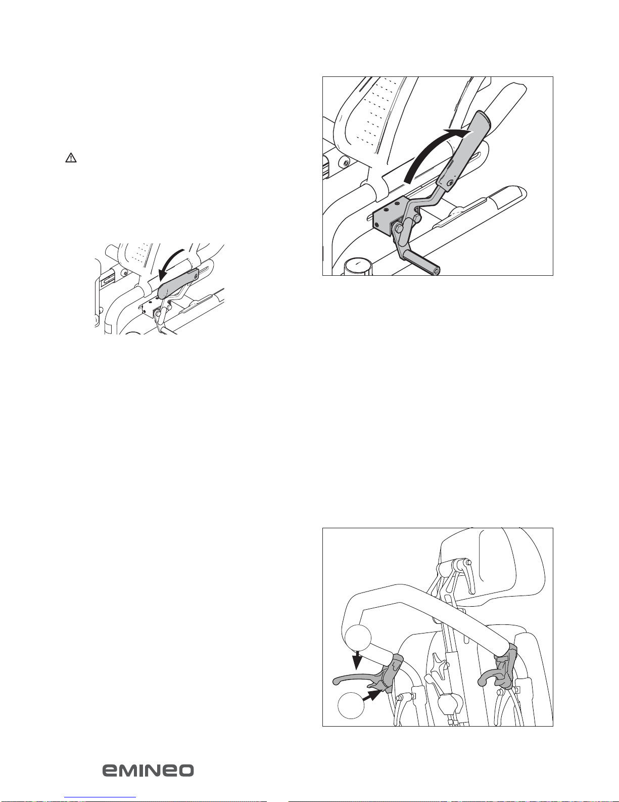
Using the brakes Figure 9
Pull the brake lever towards you to engage the
brake.
Warning!
The brake is only designed to hold the chair when
it is stationary. Under no circumstances should it
be used as a driving brake.
To make sideways transfer easier, the brake lever
can be folded down. This is done by pulling the
brake lever upwards and then folding it down.
Using the brakes on Emineo with
assistant brake Figure 10
(Assistant brake is standard on helper-guided
chairs; also available as an accessory)
• Squeeze the brake handles (18A) to brake
• Push the release handle (10B) away from you
to lock the brakes on when parking. Squeeze
the release handle to release the brakes
Figure 9
Figure 10
USING THE WHEELCHAIR

9
MB3160-EN
Figure 11
Figure 12
Anti-tip stabiliser/tipping bar Figure 11
and 12
The anti-tip stabiliser is put into position by pulling
it out and turning it in a downward direction
simultaneously. The anti-tip stabiliser is adjusted
as standard with a clearance to the base that
makes it possible to mount doorsteps etc.
The tipping bar is accessible when the anti-tip
stabiliser is up or down.
USING THE WHEELCHAIR
One-tool
Basic
10 MB3160-EN
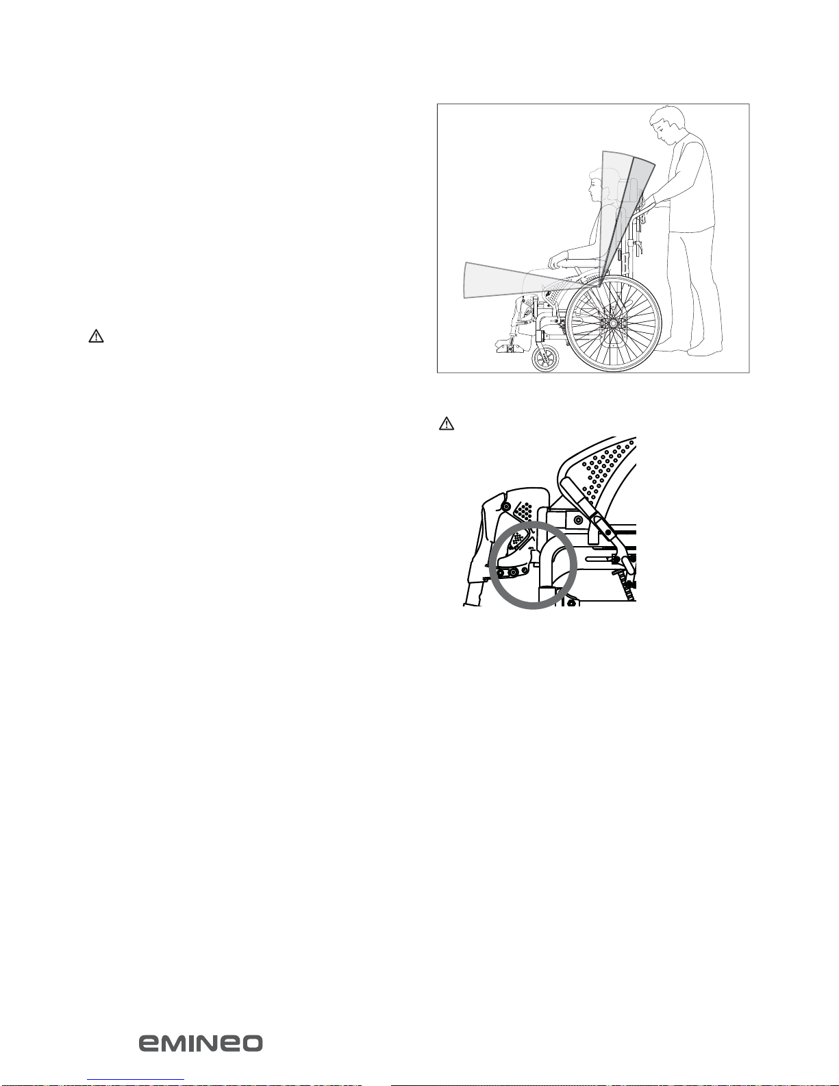
Warning: Beware of pinching!
Figure 13
Tilting Figure 13
When you tilt the chair, the balance point is
retained. As you tilt the chair backwards, the back
opens 8°. You can use various methods for tilting
the chair depending on your function level:
• The assistant squeezes the tilt lever and the
user leans forward/backward
• The assistant squeezes the tilt lever and the
user pulls himself forward/pushes himself
backward using his hands
Warning!
Beware of pinching
If a table has been fitted to the Emineo, the chair
must not be tilted with the user in it.
A user-controlled tilt lever which the user can use
without the help of an assistant, is available as an
accessory.
The balance point on Emineo can be adjusted for
optimal use in relation to the user’s function level
and weight. See page 22.
Do not put hands etc. between the side frame
and leg support attachments when tilting the
wheelchair.
USING THE WHEELCHAIR

11
A
MB3160-EN
Figure 14
Adjusting the back angle using the
adjustment lever (accessory) Figure 14
Adjust the back angle separately using the lever
(14A).
• Squeeze the lever as you push the backrest
forwards or backwards
USING THE WHEELCHAIR
Figure 15
Electrical tilt and back (accessory)
Use the manual control to tilt the chair and change
the back angle.
Charge procedure
The wheelchair must not be used during charging.
Only charge the chair when it is not in use.
Place the charger plug in the manual control and
connect to electricity (230 V). A green light will
show on the charger when the batteries are fully
charged.
It is advised to mount a smoke detector in the
charging area.
Disconnect batteries in case of longer storage
without usage.

12
A
MB3160-EN
Figure 16
Figure 17
Fold the backrest up or down
Figures 16 and 17
• Remove the armrests
• Tilt the chair forwards. Pull out the bolt (16A)
and turn it 90° to lock it in the open position,
release the bolt and fold down the back
Carry out this procedure in reverse order to pull
the back up.
USING THE WHEELCHAIR

13
MB3160-EN
Figure 18
Figure 19
Figure 20
Moving in and out of the chair
Figures 18, 19 and 20
• Activate the brakes
• Swing out or remove the leg supports
• Tilt the chair forwards
• The user can now be moved in or out the
wheelchair by means of manual lifting or a
person lift, or frontal movement if the user has
the ability to stand, see figures 18, 19 and 20.
USING THE WHEELCHAIR

14 MB3160-EN
Figure 21
Figure 22
Figure 23
Negotiating obstacles, stairs
Figures 21 and 22
If the wheelchair is being lifted up/down stairs
with the user sitting in it, the recommended lifting
points should be used. These are marked on the
product.
Warning!
Do not lift the wheelchair by the armrests.
Do not lift the wheelchair by angle adjustable leg
supports or the leg support fixation.
Note!
Make sure that the pushing handle is locked
before lifting.
In order for assistants to have a better lifting
position, they can alternatively lift from each side
of the wheelchair.
Negotiating obstacles, kerbs
Figure 23
When negotiating kerbs etc., swing the anti-tip
stabiliser up. Then place one foot on the tipping
bar whilst steering with the pushing handle. Tilt
the chair backwards where necessary to get
clearance between the obstacle and leg supports.
Steep terrain
For frequent use in undulating terrain, we
recommend that a separate brake is fitted for an
assistant where relevant.
The lifting points
are the pushing
handle, fixed leg
supports and the
side frame.
USING THE WHEELCHAIR
15
MB3160-EN
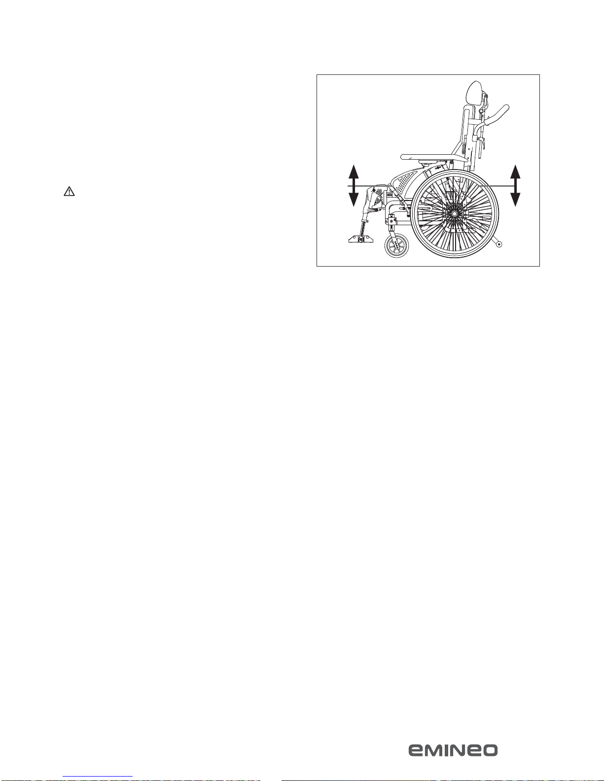
Figure 24
Adjusting the seat height
The seat height can easily be adjusted. The
different ways of adjusting the seat height also
affect the ability to negotiate obstacles and rolling
properties of the wheelchair.
Warning! Do not adjust Emineo so that you
have different seat heights at the front and back,
as this can affect the balance point.
Adjusting the seat height – back
Figure 24
The seat height at the back can be adjusted using
the methods below.
Moving the wheel block up or down
Moving the wheel block up lowers the seat.
Moving the wheel block down raises the seat. See
page 17.
Changing to bigger or smaller driving wheels
A bigger driving wheel increases the seat height,
whilst a smaller wheel decreases the height. The
table on page 38 shows which seat heights can be
achieved by changing to different sizes of driving
wheel.
Adjusting the seat height – front
Figure 24
The seat height at the front can be adjusted using
the methods below. The table on page 38 shows
which seat heights can be achieved by using the
different methods.
ADJUSTING THE WHEELCHAIR

16
A
MB3160-EN
Figure 25
Adjusting the seat height – front
• Move the bearing housing of the castor wheel
up or down (One-tool)
(see page 19)
• Moving the bearing housing up lowers the
seat, and moving it down raises the seat.
• Move the castor wheel to a higher or lower
position in the castor wheel fork
• Moving the castor wheel to a higher position
in the castor wheel fork (25A) lowers the
seat, and moving the castor wheel to a lower
position raises the seat.
Changing to bigger or smaller castor wheels
• A smaller castor wheel reduces the seat
height, whilst a bigger castor wheel increases
the seat height. By changing the castor wheel,
a smaller castor wheel will give a smaller
turning radius, and thereby increase the ability
to negotiate obstacles in narrow spaces, and
will also give more room for the legs. A larger
castor wheel will increase the turning radius
but will also improve the ability to negotiate
obstacles on uneven surfaces.
Changing to a longer or shorter castor wheel
fork
• A shorter castor wheel fork reduces the seat
height, gives a smaller turning radius, and
thereby increases the ability to negotiate
obstacles in narrow spaces, and will also give
more room for the legs. A longer castor wheel
fork increases the seat height, and allows
several alternative castor wheels to be used.
Warning! Remember to adjust the angle of
the castor wheel when you change the seat
height. Remember also to adjust the brakes when
adjusting the seat height at the back.
Castor wheel fork
Castor
wheel
Bearing
housing
ADJUSTING THE WHEELCHAIR

17
20
44
46
48
38
41,5
43,5
45,5
35
37
39
41
43
A
B
MB3160-EN
Figure 26
Figure 27
Adjusting the seat height – back
(One-tool) Figures 26 and 27
On the wheelchair frame you will find a measuring
scale (27A), which shows the seat height in
relation to the size of the driving wheel.
• Remove the driving wheel
• Loosen the nut (27B) using a 29 mm wrench
and unscrew until it stops
• Pull the inner and outer wheel block slightly
apart
• Adjust the wheel block step-by-step up or
down in accordance with the scale
• Squeeze the inner and outer wheel block
together
Note!
It is important to ensure that the pins in the wheel
block go into the holes in the frame and that
the casing lies horizontally in the track before
tightening
Find the dimension of your driving wheel at the
top of the scale. The column under the wheel
dimension shows where to place the wheel block
in order to achieve the various seat heights.
Seat heights that can
be achieved by the
different steps on the
scale
Alternative driving
wheel dimensions
ADJUSTING THE WHEELCHAIR

18
20
44
46
48
38
41,5
43,5
45,5
35
37
39
41
43
39,5
41,5
43,5
35
37
39
41
43
38
A
B
A
MB3160-EN
Figure 29
Figure 30
Figure 28
Adjusting the seat height – back
(Basic) Figure 28
• Remove the driving wheel
• Remove the wheel block by loosening the
screws (28A). Use a 4 mm Allen key to
unscrew the screws, whilst holding the nuts
using a 10 mm wrench
• Move the wheel block up for a lower seat
height, or down for a higher seat height. Refer
to the scale to find the right seat height
• Replace and tighten the screws
Adjusting the centre of gravity
(One-tool) Figures 29 and 30
The driving wheel can be moved into 5 different
positions in relation to the centre of gravity. This
is shown on a scale (29A) on the wheel block.
Position “1” represents the best anti-tipping
position.
• Loosen the nut (29B) using a 29 mm wrench,
unscrew until it stops
• Adjust the casing for the driving wheel forward
or back (Figure 30)
Note!
It is important to ensure that the pins in the wheel
block go into the holes in the frame and that
the casing lies horizontally in the track before
tightening the nut.
Warning! Remember to adjust the brakes and
the anti-tip stabiliser after you have adjusted the
seat height and centre of gravity.
Note!
When adjusting heights and the centre of gravity
you should start by adjusting the driving wheels,
followed by the height and angle of the castor
wheels.
ADJUSTING THE WHEELCHAIR

19
A
B
A
B
MB3160-EN
Figure 31
Figure 32
Figure 33
Adjusting the centre of gravity (Basic)
Figure 31
Loosen the lock nut (31A) using a 27 mm wrench,
whilst holding the casing (31B) using a 16 mm
wrench. Turn the casing (31B) 90°. Move the wheel
to the desired position. Turn the casing 90° back
and re-tighten the lock nut securely.
Warning! Remember to adjust the brakes and
the anti-tip stabiliser after you have adjusted the
seat height and centre of gravity.
Warning! If the backrest angle is configured
up to a 30° angle, the rear holes of the wheelbase
should be used in order to avoid tipping of the
chair.
Adjusting the seat height – front
Figures 32, 33 and 34
When adjusting the height of the chair, you should
adjust the height of the castor wheels before
adjusting the angle.
Adjusting the height of the castor
wheels (One-tool) Figure 33
The castor wheels have a scale from 1–8 to help
achieve the same height on both castor wheels.
• Loosen the screw (33A). Use a 5 mm Allen key
• Adjust to the desired height, see the scale
(33B)
• Re-tighten the screw
Warning! Do not adjust the height of the castor
wheels beyond the scale. The figure should be
visible in the hole on the castor wheel fastening.
ADJUSTING THE WHEELCHAIR
20
A
C
B
MB3160-EN
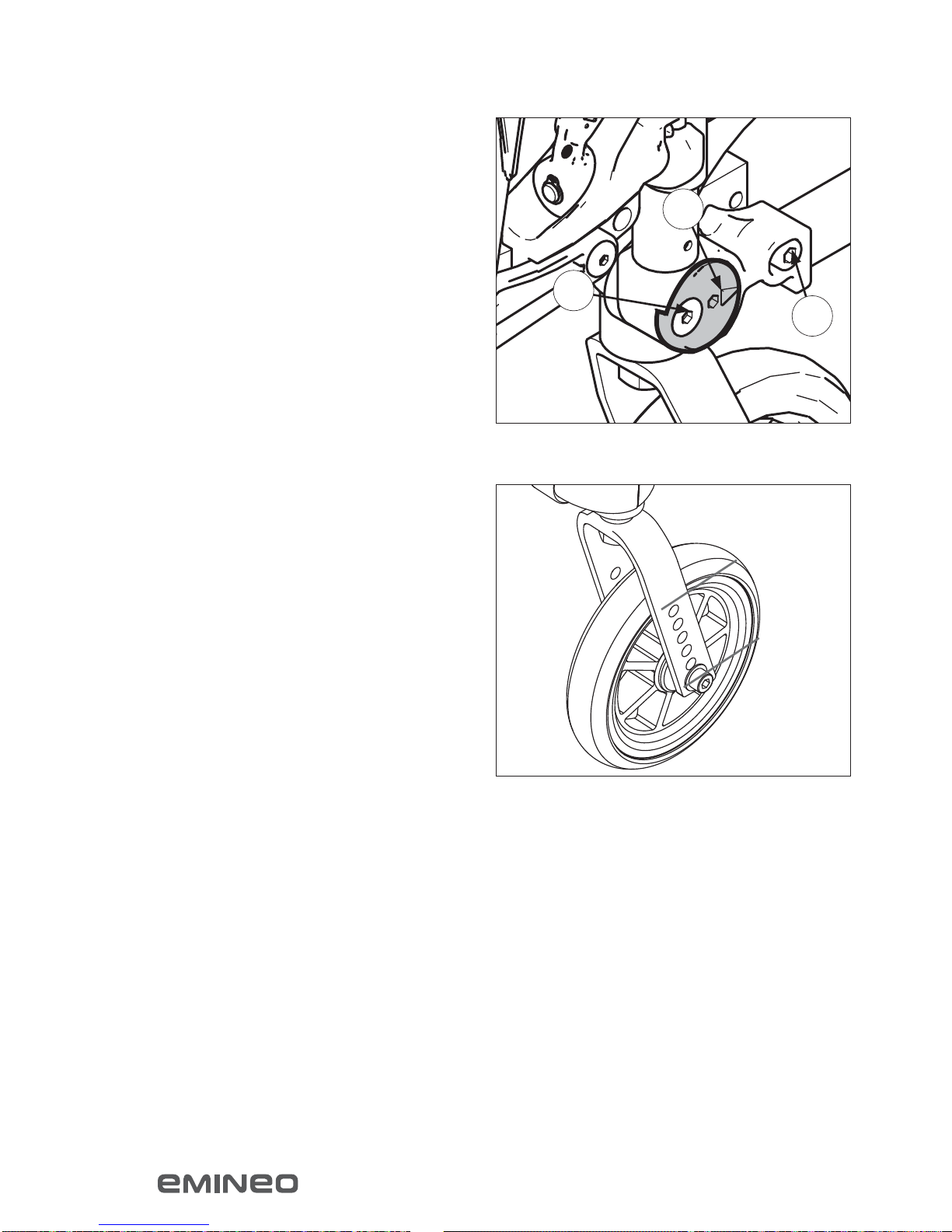
Figure 34
Figure 35
Adjusting the angle of the castor
wheels/castor angle Figure 34
• Loosen the screw (34A) slightly. Use a 5 mm
Allen key
• Loosen the screw (34B)
• Place the Allen key into the rotating disk (34C)
and rotate to the desired angle. See the scale
• Tighten the screw (34B) use a screw locking
agent such as Blue Locktite (no.243), followed
by the other screw (34A)
When the castor wheel is at the correct angle,
the bearing housing will be in a vertical position
(90°) to the base. This is achieved by using a right
angle to the bearing house/floor.
Move the castor wheel to another
position in the castor wheel fork
Figure 35
• Unscrew the screw (35A)
• Move the wheel up or down
• Tighten the screw (35A)
ADJUSTING THE WHEELCHAIR
Other manuals for Emineo
1
Table of contents
Other Breezy Wheelchair manuals


Breezy
Breezy Moonlite Manual

Breezy
Breezy UniX Manual

Breezy
Breezy Emineo User manual

Breezy
Breezy Nuage PLS User manual

Breezy
Breezy 3406015 User manual

Breezy
Breezy Breezy 90 Manual

Breezy
Breezy Relax2 Manual

Breezy
Breezy Nuage PLS User manual

Breezy
Breezy Ultra 4 Installation and operation manual

Breezy
Breezy Breezy Premium User manual


