• The wheel locks are not intended to stop your wheelchair in
motion. They are only there to ensure that your wheelchair
does not begin rolling unintentionally. When you stop on
uneven ground, you should always use the wheel locks to
prevent unintended movement. Always apply both wheel locks;
otherwise, your wheelchair could tip over.
• Explore the effects of changing the centre of gravity on the
behaviour of the wheelchair in use, for example on inclines,
slopes, all gradients or when overcoming obstacles. Do this
with the secure aid of a helper.
• With extreme settings (e.g. rear wheels in the most forward
position) and less than perfect posture, the wheelchair may tip
over even on a level surface.
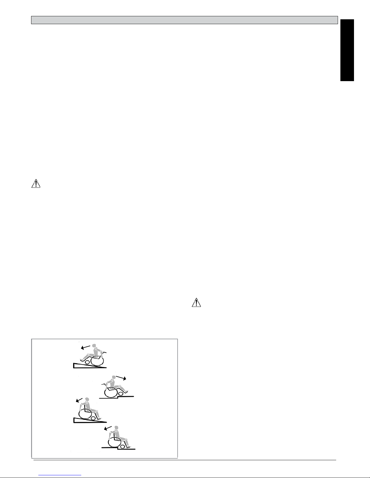
• Lean your upper body further forward when going up slopes
and steps.
• Lean your upper body further back when going down slopes
and steps. Never try to climb and descend a slope diagonally.
• Avoid using an escalator which may lead to serious injury in
the event of a fall.
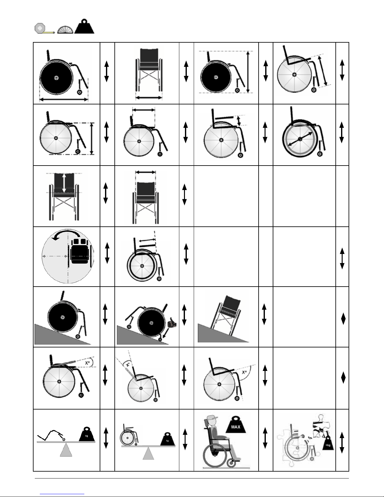
• Do not use the wheelchair on slopes more than 10°. The
Dynamic safe slope is dependant on the chair configuration,
the users abilities and the style of riding. As the users abilities
and style of riding cannot be predetermined then the max safe
slope cannot be determined. Therefore this must be
determined by the user with the assistance of an attendant to
prevent tipping. It is strongly recommended that inexperienced
users have Anti-tips fitted.
• It is possible that potholes or uneven ground could cause this
wheelchair to tip over, especially when riding uphill or downhill.
• Do not use your wheelchair on muddy or icy ground.
• Do not use your wheelchair where pedestrians are not allowed.
• To avoid hand injuries do not grab in between the spokes or
between the rear wheel and wheel lock when driving the
wheelchair.
• In particular when using lightweight metal handrims, fingers will
easily become hot when braking from a high speed or on long
inclines.
• Only attempt stairs with the help of an attendant. There is
equipment available to help you, e.g. climbing ramps or lifts,
please use them. If there is no such equipment available, then
the wheelchair must be tipped and pushed, never carried, over
the steps (2 helpers). We recommend that users over 100 kg in
weight are not transferred in this way. In general, any anti-tip
tubes fitted must be set beforehand, so that they cannot touch
the steps, as otherwise this could lead to a serious tumble.
Afterwards the anti-tip tubes must be set back to their correct
position.
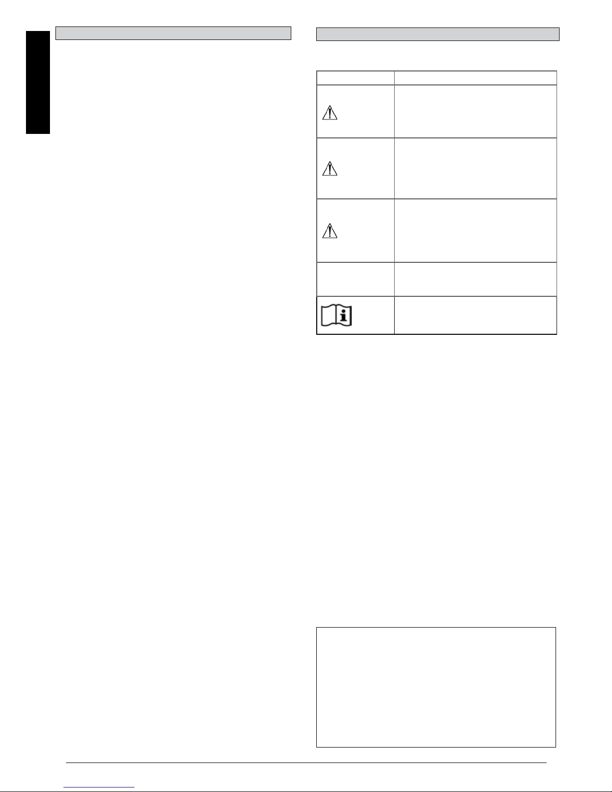
DANGER!
• Make sure that the attendant only holds the wheelchair using
securely mounted parts. Do not use removable parts (e.g. not
on the footrests or the side guards).
• When using the lifting ramp make sure that the anti-tip tubes
fitted are positioned outside the danger area.
• Secure your wheelchair on uneven ground or when
transferring, e.g. into a car, by using the wheel locks
• When using the lifting ramp make sure that the anti-tip tubes
fitted are positioned outside the danger area.
• Secure your wheelchair on uneven ground or when
transferring, e.g. into a car, by using the wheel locks.
• If and whenever possible, during a journey in a specially fitted
vehicle for disabled people, vehicle occupants should use the
seats in the vehicle and the appropriate restraint system. This
is the only way to ensure that occupants will have the
maximum protection if there is an accident.
• Depending on the diameter and setting of the castors, as well
as the centre of gravity setting of the wheelchair, the castors
may begin to wobble at high speeds. This can lead to castor
seizure and the wheelchair may tip over. Therefore, please
make sure that the castors are adjusted correctly (see the
Chapter "Castors").
General safety notes and driving restrictions
The engineering and construction of this wheelchair has been
designed to provide maximum safety. International safety
standards currently in force have either been fulfilled or
exceeded in parts.
Nevertheless, users may put themselves at risk by improperly
using their wheelchairs. For your own safety, the following rules
must be strictly observed.
Unprofessional or erroneous changes or adjustments increase
the risk of accident. As a wheelchair user, you are also part of
the daily traffic on streets and pavements, just like anyone else.
We would like to remind you that you are therefore also subject
to any and all traffic laws.
Be careful during your first ride in this wheelchair. Get to know
your wheelchair.
Before each use, the following should be checked:
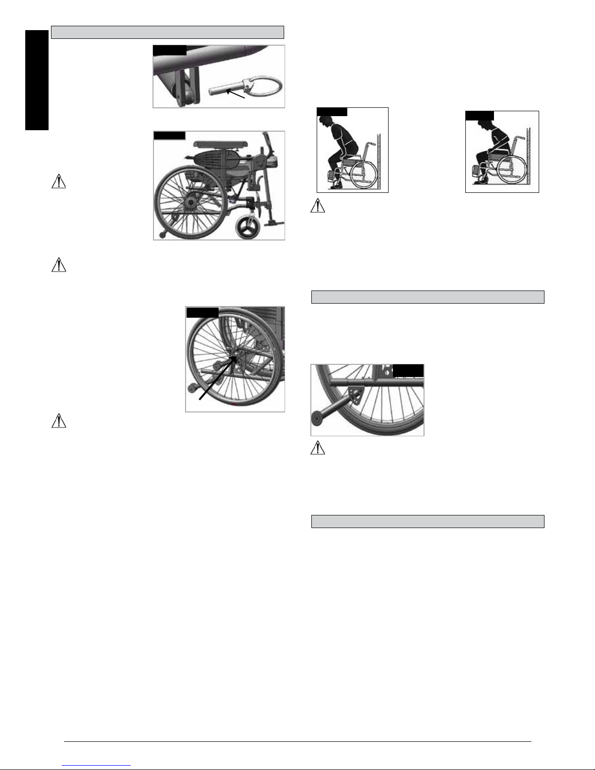
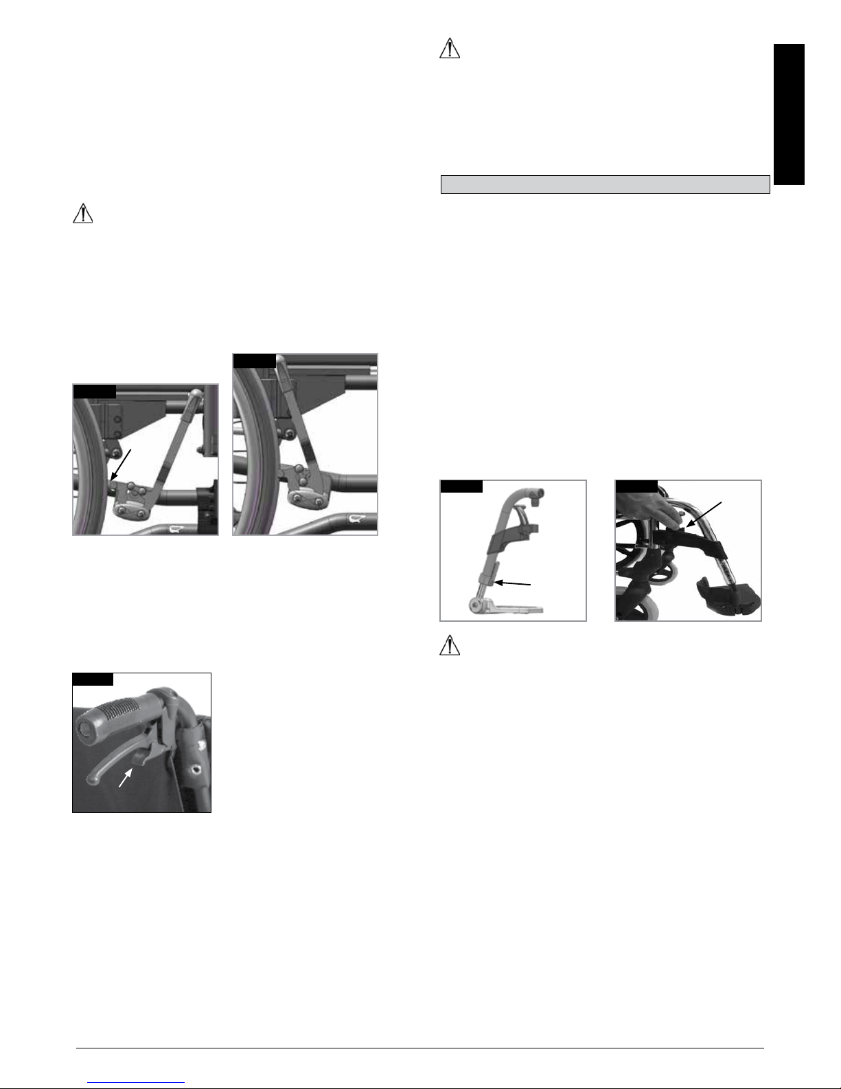
• Fixed axles or Quick-release axles on the rear wheels.
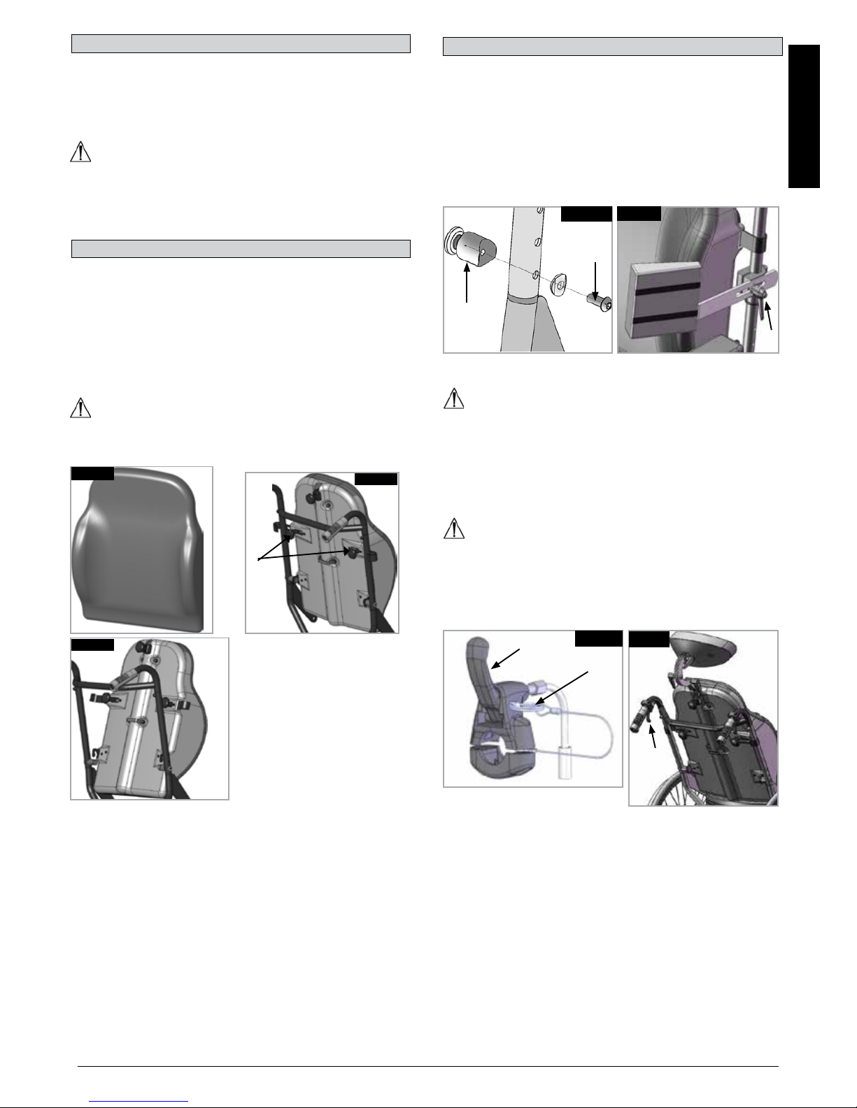
• Velcro on seats and backrests
• Tyres, tyre pressure and wheel locks.
Before changing any of the adjustments of this wheelchair, it is
important to read the corresponding section of the user’s
manual.
It is possible that potholes or uneven ground could cause this
wheelchair to tip over, especially when riding uphill or downhill.
When riding forwards over a step or up an incline, the body
should be leaning forward.
DANGER!
• NEVER exceed the maximum load of 145 kg, (XL=170 kg), for
user plus any items carried on the wheelchair. If you exceed
the maximum load, this can lead to damage to the chair, or you
may fall or tip over, lose control and may lead to serious injury
of the user and other people.
• When it is dark, please wear light clothing or clothing with
reflectors, so that you can be seen more easily. Make sure that
the reflectors on the side and back of the wheelchair are clearly
visible.
• We would also recommend that you fit an active light.
• To avoid falls and dangerous situations, you should first
practice using your new wheelchair on level ground with good
visibility.
• When getting on or off the wheelchair, do not use the
footboards.
• These should be flipped up beforehand and swung to the
outside as far as possible. Always position yourself as close as
possible to the place where you wish to transfer to.
• Only use your wheelchair with care. For example, avoid
travelling against an obstacle without braking (step, kerb edge)
or dropping down gaps.
10°
10°