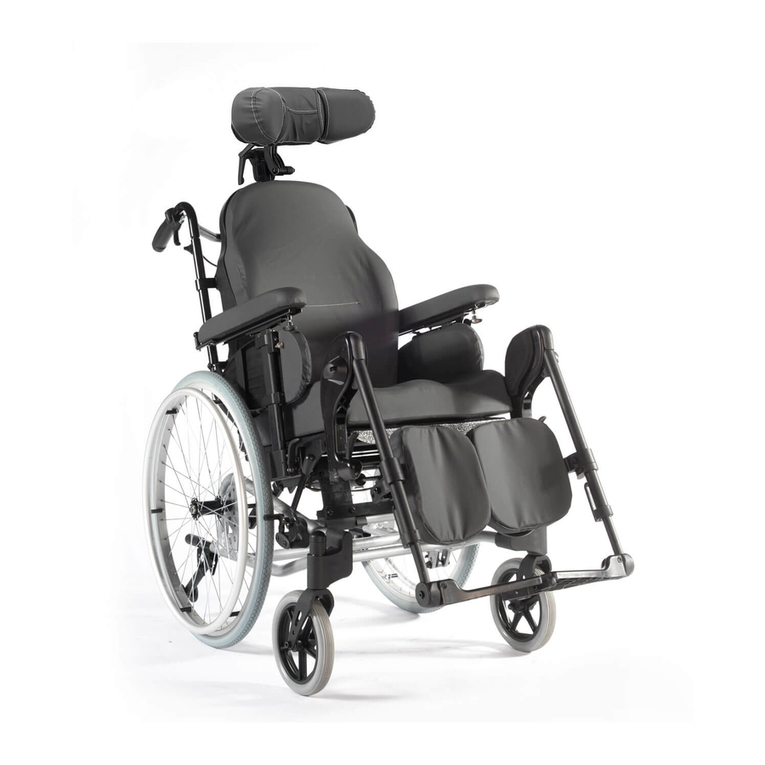
Breezy Elegance Manual

Elegance
Directions for use
Gebrauchsanweisung
Notice D’Utilisation
Manuale Per l’Uso
Manual De Usario


BREEZY ELEGANCE · Rev.A 3
EENNGGLLIISSHH
Foreword (1.1.1) Table of Contents
Dear Customer,
We are very happy that you have decided in favour of a high-quali-
ty product from SUNRISE MEDICAL. This user’s manual will pro-
vide numerous tips and ideas so that your new wheelchair can
become a trustworthy and reliable partner in your life.
Maintaining close links with our customers is of great importance
to us at Sunrise Medical: we therefore like to keep you up-to-date
with the latest developments at Sunrise Medical. Keeping close to
our customers also means fast service when you need replace-
ment parts or accessories, or just have a question about your
wheelchair – and with as little red tape as possible.
We want you to be satisfied with our products and service. Sunrise
Medical therefore constantly works to continuously develop its
products. For this reason, changes can occur in our range of pro-
ducts with regard to shape, technology and fittings. Consequently,
no claims can be construed from the data or pictures contained in
this user’s manual.
SUNRISE MEDICAL has been awarded the ISO- 9001 Certificate,
which affirms the quality of our products at every stage, from R & D
to production.
Please contact your local, authorised SUNRISE MEDICAL dealer if
you have any questions concerning the use, maintenance, or
safety of your wheelchair.
In the case that there is no authorised dealer in your area or you
have any questions, you can contact Sunrise Medical either in
writing or by telephone at:
Sunrise Medical GmbH
High Street Wollaston
West Midlands DY8 4PS
England
Phone +44 (0) 1384 446622
Fax +44 (0) 1384 446644
www.sunrisemedical.com
Foreword . . . . . . . . . . . . . . . . . . . . . . . . . . . . . . . . . . . . . . . . . . . . .3
Safety Tips . . . . . . . . . . . . . . . . . . . . . . . . . . . . . . . . . . . . . . . . . . . .4
Wheelchair components . . . . . . . . . . . . . . . . . . . . . . . . . . . . . . . . .5
Handling . . . . . . . . . . . . . . . . . . . . . . . . . . . . . . . . . . . . . . . . . . . . .6
Options
Step Tubes . . . . . . . . . . . . . . . . . . . . . . . . . . . . . . . . . . . . . . . . . . .6
Brakes . . . . . . . . . . . . . . . . . . . . . . . . . . . . . . . . . . . . . . . . . . . . . . .6
Footplate . . . . . . . . . . . . . . . . . . . . . . . . . . . . . . . . . . . . . . . . . . . . .7
Castors . . . . . . . . . . . . . . . . . . . . . . . . . . . . . . . . . . . . . . . . . . . . . .7
Axle Plates . . . . . . . . . . . . . . . . . . . . . . . . . . . . . . . . . . . . . . . . . . . .7
Backrest . . . . . . . . . . . . . . . . . . . . . . . . . . . . . . . . . . . . . . . . . . . . .7
Armrest . . . . . . . . . . . . . . . . . . . . . . . . . . . . . . . . . . . . . . . . . . . . . .8
Lap belt instructions . . . . . . . . . . . . . . . . . . . . . . . . . . . . . . . . . . . .8
Anti-Tip Tubes . . . . . . . . . . . . . . . . . . . . . . . . . . . . . . . . . . . . . . . . .9
Seat . . . . . . . . . . . . . . . . . . . . . . . . . . . . . . . . . . . . . . . . . . . . . . . . .9
Crutch Holder . . . . . . . . . . . . . . . . . . . . . . . . . . . . . . . . . . . . . . . . .9
Travel Wheels . . . . . . . . . . . . . . . . . . . . . . . . . . . . . . . . . . . . . . . . .9
Tyres and Mounting . . . . . . . . . . . . . . . . . . . . . . . . . . . . . . . . . . . . .9
Possible Problems . . . . . . . . . . . . . . . . . . . . . . . . . . . . . . . . . . . . . .9
Maintenance and Care . . . . . . . . . . . . . . . . . . . . . . . . . . . . . . . . .10
Technical Data . . . . . . . . . . . . . . . . . . . . . . . . . . . . . . . . . . . . . . . .10
Nameplates / Guarantee . . . . . . . . . . . . . . . . . . . . . . . . . . . . . . . .10
Torque . . . . . . . . . . . . . . . . . . . . . . . . . . . . . . . . . . . . . . . . . . . . . .10
This manual gives information on all features sold across different
countries, without stating whether they are actually available in
your country or are optional or standard features. For this informa-
tion please refer to the orderform/prescription form or your
prescriber/supplier.

4BREEZY ELEGANCE · Rev.A
EENNGGLLIISSHH
Safety Tips (3.1.2)
The engineering and construction of this wheelchair have been
designed to provide maximum safety. International safety stan-
dards currently in force have either been fulfilled or exceeded. Ne-
vertheless, users may put themselves at risk by improperly using
their wheelchairs. For your own safety, the following rules must
absolutely be observed. Unprofessional or erroneous adaptation or
adjustment work could increase the risk of accidents. As a wheel-
chair user, you are also part of the daily traffic on streets and side-
walks, just like anyone else. We would like to remind you that you
are thus also subject to any and all traffic laws. For this reason, you
should always wear light clothing in the dark as much as possible
so that you can be seen more easily and make sure that the reflec-
tors are not covered. Be careful during your first ride in this wheel-
chair. Get to know your wheelchair. Test what effect changing the
center of gravity would have on your wheelchair. Practice using
your wheelchair on level ground as well as going uphill and downhill.
CAUTION:
The wheel locks are not intended to brake your wheelchair. They
are only there to ensure that your wheelchair does not begin rolling
unintentionally. When you stop on uneven ground, you should
always use the wheel locks to prevent such rolling. Always set both
wheel locks; otherwise, your wheelchair could tip over.
The wheel locks have not been designed to be used as brakes
for a moving wheelchair.
Always make use of elevators and ramps. If these are not available,
you can reach your destination with the aid of two attendants.
They should grip the wheelchair at securely mounted parts. If
your wheelchair is equipped with anti-tip tubes, these should be
folded away. A wheelchair should never be lifted with an occupant;
it should only be pushed.
Before each use, the following should be checked:
• Quick-release axles on the rear wheels
• Velcro on seats and backrests
• Tyres, tyre pressure, and wheel locks.
Wheel locks will not function properly if tyre pressure is too
low or the interval between tyres and wheel locks is too large.
The maximum user weight is 125 kilograms (20 stone).
This wheelchair should be used exclusively to convey one person
at a time in the seat. Any other use beyond this limit is in violation
of safety regulations.
Users should not sit in the wheelchair while riding in any and
all means of transportation.
Only permanently installed seats and seat belts will offer sufficient
protection in hazardous situations. When vehicles are in motion,
unoccupied wheelchairs should be secured using appropriate
means. Before changing any of the adjustments of this wheelchair,
it is important to read the corresponding section of the user
manual. It is possible that potholes or uneven ground could cause
this wheelchair to tip over, especially when riding uphill or downhill.
When riding over a step or up an incline frontally, the body should
be leaning forward.
Transportability of wheelchairs and users in
vehicles
A wheelchair secured in a vehicle will not provide the equivalent
level of safety and security of a vehicle seating system. It is always
recommended that the user transfers to the vehicle seating. It is
recognised that this is not always practical for the user to be trans-
ferred and in these circumstances where the user must be trans-
ported whilst in the wheelchair the following advice should be followed.
1. Confirm that the vehicle is suitably equipped to transport a pas-
senger in a wheelchair and has access that is suitable for your
wheelchair type.
2. Sunrise Medical Ltd recommends:
a) That the wheelchair be secured by a 4-part (webbing) Tie Down
Restraint system, conforming to ISO 10542. These restraints
generally comprise of 4 individual straps that are attached to
each corner of the wheelchair
b) That the occupant should be restrained independently of the
wheelchair by a lap and diagonal safety belt, conforming to ISO
10542. This is similar to a car seat belt that comes across the
user’s shoulder and around the waist.
c) Any part of the wheelchair
accessories such as kerb clim-
bers) that can easily be deta-
ched should be removed and
stored in the vehicle luggage
compartment during transporta-
tion.
d) The wheelchair should always
be transported in the forward
facing direction.
e) Sufficient space should be avai-
lable around the wheelchair to
enable clear access to attach,
tighten and release the wheel-
chair and occupant tie down
restraints and safety belts.
f) User should be provided with a
headrest that is suitable for use
with the wheelchair in transpor-
tation.
g) The tie-down restraints should
be fitted to the main frame of
the wheelchair as indicated in
the diagram on the following
page, and not to any attachments or accessories, e.g. not aro-
und the spokes of wheels, brakes or footrests.
h) The tie–down restraints should be attached as close as possible
at an angle of 45 degrees and tightened securely in accordance
with the manufacturer's instructions.
i) Pelvic restraint, posture belts or lap belts supplied with the
wheelchair should always be used in addition to, but never as a
substitute for the approved passenger restraint belts.
j) The safety of the user during transportation depends upon the
diligence of the person securing the tie-down restraints and they
should have received appropriate instructions and/or training in
their use.
The wheelchair should be restrained with 4-point tie down
webbing straps, with non-adjustable front straps and adju-
stable rear straps, which typically use Karabiner clips/S
hooks and tongue and buckle attachments.
The attachment points to the chair are the inner front side
frame just above the castor and the rear side frame. The
straps are fitted around the side frames at the intersection of the
horizontal and vertical frame tubes. (See illustration on following page)
The tie down symbol on the wheelchair frame indicates the positi-
on of the wheelchair restraint straps. The straps are then tensioned
after the front straps have been fitted to secure the wheelchair.
The wheelchair must be facing forward and the manual brakes
firmly applied. The wheelchair occupant should be secured using a
3-point double inertia reel belt.
It is recommended that a lap/pelvic belt similar to the example
shown previously in the section headed seat belts, be used in con-
junction with the vehicle occupant restraints.
The seat/pelvic belt should never be used in place of the occu-
pant lap and diagonal belt when travelling in a vehicle.
Transportability – positioning of wheelchair tie
down restraints on wheelchair
Position of the front
wheelchair tie down
restraint and the tie
down label. The posi-
tion is the same for
both the Breezy Ele-
gance self-propelling
and the attendant
push wheelchairs.
Position of the rear
wheelchair tie down
restraint and the tie
down label on the
self-propelling
wheelchair.
Position of the rear
wheelchair tie down
restraint and the tie
down label on the
attendant push
wheelchair.

BREEZY ELEGANCE · Rev.A 5
EENNGGLLIISSHH
Wheelchair components (4.1.1)
We at SUNRISE MEDICAL have been awarded the ISO 9001
Certificate, which affirms the quality of our products at every stage,
from R & D to production. This product meets relevant National
and International Standards to satisfy compliance with EU
directives. Optional equipment and accessories are available at
extra charge.
Wheelchairs:
1. Push handles
2. Backrest upholstery
3. Sideguards
4. Seat sling
5. Footrest
6. Castors
7. Quick-release axles
8. Wheel locks
9. Handrim
10. Rear wheel
2
8
10
6
5
3
7
1
9
4

6BREEZY ELEGANCE · Rev.A
EENNGGLLIISSHH
Handling
Folding up (6.1)
First remove the seat cushion from
the wheelchair and flip up the
(platform) footplate or the individu-
al footplates. Take hold of the sling
from underneath in the middle and
pull upwards. The wheelchair will
then fold up. To fold your
wheelchair until it is as small as
possible, e.g., to put into a car, you
can remove the footrests (depend-
ing on the model). For this purpo-
se, open the latch from the outside
and swing the footrest to the side.
Then the footrest only has to be dra-
wn out of the frame tubing.
Unfolding
Press down on the seat tubing (see
picture). Your wheelchair is then
unfolded. Now snap the seat tubing
into position in the seat saddle. This
can be facilitated by slightly tipping
your wheelchair. In this way, the
weight can be taken off of one rear
wheel so that the wheelchair can
be more easily unfolded. Be careful not to get your
fingers caught in the cross-tube assembly.
Options – Step Tubes
Step Tubes (7.1)
Step tubes are used by attendants
to tip a wheelchair over an
obstacle. Simply step on the tube
to push a wheelchair, for example,
over a kerb step.
02.1
Options – Brakes
Wheel Locks (7.10)
Your wheelchair is equipped with
two wheel locks. They are applied
directly against the tyres. To
engage, press both wheel-lock
levers forward against the stops
(Fig. 1 and 2). To release the wheel,
pull the levers back to their original
positions.
Braking power will decrease with:
• Worn tyre tread
• Tyre pressure that is too low
• Wet tyres
• Improperly adjusted wheel locks.
The wheel locks have not been
designed to be used as brakes for
a moving wheelchair. The wheel
locks should therefore never be
used to brake a moving
wheelchair. Always use the hand-
rims for braking. Make sure that
the interval between the tres and
wheel locks complies with given
specifications (Fig. 1 and 2
)
. To
readjust, loosen screw (1) and set
the appropriate interval. Tighten
screw (see the page on torque)
CAUTION:
After each adjustment of the rear wheels, check
the interval to the wheel locks and readjust if
necessary.
02.2
Extension for the wheel lock
Lever (7.11)
The longer lever helps to minimise
the effort needed to set the wheel
locks.
CAUTION:
Mounting the wheel lock too
close toward the wheel will
result in a higher effort to
operate. This might cause the
wheel lock extension lever to
break!
Leaning onto the wheel lock extension lever while
transferring will cause the lever to break! Splashing
water from tyres might cause the wheel lock to
malfunction.
Quick-Release Axles
for Rear Wheels (6.2)
The rear wheels are equipped with
quick-release axles. The wheels
can thus be installed or removed
without using tools. To remove a
wheel, simply depress the quick-
release button on the axle (1) and
pull it out.
CAUTION:
Hold the quick-release button on
the axle depressed when inser-
ting the axle into the frame to mount the rear
wheels. Release the button to lock the wheel in
place. The quick-release button should snap
back to its original position.
Drum Brakes (7.13)
Drum brakes permit safe and
convenient braking for an
attendant. They can also be set
with the aid of a locking lever (1) to
prevent rolling. This lever must
snap audibly into place. Drum
brakes are not dependent on the
aid of air pressure inside the tires.
Your wheelchair cannot be moved
when the drum brakes are set.
CAUTION:
Drum brakes should only be adjusted by
authorized dealers.
403
400
1
401
402.1 1
402.2 2
1
3 mm
404
1

BREEZY ELEGANCE · Rev.A 7
EENNGGLLIISSHH
Options – Footplate
Footrest (7.21.3)
The footrests can be flipped up to
make it easier to get into and out
of the chair. By loosening the
screw (1) the angle can be ad-
justed in the area of ± 15°. Then
re-tighten the screw (see Torque).
Lower leg length
By loosening the screw (1) the
lower leg length can be adjusted.
Loosen the screws and adjust the
tube with the footrest to the desi-
red position. Then re-tighten the
screw (see page on Torque). Make
sure that the gap to floor is not
below the minimum of 2.5 cm.
Legrests and Latch (7.23.1)
The legrest can be swung in and
outwards.
Fit your legrest by inserting it with
the footplate(s) pointing toward the
outside. Then rotate it toward the
inside until it locks into place (1).
To remove the legrest, depress the
lever (2), swing the footrest towards
the outside and lift to remove it.
Make sure that the legrest is pro-
perly locked into place.
CAUTION:
The legrests should not be used to lift or to carry
the wheelchair.
Elevating legrest (7.24.1)
To elevate:
Lift your lower leg and press the release button. Pull
the legrest upwards and adjust it
to the desired height. As soon as
you release the button, the legrest
will click back into place.
To lower:
Lift your lower leg and press the
release button to unlock the
legrest to lower it (1). As soon as
you release the button, the legrest
will click back into place.
CAUTION:
The elevating legrest is not
allowed to be adjusted into the
lowest position to avoid any interference with
the castors.
CAUTION:
Keep hands clear of the adjustment mechanism
between the frame and the movable parts of the
legrest while elevating or lowering the legrest.
CAUTION:
Legrests are not to be used for lifting or carrying
the wheelchair with an occupant.
Options – Castor
Adjustment of seat height and seat angle
(7.51.1.3)
By loosening the screws (1, 2) you can adjust
the appropriate chair angle.
Adjust the castor so that, as far as possible,
the axle is at 90° to the floor. After adjustment,
all the screws must be re-tightened (see the
page on Torque).
The front seat height can also be adjusted by
altering the castor in the castor fork (Seat
heights 47, 50, 52 cm) and by altering the
castor connector (Seat height 42, 45 cm).
For detailed adjustability possibilites, please
see figure 1 and figure 2 on page 10.
Options – Axle Plates
Horizontal Axle Position(7.51.1.2)
The axle plate can be positioned
forward for maximum maneuver-
ability or rearward for increased
stability.
CAUTION:
Wheel locks must be adjusted to
suit the new position.
The longer the wheel base, the
greater the stability of the
wheelchair. Turn the axle bracket
to the rear (1) in order to extend the wheel base.
CAUTION: Wheel locks must be adjusted to suit
the new position.
Options – Backrest
Adjustable back height (7.77.3)
The backrest can be set to two
different back heights (41-43 cm).
Undo the screws (1) and adjust the
back to the required height.
Tighten the screws back up (see
Torque).
Half folding backrest (7.78)
For folding the back down press
the latches (1).
CAUTION:
Make sure that the backrest
locks in correctly when it is set
upright again. When adjusting be
careful not to get your fingers
caught.
405
1
408
1
2
409
1
Adjustable Backrest
Upholstery
The sling can be adapted to any
degree of tension by adjusting the
Velcro fasteners. The padding in
the backrest can be removed
through an interior opening, allo-
wing you to cushion the backrest
according to your individual needs.
416.3
1
406 a
1
407 a
2
1
410
1
410.1
1

8BREEZY ELEGANCE · Rev.A
EENNGGLLIISSHH
Options – Armrest
Standard sideguard, flip-up,
removable with short or long
arm pads (7.81.3)
With the sideguard which is
stepped down at the front it is
possible to move up closer to a
table. To flip them up press the
lever (1) forwards, so that the side-
guard is released.
ATTENTION!
Sideguards, and the armrests
are not designed to be used to
lift or carry the wheelchair.
Sideguard, flip-up, removable
with short or long arm pads,
height-adjustable
The arm pad can be height-adjust-
ed in the following way. Push the
lever (1) and adjust the arm pad (2)
to the desired height. Release the
lever and push the arm pad (2)
down until you hear it click into
place.
ATTENTION!
Sideguards, and the armrests
are not designed to be used to lift or carry the
wheelchair.
411.2
1
2
411
1
Options – Lap belt instructions
Note:
Lap belts are fitted as positional
aids, and are not suitable as trans-
portation restraints.
Step 1
Positioning belt kit. The Positioning
belt kit contains, one positioning
belt, three tri glide buckles and two
cable ties.
Step 2
To assemble the positioning belt.
Take the positioning belt strap and
thread through the tri-glide. Repeat
on both ends of positioning belt.
Step 3
To fit the positioning belt to the
chair. Take the positioning belt
strap and wrap around back post.
Step 4
Thread the positioning belt back
through the tri-glide to form a loop
around the back post. Thread
positioning strap through tri-glide
as shown in step 5.
Step 1
Step 2
Step 3
Step 5
Step 6
Step 7
Step 8
Tri-glides
Fastening buckle
The positioning belt can be used on the Quickie RXS, Quickie 2,
Breezy SLTL and Quickie 2 Millennium wheelchairs.
Advice to client
The positioning belt must only be fitted by an approved Sunrise
Medical dealer / agent. The positioning belt should only be adju-
sted by a professional, or a Sunrise Medical approved dealer /
agent.
The positioning belt must be checked on a daily basis to ensure
they are adjusted correctly (see step 7) and are free from any
obstruction or adverse wear.
Sunrise Medical does not encourage the transportation of any per-
son in a vehicle using this positioning belt as a method of restraint.
Please see Sunrise Medical transit booklet for further advice on
transportation.
Maintenance:
Check lap belt, and securing components, at regular intervals for
any sign of frays, or damage. Replace if necessary.
NOTE:
The lap belt should be adjusted to suit the end user as
detailed above. Sunrise Medical recommend that the
length and fit of the belt be checked on a regular basis to
reduce the risk of the end user inadvertently re-adjusting
the belt to an excessive length.
Quickie RXS
Quickie 2Breezy SL/TL
Quickie 2
Millennium
Step 4
Step 5
To secure the positioning belt to
the chair. Take one of the cable ties
supplied and thread through the
positioning belt strap. Then wrap
around the frame and fasten
together. DO NOT over tighten
positioning belt. Repeat steps 3-5
with both ends of positioning belt.
Step 6
To adjust the positioning belt
use the tri-glide buckles and the
fastening buckle.
Step 7
The positioning belt should be
adjusted so the fastening buckle
is situated in the middle of the
pelvis.
Step 8
The positioning belt should be
adjusted so a hand can be placed
between the user and the belt.

Options – Anti-Tip Tubes
Anti-tip tubes (7.93.1)
The anti-tip tubes provide additional
safety for inexperienced users when
they are still learning how to operate
their wheelchairs. Anti-tip tubes pre-
vent a wheelchair from tipping over
backwards. By pulling the interlock (1),
the anti-tip tube can be height adjust-
ed. There should be a gap of 2,5 cm to
the floor. To go up or down a step (e.g.
kerb) the anti-tip tubes must be swung
upwards, to prevent them from touch-
ing the ground.
Options – Crutch Holder
Crutch Holder (7.110)
This device permits crutches to be transported directly on a
wheelchair. It has a Velcro loop (1) to fasten crutches or other aids.
CAUTION:
Never try to use or even remove the crutches or other aids
while moving.
Options – Seat
Standard seat sling (7.101.1)
The seat sling has Velcro®fastening on each side.
This makes it possible to re-tension it easily. To re-
tension the seat sling, fold the wheelchair slightly.
Remove the screws (1).
By opening the Velcro®fastening the seat sling can
now be re-adjusted. To re-assemble, follow the
procedure in reverse order. Make sure that after the
adjustment work, all screws are re-tightened (see
page on Torque).
ATTENTION!
In order to ensure safety, at least 50% of the
Velcro®surface must be in contact.
Seat depth (7.102.2)
By loosening the screws (1) the
position of the seat sling can be
changed and therefore the seat
depth can be altered. Re-tighten
the screws afterwards (see
Torque).
Options – Travel Wheels
Travel Wheels (7.113)
Travel wheels should be used wherever your wheelchair would be
too wide if the rear wheels were used (e.g., in airplanes, buses,
etc.). After the rear wheels have been removed with the aid of the
quick-release axles, the transit wheels can immediately be used to
continue riding. The transit wheels are mounted so that they are
approx. 3 centimeters above the ground when not in use. They are
thus out of the way when riding, transporting, or when tipping to
pass over obstacles (e.g., kerbs, steps, etc.).
CAUTION:
Your wheelchair does not have any wheel locks when the tran-
sit wheels are being used.
414
1
413 a
1
BREEZY ELEGANCE · Rev.A 9
EENNGGLLIISSHH
Possible Problems
Tyres and Mounting
Tyres and Mounting (8.1)
Always make sure you that you maintain the correct tyre pressure,
as this can have an effect on wheelchair performance. If the tyre
pressure is too low, rolling resistance will increase, requiring more
effort to move the chair forward. Low tyre pressure also has a
negative impact on maneuverability. If the tyre pressure is too high,
the tyre could burst.
The correct pressure for a given tyre is printed on the surface of
the tyre itself.
Tyres can be mounted the same way as an ordinary bicycle tyre.
Before installing a new inner tube, you should always make sure
that the base of the rim and the interior of the tyre are free of for-
eign objects. Check the pressure after mounting or repairing a tyre.
It is critical to your safety and to the wheelchair’s performance that
regulation air pressure be maintained and that tyres be in good
condition.
Wheelchair pulls to one side (9.1.1)
• Check tyre pressure
• Check to make sure wheel turns easily
(bearings, axle)
• Check to make sure both castors are making
proper contact with the ground
Castors begin to wobble (9.2.1)
• Check to make sure all bolts are secure; tighten if necessary (see
the page on torque)
• Check to make sure both castors are making proper contact
with the ground
Wheelchair / Cross-tube assembly does not snap into position
in the seat saddle (9.3)
• Chair is still new, i.e., the seat or backrest upholstery is still very
stiff. This will improve with continued use.
Wheelchair is difficult to fold up (9.5.1)
• Screws of the cross-tube brackets are too tight.
Wheelchair squeaks and rattles (9.6)
• Check to make sure bolts are secure; tighten if necessary (see
the page on torque)
• Apply small amount of lubrication to spots where movable parts
come in contact with one another
Wheelchair begins to wobble (9.7.1)
• Check tyre pressure.
• Check to see if rear wheels are adjusted differently.

10 BREEZY ELEGANCE · Rev.A
EENNGGLLIISSHH
Torque (12.1.1)
Nameplates / Guarantee
Rating plate (11.1.3)
The rating plate is located on the cross-brace tube or
cross-frame tube and also on the back of the user guide.
This plate gives the exact type descriptions as well as other
technical information. When ordering spare parts or making
a complaint please give the following information
• Serial number
• Order number
• Month/Year
Guarantee
You have purchased a high-quality Breezy product. As a
sign of our gratitude, we are providing you with a 5-year
guarantee on all frame components and the cross-tube
assembly as well as 2 years on all other parts. We take no
responsibility for any damage resulting from inappropriate
or unprofessional assembly and/or repairs, through neglect
and wear and tear, as well as any alterations to wheelchair
components by the user or by any third party. In such
cases, our product responsibility is voided.
Custom wheelchairs cannot be exchanged.
The torque for the screws shown:
10 Nm castor and axle adapter screws must be secured with
Loctite again after they have been loosened.
The torque for all screws is 7 Nm.
415.1 415.2
416.2 2
Breezy Elegance settings
Position of per- Position Adjustment Adjustment Front Seat
forated plate of caster of caster of caster Seat Angle
on rear wheel fork fork A fork B Height
5 Y3 P2 F4/F2 42cm 0°
6 Y3 P3 F4/F3 43cm 3°
4 Y3 P5 F5/F2 47cm 3°
4 Y2 P6 F5/F3 47cm 6°
3 Y2 P5 F5/F2 49cm 3°
1 Y1 P5 F5/F2 51cm 0°
2 Y1 P5 F5/F2 51cm 3°
416.1 1
Technical Data (10.300)
Total width:
• With standard wheels including handrims, narrow fitting:
Seat width + 19,5 cm
• With drum brake wheels, handrims, narrow fitting:
Seat width + 20 cm
Folded dimensions:
• With standard wheels: approx. 33 cm
• Without standard wheels: approx. 17 cm
Weight in kg:
• Wheelchair 16 kg
• Footrest (pair) 1.5 kg
• Standard sideguard 1.8 kg
• 24” rear wheel (solid) 1.4 kg
Maximum load:
Approved to loads up to 125 kg (20 stone)
Maintenance and Care
Maintenance (9.9)
• Check the tyre pressure every 4 weeks. Check all of the tyres for
wear or damage.
• Check the brakes approximately every 4 weeks to make sure
that they are working properly and easy to use.
• Change tyres as you would an ordinary bicycle tyre.
• All of the joints that are critical to using your wheelchair safely
are self-locking nuts. Check every three months to make sure
that all bolts are secure (See the page on torque). Self locking
nuts should only be used once and should be replaced after
single use.
• Use only mild household cleansers when your wheelchair is dirty.
Use only soap and water when cleaning the seat upholstery.
• If your wheelchair should ever get wet, please dry it after use.
• A small amount of sewing-machine oil should be applied to
quick-release axles approximately every 8 weeks. Depending on
the frequency and type of use, we recommend taking your
wheelchair to your authorised dealer every 6 months to have it
inspected by trained personnel.
CAUTION:
Sand and sea water (or salt in the winter) can damage the bea-
rings of the front and rear wheels. Clean the wheelchair
thoroughly after exposure to these conditions.

BREEZY ELEGANCE · Rev.A 11
DDEEUUTTSSCCHH
Vorwort Inhalt
Sehr geehrte Kundin,
Sehr geehrter Kunde,
Sie haben sich für ein hochwertiges Produkt von SUNRISE
MEDICAL entschieden. Darüber freuen wir uns sehr.
Diese Gebrauchsanweisung bringt zahlreiche Tips und Anregun-
gen, so dass Ihr Rollstuhl Ihnen ein vertrauter und zuverlässiger
Partner sein wird.
Das Wort KUNDENNÄHE wird bei uns groß geschrieben: Wir
möchten Sie über die aktuellsten Entwicklungen bei Sunrise
Medical auf dem "Laufenden" halten. Kundennähe heißt aber auch:
zügige, möglichst unbürokratische Bearbeitung, wenn es um
Ersatzteile, Zubehörteile oder einfach nur Fragen zu Ihrem Rollstuhl
geht.
Wir möchten, dass Sie mit uns zufrieden sind. Sunrise Medical
arbeitet ständig an der Weiterentwicklung der Produkte. Än-
derungen des Lieferumfanges in Form, Technik und Ausstattung
können daher auftreten. Aus Angaben und Abbildungen dieser
Gebrauchsanweisung können daher keine Ansprüche abgeleitet
werden.
Wir, SUNRISE MEDICAL, besitzen das ISO- 9001- Zertifikat,
welches die Qualität unserer Produkte in allen Stufen, von der
Entwicklung bis hin zur Produktion, sicherstellt.
Bitte wenden Sie sich an Ihren zuständigen, zugelassenen
SUNRISE MEDICAL Kundenservice, falls Sie Fragen bezüglich des
Gebrauchs, der Wartung oder der Sicherheit Ihres Rollstuhles
haben.
Falls Sie in Ihrer Nähe keinen zugelassenen Händler oder wenn Sie
Fragen haben, wenden Sie sich bitte schriftlich oder telefonisch an:
Sunrise Medical GmbH + Co.KG
Kahlbachring 2-4
D- 69254 Malsch/Heidelberg
Telefon 07253 / 980-0
Telefax 07253 / 980-111
E-mail: [email protected]
Internet: www.sunrisemedical.de
Vorwort . . . . . . . . . . . . . . . . . . . . . . . . . . . . . . . . . . . . . . . . . . . . .11
Sicherheitshinweise . . . . . . . . . . . . . . . . . . . . . . . . . . . . . . . . . . . .12
Übersicht . . . . . . . . . . . . . . . . . . . . . . . . . . . . . . . . . . . . . . . . . . . .13
Handhabung . . . . . . . . . . . . . . . . . . . . . . . . . . . . . . . . . . . . . . . . .14
Optionen
Ankippbügel . . . . . . . . . . . . . . . . . . . . . . . . . . . . . . . . . . . . . . . . .14
Bremsen . . . . . . . . . . . . . . . . . . . . . . . . . . . . . . . . . . . . . . . . . . . .14
Fußbrett . . . . . . . . . . . . . . . . . . . . . . . . . . . . . . . . . . . . . . . . . . . . .15
Lenkrad . . . . . . . . . . . . . . . . . . . . . . . . . . . . . . . . . . . . . . . . . . . . .15
Radstandsverlängerung . . . . . . . . . . . . . . . . . . . . . . . . . . . . . . . .15
Rücken . . . . . . . . . . . . . . . . . . . . . . . . . . . . . . . . . . . . . . . . . . . . .15
Seitenteil . . . . . . . . . . . . . . . . . . . . . . . . . . . . . . . . . . . . . . . . . . . .16
Beckengurt . . . . . . . . . . . . . . . . . . . . . . . . . . . . . . . . . . . . . . . . . .16
Sicherheitsräder . . . . . . . . . . . . . . . . . . . . . . . . . . . . . . . . . . . . . .16
Sitz . . . . . . . . . . . . . . . . . . . . . . . . . . . . . . . . . . . . . . . . . . . . . . . . .16
Stockhalter . . . . . . . . . . . . . . . . . . . . . . . . . . . . . . . . . . . . . . . . . .16
Transitrollen . . . . . . . . . . . . . . . . . . . . . . . . . . . . . . . . . . . . . . . . . .16
Reifen und Reifenmontage . . . . . . . . . . . . . . . . . . . . . . . . . . . . . .17
Mögliche Störungen . . . . . . . . . . . . . . . . . . . . . . . . . . . . . . . . . . .17
Wartung und Pflege . . . . . . . . . . . . . . . . . . . . . . . . . . . . . . . . . . . .17
Technische Daten . . . . . . . . . . . . . . . . . . . . . . . . . . . . . . . . . . . . .17
Typenschild/Garantie . . . . . . . . . . . . . . . . . . . . . . . . . . . . . . . . . . .18
Anzugsmomente . . . . . . . . . . . . . . . . . . . . . . . . . . . . . . . . . . . . .18
Die Gebrauchsanweisung beschreibt alle weltweit verkauften
Produkteigenschaften, auch wenn diese nur optional oder gar nicht
in ihrem Land verfügbar sind.
Bitte beachten Sie deshalb das aktuelle Bestellblatt oder wenden
sich an den Fachhandel.

12 BREEZY ELEGANCE · Rev.A
DDEEUUTTSSCCHH
Sicherheitshinweise (3.1.2)
Konstruktion und Bauweise des Rollstuhls sind auf größtmögliche
Sicherheit ausgelegt. International werden alle geltenden Sicher-
heitsnormen erfüllt oder übertroffen. Trotzdem kann sich der Be-
nutzer durch unsachgemäßen Gebrauch des Rollstuhls in Gefahr
bringen. Zu Ihrer Sicherheit haben wir nachfolgend einige Regeln
aufgeführt, die unbedingt beachtet werden sollten.
Nicht fachgerechte oder fehlerhafte Anpassungs- bzw. Einstellar-
beiten bedeuten eine erhöhte Unfallgefahr.
Sie sind als Rollstuhlfahrer/in ein Teil des öffentlichen Straßenver-
kehrs und wir möchten Sie darauf hinweisen, dass Sie somit der
Straßenverkehrsordnung unterliegen.
Tragen Sie daher möglichst helle Kleidung im Dunkeln, dass Sie
besser gesehen werden und achten Sie darauf, dass die Reflekto-
ren nicht bedeckt sind.
Fahren Sie während der ersten Fahrt vorsichtig. Lernen Sie den
neuen Rollstuhl kennen. Testen Sie die Auswirkungen der Schwer-
punktverlagerung auf das Verhalten des neuen Rollstuhls. Üben Sie
auf der Ebene, an der Steigung und bei Gefälle.
ACHTUNG!
Die Bremsen dienen nicht zum Abbremsen des Rollstuhls. Sie
sichern Ihren Rollstuhl gegen ungewolltes Wegrollen. Wenn Sie auf
unebenem Gelände halten, betätigen Sie unbedingt Ihre Feststell-
bremsen. Aber betätigen Sie immer beide Bremsen, ansonsten
könnte Ihr Rollstuhl kippen.
Die Feststellbremsen sind nicht als Betriebsbremsen ausge-
legt.
Fahren Sie immer mit Aufzügen oder benutzen Sie Auffahrrampen.
Sind diese Hilfsmittel nicht vorhanden, so sollten Sie mit Hilfe von
zwei Begleitpersonen zu Ihrem Ziel gelangen. Bitte nur an fest
montierte Rahmenteile greifen. Ein eventuell montiertes Sicher-
heitsrad muss man dann einklappen. Der Rollstuhl darf mit Insasse
nicht gehoben, nur geführt werden.
Vor jeder Fahrt sollten Sie unbedingt prüfen:
• die Steckachsen der Antriebsräder
• die Klettverschlüsse der Sitzfläche und der Rückenlehne
• die Reifen, den Luftdruck und die Bremsen
Bei zu geringem Luftdruck und zu großem Bremsabstand ver-
liert die Bremse ihre Wirkung.
Die maximale Zuladung beträgt 125 kg.
Der Rollstuhl dient ausschließlich der Beförderung einer Person auf
der Sitzfläche. Jede darüber hinausgehende Verwendung gilt als
nicht bestimmungsgemäß.
In allen Verkehrsmitteln darf während der Fahrt der Benutzer
nicht im Rollstuhl sitzen!
Nur die im Verkehrsmittel fest eingebauten Sitze und Sicher-
heitsgurte bieten ausreichend Schutz in Gefahrensituationen.
Sichern Sie den unbesetzten Rollstuhl während der Fahrt mit
geeigneten Mitteln.
Sollten irgendwelche Veränderungen an den Einstellungen vorge-
nommen werden, ist es wichtig, den entsprechenden Abschnitt der
Gebrauchsanweisung zu lesen.
Besonders beim Befahren von Anstiegen oder Gefällen können
Schlaglöcher oder unebener Untergrund den Rollstuhl zum Kippen
bringen.
Wird eine Stufe oder ein Anstieg vorwärts befahren, sollte der Kör-
per nach vorne geneigt sein.
Sicherheit in Fahrzeugen (3.7)
Wichtige Sicherheitshinweise!
Zur Problematik des Transports von Rollstuhl samt Insasse in
Kraftfahrzeugen nehmen wir wie folgt Stellung:
Wir weisen darauf hin, daß ein sachgemäßer Transport nur dann
gewährleistet ist, wenn Personen in den fahrzeugzugehörigen
Rückhaltesystemen befördert werden und Gegenstände wie Roll-
stühle abgetrennt von der Fahrgastzelle gesichert aufbewahrt wer-
den.
Wie Testberichte aus der Automobilindustrie belegen, können im
Autoverkehr, z.B. beim Bremsen oder bei Unfällen, Kräfte auftreten,
die erheblich höher und vielfältiger sind, als die, die bei der Kon-
struktion eines Rollstuhls zu Grunde gelegt werden.
Einzelne Bauteile oder die Gesamtkonstruktion des Rollstuhls hal-
ten unter Umständen diesen Belastungen nicht stand.
Die Zweckbestimmung dieses Rollstuhles ist vor allem, Behinder-
ten im Alltag Mobilität zu bieten; hierfür sind unsere Rollstühle aus-
gelegt. Ein Rollstuhl, der zum Personentransport in Fahrzeugen
geeignet wäre, erfüllt diese Anforderung der Zweckbestimmung
nicht, da er aufgrund der notwendigen Konstruktion zu schwer und
zuunhandlich wäre.
Die DIN 75078-2 für Behindertentransportwagen versucht die Risi-
ken eines Transportes zu minimieren.
Unter anderem werden Kraftknoten am Rollstuhl und deren - wenn
nicht vorhanden - zwingende Nachrüstung beschrieben, um einen
Rollstuhl für einen Transport besser aufzubereiten. Aus unserem
Verständnis ist "Kraftknoten" hierbei die falsche Bezeichnung, die
bessere Wortwahl wäre "Nachrüstung von Verspannaufnahmen".
Das Problem, wie oben beschrieben, löst sich dadurch aber nicht.
Deshalb abschließend nochmals der Hinweis auf unsere
Eingangsempfehlung, auch wenn dies für den Betroffenen bedeu-
tet, dass eine Umsetzung stattfinden muss und/ oder eine weitere
Hilfskraft notwendig wird.
SUNRISE MEDICAL

BREEZY ELEGANCE · Rev.A 13
DDEEUUTTSSCCHH
Übersicht (4.1.1)
Wir, die Firma SUNRISE MEDICAL, besitzen das ISO-9001-
Zertifikat, welches die Qualität unserer Produkte in allen Stufen,
von der Entwicklung bis hin zur Produktion, sicherstellt.
Dieses Produkt entspricht den Anforderungen gemäß der
EG-Richtlinien. Abgebildete Optionen bzw. Zubehör gegen
Aufpreis erhältlich.
1. Schiebegriff
2. Rückenbespannung
3. Seitenteil
4. Sitzbespannung
5. Fußbrett
6. Lenkrad
7. Schraub- oder Steckachse
8. Bremse
9. Greifring
10. Antriebsrad
Breezy Elegance
2
8
10
6
5
3
7
1
9
4

14 BREEZY ELEGANCE · Rev.A
DDEEUUTTSSCCHH
Handhabung
Falten (6.1)
Nehmen Sie zunächst das Sitzkis-
sen aus dem Rollstuhl und klappen
Sie das Fußbrett (durchgehend)
oder die Fußbretter nach oben.
Greifen Sie die Bespannung von
unten mittig an und ziehen Sie
nach oben. Der Stuhl faltet sich.
Um Ihren Rollstuhl so klein wie
möglich zu falten, z.B. für den
Transport im Auto, können Sie die
Fußrasten abnehmen (modellbe-
dingt). Drücken Sie dazu den Ent-
riegelungshebel von außen und
schwenken Sie die Fußraste seitlich
ab. Dann müssen Sie nur noch die
Fußraste aus dem Rahmenrohr zie-
hen.
Entfalten
Drücken Sie von oben auf die Sitz-
rohre (siehe Abbildung). Der Rollstuhl
entfaltet sich. Drücken Sie nun die
Sitzrohre in die Auflager. Erleichtert
wird dieser Vorgang, wenn Sie den
Stuhl ein wenig kippen, somit wird ein Antriebsrad
entlastet und der Stuhl lässt sich leichter entfalten.
ACHTUNG!
Niemals die Sitzrohre umfassen, Quetschgefahr!
Optionen – Ankippbügel
Ankippbügel (7.1)
Zum Ankippen eines Rollstuhls
durch eine Begleitperson benutzt
man einen Ankippbügel. Einfach
auf den Bügel treten und der Roll-
stuhl lässt sich z.B. auf einen
Bordstein schieben.
02.1
Optionen – Bremsen
Feststellbremsen (7.10)
Der Rollstuhl ist mit zwei Feststell-
bremsen ausgerüstet. Die Bremsen
wirken direkt auf die Reifen.
Zum Feststellen drücken Sie beide
Bremshebel bis zum Anschlag
nach vorne (Abb. 1). Das Lösen
erfolgt durch Ziehen der Brems-
hebel nach hinten.
Die Bremswirkung lässt nach bei:
• Abgefahrenem Reifenprofil
• Zu geringem Reifendruck
• Nassen Reifen
• Falsch eingestellter Bremse
Die Feststellbremsen sind nicht als
Betriebsbremsen ausgelegt.
Während der Fahrt die Bremsen
nicht betätigen. Bremsen Sie
immer mit Hilfe der Greifringe.
Achten Sie darauf, dass der
Abstand zwischen Bremse und
Reifen das ausgewiesene Maß
(Abb. 2) aufweist. Zum Nachstellen
Schraube (1) lösen und das ent-
sprechende Maß einstellen.
Schraube wieder fest anziehen
(siehe Seite Anzugsmomente).
ACHTUNG!
Nach jeder Veränderung der Antriebsradstellung
die Einstellung der Bremsen prüfen und bei
Bedarf neu einstellen.
02.2
Bremshebelverlängerung (7.11)
Durch den längeren Hebel mini-
mieren sich die Bedienkräfte. Die
Bremshebelverlängerung ist mit
der Bremse verschraubt.
ACHTUNG!
Bei falscher Montage kann die
Bremshebelverlängerung bre-
chen, da ein erhöhter Kraftauf-
wand zum Betätigen benötigt
wird.
Beim Transfer in oder aus dem
Stuhl nicht auf die Bremshebelverlängerung auf-
stützen. Es besteht Bruchgefahr. Bewegende Teile
können durch Spritzwasser verschmutzt werden.
Steckachsen beim Antriebsrad
(6.2)
Die Antriebsräder sind mit einer
Steckachse ausgestattet. Die
Räder sind ohne Werkzeug ab-
nehm- bzw. aufsteckbar. Zum Ab-
nehmen der Räder den Arretier-
knopf (1) drücken und das
Antriebsrad abziehen.
ACHTUNG!
Beim Aufstecken ist die Achse in
das Lager bei gedrücktem Knopf
einzustecken. Knopf lösen und
das Rad sitzt fest. Der Arretierknopf muss in
seine Ausgangsstellung zurückfedern.
Trommelbremse (7.13)
Die Trommelbremse ermöglicht
einer Begleitperson ein bequemes
und sicheres Abbremsen.
Sie kann mit Hilfe des Arretier-
hebels (1) festgestellt werden. Der
Arretierhebel muss hörbar ein-
rasten. Die Trommelbremse arbei-
tet luftdruckunabhängig. Der Roll-
stuhl darf sich mit festgestellter
Trommelbremse nicht mehr schie-
ben lassen.
ACHTUNG!
Lassen Sie die Trommelbremse nur vom
Fachhändler einstellen.
403
400
1
401
402.1 1
402.2 2
1
3 mm
404
1

BREEZY ELEGANCE · Rev.A 15
DDEEUUTTSSCCHH
Optionen – Fußbrett
Fußbrett (7.21.3)
Die Fußbretter können zum
Erleichtern des Ein- und Ausstei-
gens hochgeklappt werden. Durch
Lösen der Schraube (1) kann der
Winkel im Bereich von ± 15° ver-
stellt werden. Die Schraube an-
schließend wieder fest anziehen
(siehe Anzugsmomente).
Unterschenkellänge
Durch Lösen der Schraube (1)
kann die Unterschenkellänge
angepaßt werden. Schraube lösen,
Rohr mit Fußbrett auf gewünschte
Position einstellen. Schraube wie-
der fest anziehen (siehe Seite
Anzugsmomente). Achten Sie dar-
auf, dass Sie den Mindestabstand
von 2,5 cm zum Boden nicht
unterschreiten.
Fußraste und
Fußrastenverriegelung (7.23.1)
Die Fußraste kann nach innen und
außen geschwenkt werden. Zum
Einsetzen der Fußrasten werden
diese nach außen geschwenkt ein-
gesteckt. Dann mit leichtem
Schwung nach innen gedreht bis
die Verriegelung (1) eingerastet ist.
Zum Entnehmen der Fußrasten
den Hebel (2) betätigen und die
Fußraste nach außen schwenken
und entnehmen. Kontrollieren Sie,
ob die Fußraste richtig eingerastet ist.
ACHTUNG!
Die Fußrasten sind nicht zum Anheben oder
Tragen des Rollstuhls mit Insassen geeignet.
Fußraste hochschwenkbar standard (7.24.1)
Hochschwenken:
Entlasten Sie die Fußraste und
drücken die Entriegelung (1). Zie-
hen Sie die Fußraste nach oben
und stellen Sie die gewünschte
Höhe ein. Sobald Sie die Entriege-
lung loslassen rastet die Fußraste
wieder ein.
Runterschwenken:
Entlasten Sie die Fußraste durch
Anheben der Unterschenkel und
drücken Sie die Entriegelung (1).
Nun können Sie die Fußraste nach
unten schwenken. Sobald Sie die
Entriegelung loslassen, rastet die Fußraste wieder
ein.
ACHTUNG! Quetschgefahr!
Greifen Sie während des Hoch- oder Runter-
schwenkens nicht in den Verstellmechanismus
zwischen den beweglichen Teilen der Fußraste.
ACHTUNG!
Die Fußrasten sind nicht zum Anheben oder
Tragen des Rollstuhles mit Insassen geeignet.
Optionen – Lenkrad
Sitzhöhen- und Sitzwinkeleinstellung
(7.51.1.3)
Durch Lösen der Schrauben (1,2) können Sie
die entsprechenden Stuhlneigung einstellen.
Justieren Sie das Lenkrad so, dass die Achse
möglichst 90° zum Boden steht. Nach dem
Justieren müssen alle Schrauben fest angezo-
gen werden (siehe Seite Anzugsmomente).
Die Sitzhöhe vorne ist durch Verstellen des
Lenkrades in der Lenkradgabel (SH 47,50, 52)
und durch Verstellen der Lenkradanbindung
(SH 42, 45cm) möglich.
Detailierte Einstellmöglichkeiten entnehmen Sie
bitte den Abb. 1 und 2 auf Seite 10.
Optionen – Radstandsverlängerung
Position des Achsadapters
(7.51.1.2)
Der Achsadapter kann vor für
bessere Fahreigenschaften oder
hinter dem Rückenrohr für eine
größere Kippsicherheit eingebaut
werden.
ACHTUNG!
Feststellbremsen müssen der
neuen Position angepasst
werden!
Je größer der Radstand, umso
größer ist die Kippsicherheit des
Rollstuhles.
Der Achsadapter (1) wird zum Verlängern des Rad-
standes nach hinten gedreht eingebaut.
ACHTUNG!
Feststellbremsen müssen der neuen Position
angepasst werden!
Optionen – Rücken
Rückenhöhe verstellbar (7.77.3)
Die Rückenhöhe kann auf 2 ver-
schiedene Rückenhöhen einge-
stellt werden (41-43 cm).
Lösen Sie die Schrauben (1) und
stellen Sie den Rücken auf die
gewünschte Rückenhöhe ein.
Ziehen Sie die Schrauben wieder
fest an (siehe Anzugsmomente).
Rückenbespannung anpassbar
Die anpassbare Rückenbespan-
nung kann an mehreren Bändern in
der Spannung angepasst werden.
Die Polsterung der Rückenbespan-
nung ist von der Innenseite durch
eine Öffnung erreichbar und kann
individuell ausgepolstert werden.
405
1
408
1
2
409
1
416.3
1
406 a
1
407 a
2
1
410
1

16 BREEZY ELEGANCE · Rev.A
DDEEUUTTSSCCHH
Optionen – Beckengurt
Beckengurt (7.92)
Der Beckengurt trägt zur Siche-
rung im Rollstuhl bei. Der Becken-
gurt wird wie in der Abbildung dar-
gestellt am Rahmen befestigt.
Optionen – Sicherheitsräder
Sicherheitsrad (7.93.1)
Das Sicherheitsrad gibt ungeübten
Fahrerinnen bzw. Fahrern in der
Anfangsphase mehr Sicherheit. Das
Sicherheitsrad verhindert das Abkippen
des Rollstuhls nach hinten. Das Sicher-
heitsrad kann durch Ziehen der Entrie-
gelung (1) in der Höhe verstellt werden.
Es sollte auf einen Abstand von 2,5 cm
zum Boden eingestellt werden. Zum
Hoch- und Runterfahren einer hohen
Stufe (z.B. Bordstein) muss das Sicher-
heitsrad nach oben gestellt werden, um
ein Aufsetzen zu vermeiden.
Optionen – Stockhalter
Stockhalter (7.110)
Der Stockhalter ermöglicht Ihnen den Transport
einer Gehhilfe direkt am Rollstuhl.
Der Stockhalter hat eine Klettschlaufe zum Befesti-
gen des Stocks oder der Gehhilfe.
ACHTUNG!
Stock oder Gehhilfe niemals während der Fahrt
einsetzen oder entnehmen.
Optionen – Seitenteil
Standard-Seitenteil,
hochschwenkbar, abnehmbar
mit kurzer bzw. langer
Armauflage (7.81.3)
Das nach vorne abgestufte Seiten-
teil ermöglicht Ihnen, nahe an
einen Tisch heranzufahren. Zum
Hochschwenken drücken Sie den
Hebel (1), damit das Seitenteil
entriegelt wird.
ACHTUNG!
Die Seitenteile, wie deren
Armlehnen sind zum Anheben oder Tragen des
Rollstuhles nicht geeignet.
Seitenteil, hochschwenkbar,
abnehmbar mit kurzer bzw.
langer Armauflage,
höhenverstellbar
Die Armauflage kann folgender-
maßen in der Höhe verstellt wer-
den. Drücken Sie den Hebel (1)
und verstellen Sie die Armauflage
(2) auf die gewünschte Höhe. Las-
sen Sie den Hebel los und drücken
Sie die Armauflage (2) nach unten,
bis sie hörbar ein-rastet.
ACHTUNG!
Die Seitenteile, wie deren Armlehnen sind zum
Anheben oder Tragen des Rollstuhles nicht
geeignet.
Optionen – Sitz
Standardsitzbespannung (7.101.1)
Die Sitzbespannung wird auf beiden Seiten mit
einem Klettverschluss gefertigt. Dieser ermöglicht
einfaches Nachspannen. Um die Sitzbespannung
nachzuspannen, Rollstuhl leicht falten. Schrauben
(1) entfernen.
Durch Öffnen des Klettverschlusses kann die Sitz-
bespannung jetzt nachgestellt werden. Der Einbau
erfolgt in umgekehrter Reihenfolge. Achten Sie da-
rauf, dass nach den Umbauarbeiten alle Schrauben
fest angezogen sind (siehe Seite Anzugsmomente).
ACHTUNG!
Um die Sicherheit zu gewähren, müssen mindes-
tens 50% der Klettfläche im Eingriff sein.
Sitztiefe (7.102.2)
Durch Lösen der Schrauben (1)
kann die Position der Sitzbespan-
nung verschoben werden und
somit die Sitztiefe verändert
werden. Ziehen Sie die Schrauben
wieder fest an (siehe Anzugs-
momente).
Option – Transitrollen
Transitrollen (7.113)
Die Transitrollen sind überall dort einzusetzen, wo
der Rollstuhl mit Antriebsrädern zu breit ist. Sind die
Antriebsräder mit Hilfe der Steckachse abgenom-
men, kann sofort auf den Transitrollen weitergefah-
ren werden. Die Transitrollen werden so montiert,
dass sie im ungenutzten Zustand ca. 3 cm über
dem Boden sind. Sie stören daher nicht beim Fah-
ren, beim Transport oder beim Ankippen.
ACHTUNG!
Ihr Rollstuhl hat ohne Antriebsräder keine
Feststellbremsen.
412
411
1
414
1
411.2
1
2
413 a
1

BREEZY ELEGANCE · Rev.A 17
DDEEUUTTSSCCHH
Mögliche Störungen
Reifen und Reifenmontage
Reifen und Reifenmontage (8.1)
Achten Sie darauf, dass Sie immer den richtigen
Reifendruck haben, da sich die Eigenschaften des
Rollstuhls verändern können. Bei zu geringem Luft-
druck wird der Kraftaufwand erhöht, da der Roll-
widerstand sehr hoch ist. Ebenfalls ist die Wendig-
keit des Rollstuhls davon beeinträchtigt. Bei zu
hohem Luftdruck kann der Reifen platzen.
Der richtige Luftdruck steht auf den jeweiligen
Reifendecken.
Die Reifenmontage/-reparatur erfolgt wie bei einem
gewöhnlichen Fahrradreifen.
Vor der Montage des neuen Schlauches sollten Sie
darauf achten, dass das Felgenbett und die Reifen-
innenwand frei von Fremdkörpern sind. Prüfen Sie
nach der Montage oder der Reparatur den Reifen-
druck. Vorschriftsmäßiger Reifendruck und ein-
wandfreie Reifen sind wichtige Voraussetzungen für
Ihre Sicherheit und das Fahrverhalten des
Rollstuhls.
Rollstuhl zieht zur Seite (9.1.1)
• Reifendruck prüfen
• Leichtlauf des Rades (Lager, Achse) prüfen
• Lenkräder prüfen, ob beide Bodenkontakt haben
Lenkräder flattern (9.2.1)
• Festen Sitz der Verschraubungen prüfen, gegebe-
nenfalls nachziehen (siehe Seite Anzugsmomente)
• Lenkräder prüfen, ob beide Bodenkontakt haben
Rollstuhl geht nicht in die Auflager (9.3)
• Stuhl ist noch neu, bzw. Sitz oder Rückenbe-
spannung sind noch sehr straff, verliert sich nach
mehrmaligem Gebrauch
Rollstuhl läßt sich schwer falten (9.5.1)
• Schrauben der Kreuzstrebenlaschen zu fest
angezogen.
Rollstuhl quietscht und klappert (9.6)
• Festen Sitz der Verschraubungen testen, gegebe-
nenfalls nachziehen (siehe Seite Anzugsmomente)
• Gelenkteile leicht einölen
Rollstuhl wackelt (9.7.1)
• Reifendruck prüfen
• Prüfen, ob Antriebsräder verschieden eingestellt
sind.
Wartung und Pflege
Wartung (9.9.1)
• Prüfen Sie ca. alle 4 Wochen den Reifendruck.
Prüfen Sie alle Reifen auf Abnutzung oder
Beschädigung.
• Prüfen Sie die Bremsen ca. alle 4 Wochen auf
einwandfreie Funktion und leichte Bedienbarkeit.
• Die Reifenmontage erfolgt wie bei einem
gewöhnlichen Fahrradreifen.
• Alle für die Sicherheit Ihres Rollstuhls wichtigen
Verbindungen werden von uns mit selbst-
sichernden Schraubverbindungen ausgestattet.
Bitte prüfen Sie alle 3 Monate den festen Sitz aller
Schraubverbindungen (siehe Seite Anzugs-
momente).
Technische Daten (10.300)
Gesamtbreite:
• Mit Standardrädern inkl. Greifreifen, Anbau eng:
SB + 19,5 cm
• Mit Trommelbremsrädern Greifreifen, Anbau eng:
SB + 20 cm
Faltmaß:
• Mit Standardrädern: ca. 33 cm
• Ohne Standardräder: ca. 17 cm
Gewichte in kg:
• Stuhl ohne Fußraste (24" Antriebsräder)
ab 16,5 kg
• Fußraste (Paar) 1,5 kg
• Standard-Seitenteil 1,8 kg
• Antriebsräder 24" (pannensicher) 1.4 kg
Maximale Zuladung:
Zugelassen bis 125 kg Zuladung
• Sicherheitsmuttern sollten nur einmal verwendet
werden. Nach mehrmaligem Gebrauch müssen
Sie diese Muttern erneuern.
• Wenn Ihr Rollstuhl verschmutzt ist, reinigen Sie
ihn bitte nur mit einem milden Haushaltsreiniger.
Zur Reinigung der Sitzpolster bitte nur Seifen-
lösung verwenden.
• Sollte Ihr Rollstuhl einmal nass werden, so reiben
Sie ihn nach Gebrauch bitte trocken.
• Die Steckachsen sollten ca. alle 8 Wochen leicht
mit Nähmaschinenöl eingeölt werden.
Wir empfehlen Ihnen je nach Gebrauch Ihres Roll-
stuhles, alle 6 Monate Ihren Fachhändler aufzu-
suchen, um Ihren Rollstuhl fachgerecht überprüfen
zu lassen.
ACHTUNG!
Sand und Seewasser (im Winter Salzstreuung)
beschädigen die Lagerung der Lenk- und
Antriebsräder. Den Rollstuhl anschließend
gründlich reinigen.
Hygiene bei Wiedereinsatz:
Im Falle eines Wiedereinsatzes sollte dieser Roll-
stuhl durch eine sorgfältige Wisch- und Sprüh-
desinfektion aller Flächen, die potentiell mit dem
Benutzer in Kontakt kommen können, hygie-
nisch aufbereitet werden.
Hierbei sollte ein Desinfektionsmittel aus der
DGHM-Liste verwendet werden, z.B. Antifect
Liquid (Fa. Schülke & Mayr) zur alkoholischen
Schnelldesinfektion für Medizinprodukte und
medizinisches Inventar bei Erfordernis kurzer
Einwirkzeiten.
Die Angabe des Herstellers des verwendeten
Desinfektionsmittels sind zu beachten.
Bei Nähten kann eine sichere Desinfektion
generell nicht gewährleistet werden. Wir
empfehlen daher, Sitz- und Rückenbespannung
im Falle einer mikrobiellen Kontamination mit
Erregern nach §6 Infektionsschutzgesetz sach-
gerecht zu entsorgen.

18 BREEZY ELEGANCE · Rev.A
DDEEUUTTSSCCHH
Anzugsmomente (12.1.1)
Typenschild / Garantie
Typenschild (11.1.2.1)
Das Typenschild befindet sich auf dem Kreuzstre-
benrohr bzw. Rahmenquerrohr und auch auf der
Rückseite der Gebrauchsanweisung. Auf diesem
Schild sind die genauen Typenbezeichnungen sowie
andere technische Daten vermerkt. Bei einer Ersatz-
teilbestellung oder einer Reklamation geben Sie
bitte folgende Eintragungen mit an
• Seriennummer
• Auftragsnummer
• Monat/Jahr
Garantie
Sie haben sich für ein hochwertiges Breezy-Produkt
entschieden. Dafür danken wir Ihnen und gewähren
Ihnen eine Garantie von 5 Jahren auf alle Rahmen-
teile und auf die Kreuzstrebe sowie 2 Jahre auf alle
anderen Teile. Wir übernehmen keine Gewährlei-
stung für Schäden, die aus unsachgemäßer oder
nicht fachgerechter Montage und/oder Reparatur,
durch Vernachlässigung und Verschleiß, sowie
durch Veränderungen von Baugruppen durch den
Benutzer oder Dritte entstanden sind. In diesen Fäl-
len erlischt unsere Produkthaftung.
Sonderbauten sind vom Umtausch ausge-
schlossen.
Das Drehmoment für die abgebildeten Schrauben: 10 Nm
Lenkrad- und Achsadapterschrauben müssen nach jedem
Lösen erneut mit Loctite gesichert werden.
Das Drehmoment für alle anderen Schrauben beträgt 7 Nm.
415.1 415.2
Einstellungen für BREEZY Elegance
Position Position Einstellung Einstellung Sitzhöhe Sitzwinkel
Lochplatte Lenkrad- Lenkrad- Lenkrad- vorne
Antriebsrad gabel gabel A gabel B
5 Y3 P2 F4/F2 42cm 0°
6 Y3 P3 F4/F3 43cm 3°
4 Y3 P5 F5/F2 47cm 3°
4 Y2 P6 F5/F3 48cm 6°
3 Y2 P5 F5/F2 49cm 3°
1 Y1 P5 F5/F2 51cm 0°
2 Y1 P5 F5/F2 51cm 3°
416.2 2
416.1 1

BREEZY ELEGANCE · Rev.A 19
FFRRAANNÇÇAAIISS
Avant-propos Sommaire
Chère cliente,
Cher client,
Vous avez choisi un produit de SUNRISE MEDICAL de grande
qualité. Nous nous en réjouissons.
Cette notice d‘utilisation vous fournira de nombreux conseils et
suggestions de sorte que votre produit deviendra pour vous un
partenaire familier digne de confiance.
Pour nous, être PROCHE DU CLIENT est une priorité: Nous
souhaitons vous tenir au courant des nouveautés de Sunrise
Medical. Pour être proche du client, il faut aussi apporter une
réponse rapide et simple, qu'il s'agisse de pièces de rechange,
d‘accessoires ou bien de questions relatives à votre fauteuil.
Notre objectif est que vous soyez satisfait de nos services. Sunrise
Medical travaille en permanence au développement de ses
produits. Des modifications (forme, technique, équipement)
peuvent par conséquent être apportées à notre gamme de pro-
duits. Aucune réclamation ne pourra donc être adressée au sujet
des informations et illustrations de cette notice d‘utilisation.
Notre société, SUNRISE MEDICAL, est certifiée ISO 9001, ce qui
garantit la qualité de nos produits à tous les stades, du
développement jusqu’à la production.
Adressez-vous à notre service après-vente SUNRISE MEDICAL,
compétent et agréé, pour toute question concernant l‘utilisation, la
maintenance ou la sécurité de votre fauteuil roulant.
S’il n’y a aucun revendeur près de chez vous ou si vous avez des
questions, contactez-nous par courrier ou par téléphone à l’a-
dresse suivante:
Sunrise Medical S.A.S.
13, rue de la Painguetterie
37390 Chanceaux sur Choisille
Téléphone: ++33-2 47 55 44 00
Télécopie: ++33-2 47 55 44 03
Avant-propos . . . . . . . . . . . . . . . . . . . . . . . . . . . . . . . . . . . . . . . . .19
Consignes de sécurité . . . . . . . . . . . . . . . . . . . . . . . . . . . . . . . . . .20
Présentation générale . . . . . . . . . . . . . . . . . . . . . . . . . . . . . . . . . .21
Manipulation . . . . . . . . . . . . . . . . . . . . . . . . . . . . . . . . . . . . . . . . .22
Options
Levier de basculement . . . . . . . . . . . . . . . . . . . . . . . . . . . . . . . . .22
Freins . . . . . . . . . . . . . . . . . . . . . . . . . . . . . . . . . . . . . . . . . . . . . . .22
Repose-pied . . . . . . . . . . . . . . . . . . . . . . . . . . . . . . . . . . . . . . . . .23
Roue avant . . . . . . . . . . . . . . . . . . . . . . . . . . . . . . . . . . . . . . . . . .23
Plaque d’axe pour amputé . . . . . . . . . . . . . . . . . . . . . . . . . . . . . .23
Dossier . . . . . . . . . . . . . . . . . . . . . . . . . . . . . . . . . . . . . . . . . . . . .23
Protège-vêtement . . . . . . . . . . . . . . . . . . . . . . . . . . . . . . . . . . . . .24
Ceinture de sécurité . . . . . . . . . . . . . . . . . . . . . . . . . . . . . . . . . . .24
Roulette anti-bascule . . . . . . . . . . . . . . . . . . . . . . . . . . . . . . . . . .24
Siège . . . . . . . . . . . . . . . . . . . . . . . . . . . . . . . . . . . . . . . . . . . . . . .24
Porte-canne . . . . . . . . . . . . . . . . . . . . . . . . . . . . . . . . . . . . . . . . . .24
Roulettes de transit . . . . . . . . . . . . . . . . . . . . . . . . . . . . . . . . . . . .24
Pneus et montage des pneus . . . . . . . . . . . . . . . . . . . . . . . . . . . .25
Pannes potentielles . . . . . . . . . . . . . . . . . . . . . . . . . . . . . . . . . . . .25
Maintenance et entretien . . . . . . . . . . . . . . . . . . . . . . . . . . . . . . . .25
Caractéristiques techniques . . . . . . . . . . . . . . . . . . . . . . . . . . . . .26
Plaque signalétique / Garantie . . . . . . . . . . . . . . . . . . . . . . . . . . .26
Couples de serrage . . . . . . . . . . . . . . . . . . . . . . . . . . . . . . . . . . .26
Ce manuel diffuse des informations concernant toutes les caracté-
ristiques proposées à travers les différents pays, sans spécifier si
elles sont réellement disponibles dans votre pays, ou s’il s’agit
d’options.
Pour cela, il faut vous référer au bon de commande de votre
fournisseur.

20 BREEZY ELEGANCE · Rev.A
FFRRAANNÇÇAAIISS
Consignes de sécurité (3.1.2)
La conception et la fabrication de votre fauteuil ont été pensées
afin de garantir une sécurité maximale. Les normes de sécurité
internationales actuellement en vigueur ont été respectées, voire
dépassées. Toutefois, l’utilisateur peut se mettre en situation de
danger s’il utilise son fauteuil d’une manière inappropriée. Pour
votre sécurité, vous devrez impérativement respecter les
consignes suivantes. Tout réglage ou toute modification inappro-
priée ou effectuée par une personne non qualifiée représente un
plus grand risque d’accident. En tant qu’utilisateur de fauteuil rou-
lant, vous participez à la circulation publique, sur routes ou trottoirs
et êtes par conséquent tenu de respecter le code de la route. Nous
vous conseillons donc de porter des vêtements clairs dans
l’obscurité pour être mieux vu et assurez-vous que les réflecteurs
ne sont pas recouverts. Soyez extrêmement prudent lorsque vous
utilisez votre fauteuil pour la première fois. Commencez par vous
familiariser à son fonctionnement. Testez les effets du déplacement
du centre de gravité sur le comportement de votre fauteuil.
Exercez-vous sur terrain plat, en côte et en pente.
ATTENTION !
Les freins d’immobilisation ne servent pas à ralentir le fauteuil. Ils
empêchent simplement votre fauteuil de bouger et de rouler in-
volontairement. Quand vous vous arrêtez sur un terrain accidenté,
vous devez impérativement utiliser vos freins d’immobilisation.
Pensez toujours à actionner les deux freins simultanément, autre-
ment votre fauteuil pourrait basculer. Les freins d’immobilisation ne
servent pas à freiner un fauteuil en déplacement. Utilisez toujours
les ascenseurs ou les rampes. En l’absence de ces moyens
d’accès, demandez à deux personnes de vous aider. Il faudra
impérativement saisir le fauteuil par les parties fixes du
châssis. Si votre fauteuil est équipé de roulettes anti-bascule,
celles-ci devront être rabattues. Ne jamais soulever un fauteuil
quand l’utilisateur est assis dedans. Dans ce cas-là, il faudra le
pousser.
Avant chaque utilisation de votre fauteuil, contrôlez impérative-
ment:
• Les axes à déverrouillage rapide des roues arrière
• Les fixations en Velcro®du siège et du dossier
• Les pneus, la pression et les freins
Les freins ne fonctionneront pas correctement si la pression
des pneus est trop faible ou si l’écart entre les pneus et les
freins est trop important.
La charge maximale est de 125 kg.
Le fauteuil ne sert qu’au transport d’une seule personne à la fois.
Toute autre utilisation faite du fauteuil n’est pas conforme et repré-
sente un danger.
L’utilisateur ne doit pas rester dans son fauteuil lorsque celui-
ci est transporté dans un véhicule, par quelque moyen que ce
soit!
Seuls les sièges fixes et les ceintures de sécurité assurent une pro-
tection suffisante en cas de danger. Lors des déplacements, le
fauteuil doit être solidement fixé avec des dispositifs appropriés.
Avant de procéder à d’éventuels réglages sur votre fauteuil, il est
important de lire attentivement la section de ce manuel correspon-
dante. Il est possible que des nids de poule ou un terrain accidenté
fassent basculer votre fauteuil, surtout si vous montez ou descen-
dez une pente. Si vous abordez une marche ou une côte de face,
penchez toujours votre corps vers l’avant.
Sécurité a bord d’un véhicule motorisé (3.7)
La couverture du présent manuel d’utilisation indique si votre fau-
teuil est doté de Transit Option.
Section 1 – Sans Transit Option
AVERTISSEMENT :
Si votre fauteuil n’est pas équipé de Transit Option :
Les fauteuils Youngster 3 ne répondent pas aux normes légales
relatives au transport de personnes à bord d’un véhicule motorisé.
1. NE laissez JAMAIS quiconque s’asseoir dans le fauteuil pendant
le transport à bord d’un véhicule.
a. Placez TOUJOURS l’utilisateur du fauteuil dans un siège prévu
à cet effet pendant le transport.
b.Attachez TOUJOURS l’utilisateur avec les ceintures de sécu-
rité ou tout autre système de retenue adéquat.
2. En cas d’accident ou d’arrêt brutal, l’utilisateur pourrait être
éjecté du fauteuil. Les ceintures de fauteuils roulants n’ont pas
été conçues pour amortir les chocs violents et l’utilisateur pour-
rait être blessé par la ceinture ou la sangle.
3. Ne placez JAMAIS le fauteuil sur le siège avantd’un véhicule. Il
pourrait basculer et gêner le conducteur.
4. Attachez TOUJOURS le fauteuil de sorte qu’il ne puisse pas rou-
ler ou basculer.
5. N’utilisez jamais un fauteuil qui se trouvait à bord d’un véhicule
motorisé impliqué dans un accident.
Si vous ne respectez pas ces consignes, vous risquez de tomber,
de basculer ou de perdre le contrôle de votre fauteuil, ce qui pour-
rait entraîner de graves blessures, pour vous ou toute autre
personne.
Table of contents
Languages:
Other Breezy Wheelchair manuals
Breezy
Breezy Style X User manual

Breezy
Breezy Emineo User manual

Breezy
Breezy Breezy Premium User manual

Breezy
Breezy Ultra 4 Installation and operation manual

Breezy
Breezy RubiX2 XL User manual

Breezy
Breezy Exigo 30 User manual

Breezy
Breezy Breezy 90 Manual
Breezy
Breezy UniX 2 Manual

Breezy
Breezy 3406015 User manual

Breezy
Breezy Exigo 30 User manual

