brewer Access 5000 User manual

Document #100578 RevJ Printed in USA © 2017
The Brewer Company, LLC
N88 W13901 Main Street, Suite 100
Menomonee Falls, WI 53051
P 1.888.Brewer.1
F 262.251.2332
www.brewercompany.com
Model 5000/5001
Important Information ................................................ 2
Safety Information ..................................................... 3
Component Identication .......................................... 3
Specications ............................................................ 4
Installation ................................................................. 5
Operation ....................................................................8
Table adjustments .....................................................11
Maintenance..............................................................15
Accessories...............................................................15
Service ......................................................................16
Warranty....................................................................16
Shop tables & accessories at
ExamTablesDirect.com

Document #100578 RevJ 2 Printed in USA © 2017
Figure 1. Model Number, Serial Number and Rating
Label Locations
Service
If you require assistance with the installation or
operation of your Brewer Table, call the Brewer
Customer Service Department at (1-888-Brewer1).
Our trained staff will attempt to assist you in correcting
the problem directly over the phone. If service is
required, a factory authorized technician will be sent to
your location.
Please ll in the following information for use when
calling The Brewer Company or your distributor with
questions regarding your unit. See Figure 1 for model
and serial number location.
Date of Purchase _________________________
Serial Number ____________________________
Model Number ___________________________
Authorized
Dealer Name ____________________________
Dealer
Phone Number ___________________________
Dealer Address ___________________________
IMPORTANT INFORMATION
General
The Model 5000/5001 Brewer Access Examination Table
is designed to provide positioning and support of patients
during general examinations conducted by qualied
medical professionals. Read and understand all safety
information, operating instructions, and maintenance
requirements contained in this manual prior to operating
the table. Become familiar with all of the table functions
before using it with a patient.
The Model 5000/5001 is primarily used in examination
rooms for general examinations and minor procedures.
A wide variety of positions are provided by a manually
adjustable table top, adjustable leg support, stirrups, and
treatment pan. Adjustable positioning creates a safe and
convenient patient table for general examinations and
procedures performed in a doctor’s ofce.
The exam table is constructed of sheet metal, welded for
strength and longevity. With the use of release handles
located on either side of the exam table, a pneumatically
assisted manual backrest is fully adjustable from a
horizontal position to a chair position. An adjustable
leg support has a removable pad that covers an
autoclavable plastic treatment pan.
The table top and leg support can be covered by paper
from an easily accessible paper roll holder located at
the head of the table top. The stirrups can be extended
horizontally to any position up to 16” (406 cm) and to
four lateral positions.
Easy access on and off the exam table is provided by a
large non-skid surfaced step, which is fully retractable.
Four storage drawers with molded hand pulls provide
maximum storage. Two of these storage drawers are
accessible from either side of the table. The Model 5001
comes equipped with a drawer warmer and a pelvic tilt
bar.
Model# Serial#
Shop tables & accessories at
ExamTablesDirect.com
Document #100578 RevJ 3 Printed in USA © 2017
Safety Information
The primary concern of The Brewer Company is
that the equipment is operated and maintained
with the safety of the patient and healthcare staff
in mind. To ensure safe and reliable operation:
•Read and understand all instructions in this
manual before attempting to install or operate
the unit.
•Ensure that appropriate personnel are
informed on the manual contents. This is the
responsibility of the purchaser.
•Ensure that this manual is located near the
table, or if possible permanently afxed to the
table.
SAFETY INFORMATION
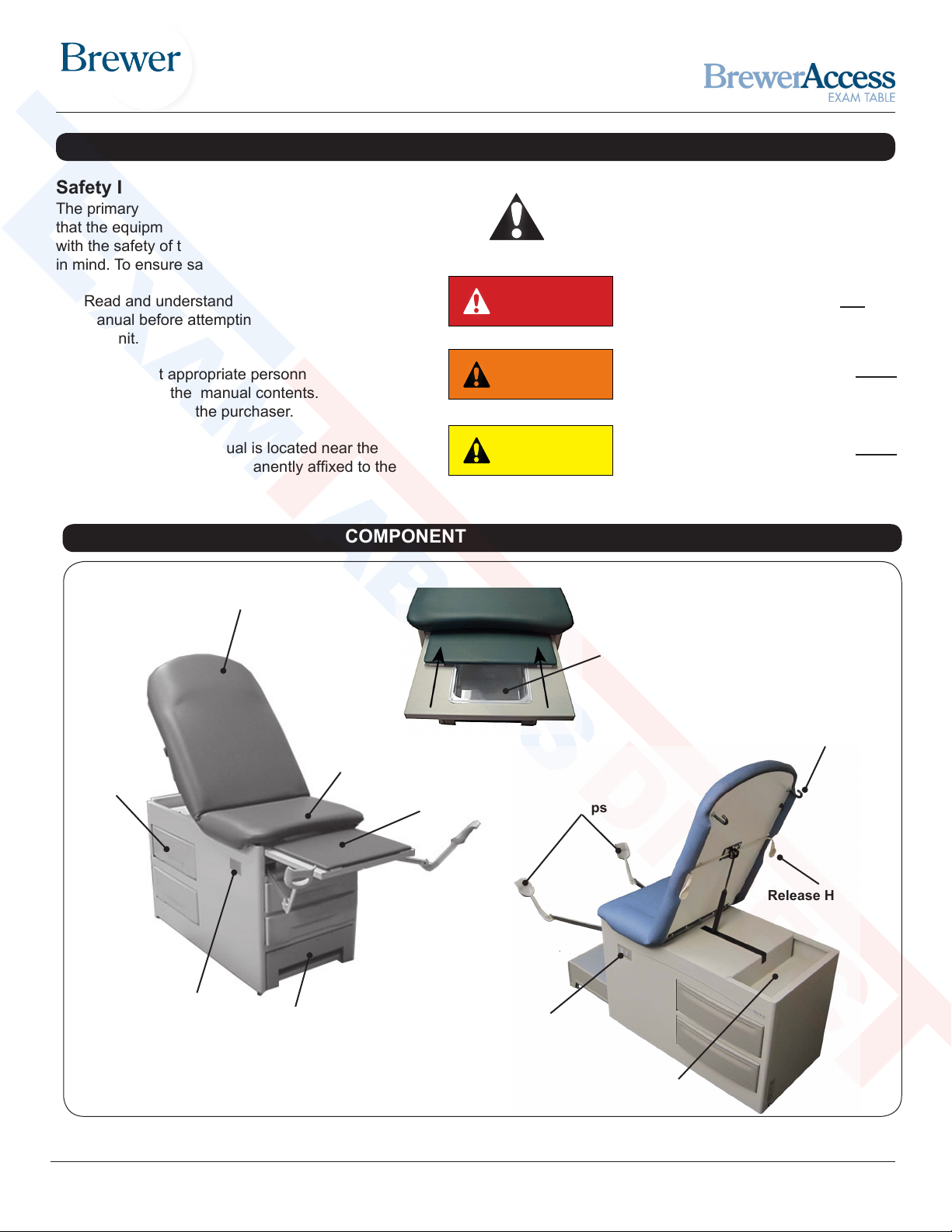
COMPONENT IDENTIFICATION
Treatment Pan
Figure 2. Component Overview
Footstep
(Extendable)
Pass-Through
Side Drawers
Back Section
Seat Section
Leg Support Pad
(Removable) Stirrups
Optional Electrical
Outlet Location
Release Handle
Paper Roll
Rod Holder
DANGER Indicates a hazardous
situation that, if not avoided, will
result in death or serious injury.
WARNING indicates a hazardous
situation which, if not avoided, could
result in death or serious injury.
CAUTION indicates a hazardous
situation which, if not avoided, could
result in minor or moderate injury.
DANGER
WARNING
CAUTION
This is the safety alert symbol. It is used to
alert you to potential physical injury hazards.
Obey all safety messages that follow this
symbol to avoid possible injury or death.
Paper Storage
Electrical Outlet
(Model 5001)
Shop tables & accessories at
ExamTablesDirect.com

Document #100578 RevJ 4 Printed in USA © 2017
Operation
Temperature .............................................50°F to 104°F
Humidity.......................................................30% to 75%
Electrical Requirements
... .........120 VAC nominal, 60 Hz, 3 amps maximum
... .........including maximum 2 amp accessory outlet
Fuse rating ..............................3 Amp/250V P/N 102007
Power Cord ........ Extends 78 in. (Minimum) from table 3
conductor, 120VAC. With hospital grade plug
Type of protection against electrical shock..... Class 1
Type of protection
against electrical shock......................... B applied parts
Type of protection against ingress of water…….Ordinary
Can accept paper rolls of.................. 21 in. x 3.5 in. dia.
Certications*......UL60601-1;CAN-CSA C22.2 No. 601.1
Pelvic Tilt..............................................................5° Rise
Drawer Warmer .................120 VAC, 65 watts, 0.5 amps
Weight of Table ...................................................220 lbs.
• With carton and skid...........................................265 lbs.
Table Weight Capacity .......................................500 lbs.
Stirrup Extension (maximum) .............................. 16 in.
Stirrup Lateral Positions...................4 Lateral Positions
Leg Support Extension (maximum)..................... 15 in.
Dimensions
• Upholstered Top ..................28.0 in. wide x 57.3 in. long
• With Leg Support Fully Extended....................... 71.0 in.
• Seat Height ........32 in to top of upholstered seat at foot
• Step................ 7.2 in. high x 20.38 in. wide x 11 in. long
Step Capacity......................................................500 lbs.
Base............ 28.2 in. high x 23.25 in. wide x 46.0 in. long
Transportation and Storage
Temperature .............................................18°F to 176°F
Humidity......................................................-10% to 90%
Explosion/Fire Hazard
Do not use this table in an explosive or oxygen
rich atmosphere. Failure to do so may result in
serious personal injury or death.
WARNING
Shock Hazard
When performing cauterization or similar
treatment, the patient must be insulated
from the metal portions of the table by non-
conductive material. Failure to do so may
result in electrical shock.
WARNING
Certications
This product has been evaluated with respect to electrical
shock, re, and mechanical hazards only in accordance with
UL60601-1; CAN/CSA C22.2 No. 601.1
NOTICE
Electromagnetic Interference (EMI)
This product is designed and built to minimize electromagnetic
interference with other devices; however, if interference is
noticed between another device and this product, remove the
interfering device from the room or plug this product into an
isolated circuit.
NOTICE
*Classied in the United States and Canada per
the standards listed above.
SPECIFICATIONS
Shop tables & accessories at
ExamTablesDirect.com

Document #100578 RevJ 5 Printed in USA © 2017
*Classied in the United States and Canada per
the standards listed above.
NOTICE
Inspect Carton and Contents
Inspect all boxes and contents for
damage. Report any damage to the
carrier immediately.
No Sharp Tools
To avoid damaging the table’s
upholstery or painted surfaces, DO
NOT use a knife or other sharp object
to open the packaging.
NOTICE
Overview
Perform the following sequence in order when setting up
the table:
- Uncrating the Table
- Leveling the Table
- Installing the Paper Rod
Tools Required
- 1/2” socket wrench
- Pliers
1. Carefully remove outer carton by removing the staples along the bottom of the carton and lift off table.
2. Unbolt the table from the shipping pallet by removing the 4 bolt screws from the pallet with a 1/2” socket wrench
and remove the shipping bracket. See Figure 3.
Uncrating
Figure 3. Table Lift Points
Lift Points
Lift Point
(Push top rear drawer through to one
side, and use opening as a hand hold)
Bolt Screw Shipping Bracket
INSTALLATION
Optimum Table Performance
For optimum table performance, allow the table to reach room
temperature before operating.
NOTICE
Shop tables & accessories at
ExamTablesDirect.com

Document #100578 RevJ 6 Printed in USA © 2017
3. Remove the table from the shipping pallet lifting at the correct lift points indicated in Figure 3. The leg support
may be used for lifting.
4. Position the table in the desired room location.
5. Remove plastic surrounding table. DO NOT use a knife or any sharp object that could damage the upholstery.
Table weighs approximately 315 lbs.
NOTICE
AVOID HANDLING DAMAGE
• To avoid damaging the table lift only at points indicated
in Figure 3.
• Do Not use stirrup or stirrup beams for lifting table.
NOTICE
Leveling the Table
A leveling screw pad is located at each corner under the table’s base (see Figure 4). Adjust the four leveling pads, by turning
them up or down, using Method 1 or Method 2 to achieve a solid, level installation. Test step by pulling out. If step drags on
oor or is difcult to pull out, adjust the front table levelers (not the step levelers) out 1 turn at a time until step pulls out easily.
Method 1 - Raise corner of table using a pry bar on a wooden block. Insert another wooden block under corner. Adjust
leveler, and remove corner block.
Method 2 - One or two people raise the front end of the table by pulled out leg support. Rear of table can be raised by
pushing the top rear pass-through drawer to one side and using the drawer opening as a hand hold.
Figure 4. Leveling Screw Pad (located under table)
INSTALLATION (CONTINUED)
Leveling Screw Pad Adjusting Leveler Method 1
Pry Bar
Wooden
Block
Wooden
Block
Adjusting Leveler Method 2
Shop tables & accessories at
ExamTablesDirect.com

Document #100578 RevJ 7 Printed in USA © 2017
Dowel Rod
Paper Roll Bracket
Paper Roll
Figure 5. Paper Roll Installation
Installing the Paper Rod
A dowel rod for supporting a paper roll is shipped with each table.
1. Slide the dowel rod through the paper roll (see Figure 5).
2. Place one end of the dowel rod on one of the paper roll
brackets, located on the rear side of the table’s back section.
3. Slide the unattached side of the dowel rod over the top of the
other paper roll bracket.
4. Ensure a secure t before using paper roll dispenser.
Conrm Voltage and Plug Type
See Specications Page for electrical rating of this unit.
The three-pronged grounding plug on the table power cord
must be plugged into a matching three-pronged, grounded,
non-isolated, correctly polarized 115 VAC receptacle.
NOTICE
INSTALLATION (CONTINUED)
Plug Table into Wall Receptacle
(Model 5001 Only)
1. Plug the male end of the power cord into a 115 volt
grounded receptacle.
WARNING
Shock Hazard
After installing or moving table, make sure
there are no damaged or exposed wires
that could result in electrical shock.
Note: Additional paper role storage is located
beneath the backrest at the rear of the table.
See Figure 2.
Shop tables & accessories at
ExamTablesDirect.com
Document #100578 RevJ 8 Printed in USA © 2017
OPERATION
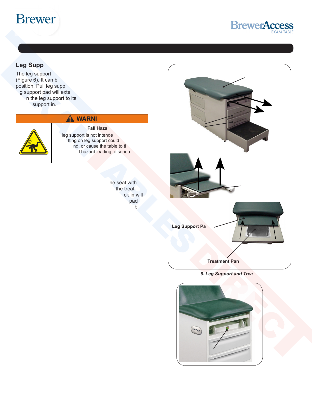
Figure 6. Leg Support and Treatment Pan
Horizontal Positioning
Leg Support Pad
Treatment Pan
Leg Support
Leg Support
The leg support is located under the seat cushion
(Figure 6). It can be extended 15” for the patient prone
position. Pull leg support out to the desired position. The
leg support pad will extend along with the leg support. To
return the leg support to its stored position simply push
the leg support in.
Leg Support Pad
The leg support pad can be slid beneath the seat with
the leg support extended for easy access to the treat-
ment pan (Figure 6). Pushing the leg support back in will
allow the glides on the pad to drop into slots. The pad
will once again come out with the leg support the next
time it is pulled out.
Treatment Pan
A removable treatment pan is built-in underneath the
leg support pad for use during examinations (Figure 6).
Pull the leg support fully out and remove the leg support
pad or slide it back under the seat to access the pan.
Remove the treatment pan for cleaning.
Fall Hazard
The leg support is not intended for use as a
seat. Sitting on leg support could cause it to
retract, bend, or cause the table to tip forward,
creating a fall hazard leading to serious injury.
WARNING
Front Drawers
Storage drawers for supplies are located at the front
of the table (Figure 6). Model 5001 is equipped with
a drawer warmer located above the top drawer that
is turned on by a switch located above the drawer
(Figure 7).
Front Drawers
Figure 7. Heater On/Off Switch
Heater Switch
Shop tables & accessories at
ExamTablesDirect.com
Document #100578 RevJ 9 Printed in USA © 2017
Figure 6. Leg Support and Treatment Pan
Horizontal Positioning
Leg Support
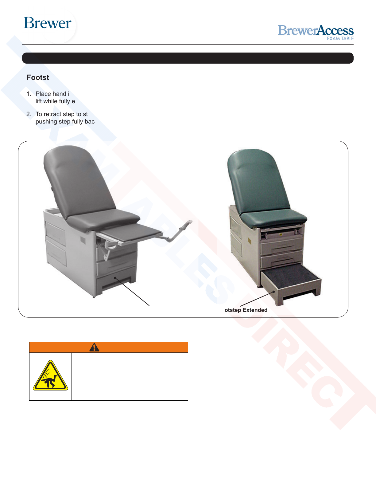
Footstep
Figure 8. Operation of Footstep
1. Place hand into opening in front of step and gently
lift while fully extending footstep (Figure 8).
2. To retract step to stowed position, gently lift while
pushing step fully back into cabinet.
Footstep Extended
Footstep Retracted
Fall Hazard
Fully extend footstep to provide ample area
for the patient to stand on. Failure to fully
extend footstep could result in a fall causing
serious injury.
WARNING
OPERATION (CONTINUED)
Shop tables & accessories at
ExamTablesDirect.com

Document #100578 RevJ 10 Printed in USA © 2017
OPERATION (CONTINUED)
Figure 9. Stirrups
Figure 11. Afx No Attachments!
Storing the Stirrups
1. To store the stirrups in the table, grasp end of
stirrup and pull straight out to its full extension.
2. Fold stirrup down against bar, then rotate it to
the inner most lateral position and slide it back
into the stowed position.
Adjustable Stirrups
Operating the Stirrups
1. To operate the stirrups, grasp end of stirrup and pull
straight out of the table (Figure 9). Lift up slightly
while sliding the stirrup out.
NOTE: Applying downward pressure when pulling stirrup
from table may make it difcult to move. Resistance
is normal and is part of the stirrup friction locking
mechanism.
2. Unfold stirrup upward to the fully open position.
3. Adjust the stirrup to the desired length by sliding it in
or out.
Stirrup Lateral Adjustment
1. Lift end of stirrup slightly and then rotate outward to
desired position.
2. When the desired position is achieved, lower the
stirrup to engage the lateral locking mechanism
(Figures 9 and 10).
3. Check that lateral locking mechanism is engaged
by attempting to move stirrup assembly side-to-side
without lifting on the stirrup end.
Figure 10. Stirrup Locking Mechanism
Close Up of Locking Mechanism
See enlargement
(Figure 9)
Use Stirrup Only as Designed
Do not use any part of the stirrup for attachment of any
device (Figure 11). Warranty will be voided.
NOTICE
Shop tables & accessories at
ExamTablesDirect.com

Document #100578 RevJ 11 Printed in USA © 2017
TABLE ADJUSTMENTS
Patient Positioning
The table is designed to accommodate the following
examination positions (Figure 12):
• Full Flat Table Position
• Chair Position
• Lithotomy (Pelvic) Position
Figure 12. Patient Positioning
Lithotomy (Pelvic) PositionFull Flat Table Position
Chair Position
Shop tables & accessories at
ExamTablesDirect.com

Document #100578 RevJ 12 Printed in USA © 2017
Back Section
1. Press and hold the release handle, lift back section upward to raise (Figure 13). Releasing the handle will
automatically lock the table in the desired position.
2. While actuating the release handle upwards, push down on the back section to lower it.
Figure 13. Operation of Upholstered Back Section
Release Handle
Back Section
Backrest Lowering Hazard
Depressing the manual backrest release
handle while a patient is seated on the
table can cause the backrest to lower
rapidly. Lower the backrest in increments
by depressing and releasing the handle.
Allowing the backrest to lower in a single
motion could cause injury to the patient.
CAUTION
TABLE ADJUSTMENTS (CONTINUED)
Shop tables & accessories at
ExamTablesDirect.com

Document #100578 RevJ 13 Printed in USA © 2017
Seat Section
Pelvic Tilt
Pelvic Tilt Bar
Figure 14. Pelvic Tilt Support Bar
Pelvic Tilt
(Model 5001 Only)
The pelvic tilt feature sets the seat angle at 0° (horizontal) or 5° (up) position.
Raising the seat section to the Pelvic Tilt Position:
1. Raise the front edge of the seat section (Figure 14).Rotate the pelvic tilt support bar upward to
its full upright position.
2. Lower the seat section onto the pelvic tilt support bar.
Lowering the seat section back to the Normal Position:
1. Slightly raise the front edge of the seat section.
2. Rotate the pelvic tilt support bar downward and lower the seat section into its prone position.
Lowering the Pelvic Tilt Mechanism
Patient must be removed from table prior to lowering
the pelvic tilt mechanism.
NOTICE
TABLE ADJUSTMENTS (CONTINUED)
Shop tables & accessories at
ExamTablesDirect.com
Document #100578 RevJ 14 Printed in USA © 2017
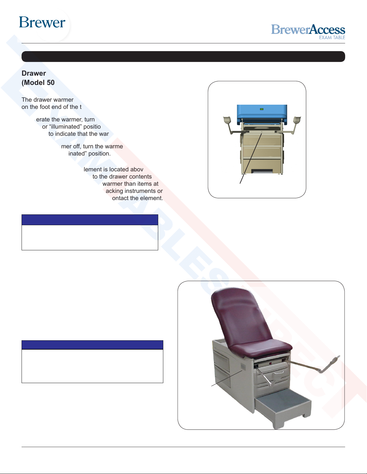
Drawer Warmer
On/Off Switch
Drawer Warmer
(Model 5001 Only)
The drawer warmer warms the contents of the top drawer
on the foot end of the table.
To operate the warmer, turn the warmer power switch to
the ON or “illuminated” position (Figure 15). The switch will
illuminate to indicate that the warmer is operating.
To turn the warmer off, turn the warmer power switch to the
OFF or “non-illuminated” position.
Figure 15. Drawer Warmer Switch
Proper Loading of the Front Drawer
Do not stack instruments in the front drawer. Place
instruments in one layer in the bottom of the drawer.
NOTICE
NOTE: The warmer element is located above the drawer
and applies radiant heat to the drawer contents. Items
closer to the element will be warmer than items at the
bottom of the drawer. Avoid stacking instruments or
allowing instruments to tip and contact the element.
Maximum Outlet Rating
Plugging a device into the outlet on the side of the table
with rating higher than 2 amps may cause the fuse at the
back of the table to blow.
NOTICE
Figure 16. Table Outlet
Electrical Outlet
(Model 5001 Only)
Model 5001 is equipped with an electrical outlet
located on the right hand side of the table (Figure 16).
The maximum total load that can be plugged into the
outlet is 2 amps.
Outlet
(Model 5001)
TABLE ADJUSTMENTS (CONTINUED)
Shop tables & accessories at
ExamTablesDirect.com

Document #100578 RevJ 15 Printed in USA © 2017
Preventative Maintenance
• Inspect table every 6 months.
• Periodically inspect the electrical cord to ensure it is
free of cuts or damage.
• Inspect the mechanical functions to ensure
satisfactory operation.
• Check fasteners to make sure they are present and
tightened securely.
• Lubricate moving parts (such as back hinge) with a
food grade silicon lubricant. Cover surrounding area to
protect from overspray. Wipe away excess lubricant.
For the latest in Cleaning Guidelines visit:
www.brewercompany.com
Table Care
Wipe Spills Immediately!
The upholstery material is resistant to most medicinal
type stains, but may be damaged by solvents and dyes.
Remove any spilled uids from the upholstery immediately.
NOTICE
Loose Fasteners and Damaged Components
Failure to perform periodic inspections of the table could
result in equipment damage.
NOTICE
Table Malfunction
If table malfunctions, immediately remove your foot from the
controls, unplug the power cord from the receptacle, and assist
the patient from the table. Service the table prior to use.
NOTICE
MAINTENANCE
ACCESSORIES
Listed below are the accessories which are authorized for use with this table.
Description Order No. Use/Restrictions
Front Drawer Organizer 100407 Intended Use - Optional front drawer dividers for sepa-
ration and organization.
Urology Tray w/Hose & Bucket 100253 Intended Use - Conveniently and safely disposes of and
captures uids during urology procedures.
Stainless Steel Treatment Pan 98464 Intended Use - Optional stainless steel treatment pan
for replacement of standard plastic treatment pan.
Welch Allyn IV Light Bracket
(customer installed)
102023 Intended Use - For mounting of Welch Allyn IV light
ACCESSORIES
Shop tables & accessories at
ExamTablesDirect.com

Document #100578 RevJ 16 Printed in USA © 2017
SERVICE
Fuse Replacement (Model 5001 Only)
1. Unplug table from wall receptacle.
2. Push bottom rear drawer to the left to access fuse assembly (Figure 17).
3. Push the fuse holder cap in with a at screwdriver (Figure 18).
4. Rotate 1/4 turn counterclockwise to remove cap and fuse (Figure 19).
5. Replace fuse with Brewer 102007, 3A 250V fuse.
6. Push fuse into cap.
7. Push cap with fuse into fuse holder and rotate 1/4 turn clockwise to install.
8. Plug table into wall receptacle.
9. Check drawer warmer and outlet for proper function.
Figure 18. Fuse Holder CapFigure 17. Bottom Drawer Moved to
Show Fuse Location
Fuse
CLEANING
WARNING
Shock Hazard
Disconnect power by removing plug from
wall receptacle before servicing table.
WARRANTY
For Brewer Warranty Information:
Visit www.brewercompany.com or contact the Brewer Customer Service Department at (1-888-Brewer1).
Figure 19. Fuse Removal
Shop tables & accessories at
ExamTablesDirect.com
Other manuals for Access 5000
2
This manual suits for next models
1
Table of contents
Other brewer Medical Equipment manuals


Popular Medical Equipment manuals by other brands

Datex-Ohmeda
Datex-Ohmeda S/5 M-COPSv Technical Reference Manual Slot

HYPERICE
HYPERICE Normatec 3 Let's get started

Datex-Ohmeda
Datex-Ohmeda S/5 Compact Anesthesia Monitor Technical reference manual

Arthrex
Arthrex Synergy Resection quick start guide

EMERGENT
EMERGENT Porto2vent CPAP os Operator's manual

Sirona
Sirona ORTHOPHOS XG 5 operating instructions


