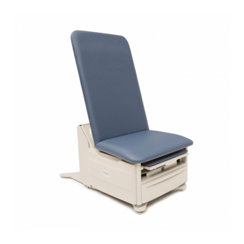
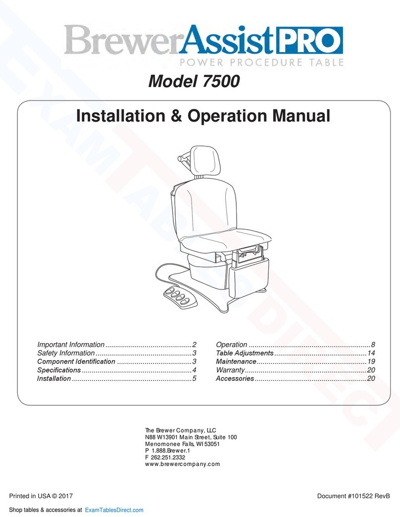
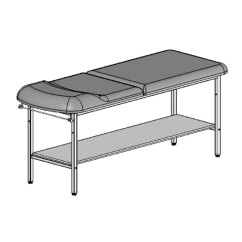
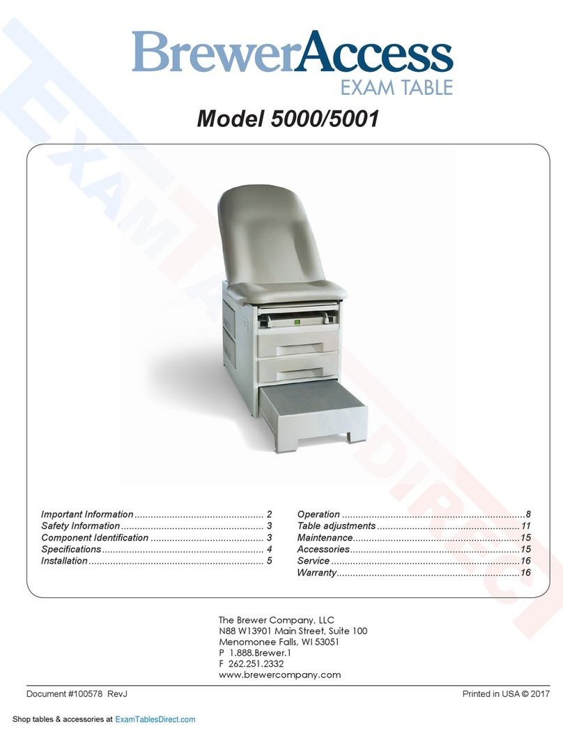
brewer ASSIST 7000 User manual

Document # 99300 RevB Printed in USA © 2017
Installation & Operation Manual
Important Information............................................2
Safety Information.................................................3
Component Identication ......................................3
Specications ........................................................4
Installation .............................................................5
Operation ..............................................................8
Table Adjustments...............................................12
Maintenance........................................................15
Warranty..............................................................15
Accessories..........................................................16
The Brewer Company, LLC
N88 W13901 Main Street, Suite 100
Menomonee Falls, WI 53051
P 1.888.Brewer.1
F 262.251.2332
www.brewercompany.com
Model 7000
Shop tables & accessories at
ExamTablesDirect.com

Document # 99300 RevB 2 Printed in USA © 2017
Service
If you require assistance with the installation or operation
of your Brewer Model 7000 table, call the Brewer
Customer Service Department at (1-888-Brewer1). Our
trained staff will attempt to assist you in correcting the
problem directly over the phone. If service is required, a
factory authorized technician will be sent to your location.
Please ll in the following information for use when calling
the Brewer Company or your distributor with questions
regarding your unit. See Figure 1 for model and serial
number location.
Date of Purchase _________________________
Serial Number ____________________________
Model Number ___________________________
Authorized
Dealer Name ____________________________
Dealer
Phone Number ___________________________
Dealer Address ___________________________
IMPORTANT INFORMATION
General
Read and understand all operating instructions, safety
information, and maintenance requirements contained
in this manual prior to operating the table. Become
familiar with all of the table functions before using it with
a patient.
The Brewer ASSIST Powered Procedure Table is
designed to provide positioning and support of patients
during general examinations conducted by qualied
medical professionals.
The ASSIST table is primarily used in examination
rooms for general examinations and minor procedures.
The wide variety of positions provided by four powered
motions, adjustable legrest, adjustable headrest, stirrups
and treatment pan, create a safe and convenient patient
positioning table for most examinations and procedures
performed in the doctor’s ofce.
The table is easily adjusted to a wide variety of positions
using the convenient foot control provided with the
table. An optional hand pendant may be purchased
which can be used in conjunction with the foot control.
The table height can be adjusted from 19” to 40”. The
table seating surface can be moved from the normal
horizontal position to an angle of 30°. The backrest can
be adjusted from a at lying down position, to an 85°
angle for seating. The legrest can be adjusted from a
vertical position for seating, to a horizontal position for
laying.
In addition to the electronically controlled positions noted
above, several manual adjustments are available:
1. The legrest can be manually adjusted from a sitting
to a kneeling position.
2. With the table in the horizontal position, the legrest
can be extended an additional 5” of travel for tall
patients.
3. Stirrups may be manually extended and positioned
innitely within the lateral range of travel.
4. A removable treatment pan is stowed beneath the
front of the seat and can be pulled out for use during
examinations.
5. The headrest is multi-adjustable using three clamp
action locking levers.
6. The backrest incorporates a self-storing paper roll.
Figure 1. Model and Serial Number Location
Model &
Serial Number
Shop tables & accessories at
ExamTablesDirect.com

Document # 99300 RevB 3 Printed in USA © 2017
Safety Information
The primary concern of The Brewer Company is that
the equipment is operated and maintained with the
safety of the patient and healthcare staff in mind. To
ensure safe and reliable operation:
•Read and understand all instructions in this
manual before attempting to install or operate
the unit.
•Ensure that appropriate personnel are
informed on the manual contents. This is the
responsibility of the purchaser.
•Ensure that this manual is located near the
table, or if possible permanently afxed to the
table.
SAFETY INFORMATION
COMPONENT IDENTIFICATION
Leg Section
Headrest
Backrest
Stirrups
Seat
Treatment
Pan
Headrest Linkage
Assembly
Foot Control
Figure 2. Component Overview
DANGER Indicates a hazardous
situation that, if not avoided, will
result in death or serious injury.
WARNING indicates a hazardous
situation which, if not avoided, could
result in death or serious injury.
CAUTION indicates a hazardous
situation which, if not avoided, could
result in minor or moderate injury.
DANGER
WARNING
CAUTION
This is the safety alert symbol. It is used to
alert you to potential physical injury hazards.
Obey all safety messages that follow this
symbol to avoid possible injury or death.
Shop tables & accessories at
ExamTablesDirect.com

Document # 99300 RevB 4 Printed in USA © 2017
SPECIFICATIONS
Power Cord
• Length.....................................Extends 70 in. from Table
• Type ..............................................................Detachable
• Conductors..................................18 AWG / 3 Conductor
• Grade ...............................................Hospital Grade Plug
Type of protection against electrical shock
• Model 7000 .............................Class 2 Double Insulated
• Patient applied parts ............................................Type B
Type of protection against ingress of water….Ordinary
Paper Roll Sizes
• Regular......................................................18 in. x 3.5 in.
• Long..........................................................21 in. x 3.5 in.
Certications*..UL60601-1; CAN-CSA C22.2 No. 601.1
Operating Conditions
Temperature Range ....................................65° to 85°F
Humidity Range..........................................10% to 90%
Transportation and Storage
• Temperature Range.....................................-20°F to 85°F
• Humidity Range..............................................10% to 90%
*Classied in the United States and Canada per
the standards listed above.
Weight of Table...................................................550 lbs.
Load Rating (maximum)
• Seat/Back...........................................................450 lbs.
• Legrest (Flat & Kneeling) ...................................450 lbs.
• Headrest.............................................................100 lbs.
Back Section Range.............0° (horizontal) to +85° ± 5°
Table Top Height Range.........19 ± 0.5 in. to 40 ± 1.0 in.
Leg Section Range..........0° (horizontal) to 90° (vertical)
Table Top
Tilt Range............... 0° (horizontal) to +30° ± 5° (foot up)
Dimensions
• Upholstered Headrest...............13 in. wide x 11 in. high
• Upholstered Top..................28.0 in. wide x 44.5 in. long
• Upholstered
Leg Rest ..…………………16.5 in. wide x 11.25 in. high
• Overall Length................................................69 in. long
• With Headrest/Footrest Extended ..................90 in. long
Electrical Requirements
..................115 VAC nominal, 60 HZ, 5.8 amps maximum
Duty Cycle (10%)
................. 2 minutes on / 18 minutes off (motor run time)
WARNING
Shock Hazard
When performing cauterization or similar
treatment, the patient must be insulated
from the metal portions of the table by
non-conductive material. Failure to do
so may result in electrical shock.
WARNING
Explosion/Fire Hazard
Do not use this table in an explosive or oxy-
gen rich atmosphere. Failure to do so may
result in serious personal injury or death.
Certications
This product has been evaluated with respect to electrical
shock, re, and mechanical hazards only in accordance with
UL60601-1; CAN/CSA C22.2 No. 601.1
NOTICE
Electromagnetic Interference (EMI)
This product is designed and built to minimize electromagnetic
interference with other devices. However, if interference is
noticed between another device and this product, remove the
interfering device from the room or plug this product into an
isolated circuit.
NOTICE
Shop tables & accessories at
ExamTablesDirect.com

Document # 99300 RevB 5 Printed in USA © 2017
Overview
Perform the following sequence in order when setting up
the table:
- Uncrating
- Leveling the Base
- Installing the Foot Control
Uncrating
1. Using a 1/2” open-end wrench, or socket, unbolt the
table from the wooden shipping skid by removing the
four bolts located underneath the table’s base; two
on each side.
2. Remove the table from the shipping skid by sliding it
off the front of the skid. Be sure to lift at the correct
points as indicated in Figure 3. Position the table in
the desired room location.
3. Remove packing tape from stirrups (Figure 4). Pull
out treatment pan slide and remove packing tape
from the treatment pan assembly components.
Return treatment pan slide to its stowed position.
INSTALLATION
Figure 3. Table Lift Points
Figure 4. Stirrups and Treatment Pan
DO NOT lift at these points!
Lift table at these points
Do Not Lift
NOTICE
Inspect Carton and Contents
Inspect all boxes and contents for
damage. Report any damage to the carrier
immediately.
No Sharp Tools
To avoid damaging the table’s upholstery
or painted surfaces, DO NOT use a knife or
other sharp object to open the packaging.
NOTICE
NOTICE
The table weighs approximately 550 lbs.
Optimum Table Performance
For optimum table performance, allow the table to
reach room temperature before operating.
NOTICE
Shop tables & accessories at
ExamTablesDirect.com

Document # 99300 RevB 6 Printed in USA © 2017
Figure 5. Leveling Screw Pad (located under table)
Figure 6. Power Cord & Foot Control Cord Receptacles
Leveling the Table
A leveling screw pad (Figure 5) is located in four places
under the table’s base.Adjust the six leveling pads to
achieve a solid, level installation.
INSTALLATION (CONTINUED)
Prevent Leveler Damage
Levelers must remain in the table and be fully engaged a
minimum of (3) turns. If levelers are not fully engaged in the base,
damage to the threading in the base and/or leveler can occur.
NOTICE
Installing the Power Cord
1. Insert the female plug end of the power cord into the re-
ceptacle on the table (Figure 6).
2. Plug the power cord into a 115 Volt grounded receptacle.
Conrm Voltage and Plug Type
See Specications Page for electrical rating of this unit.
The three-pronged grounding plug on the table power
cord must be plugged into a matching three-pronged,
grounded, non-isolated, correctly polarized 115 VAC
receptacle.
NOTICE
Shop tables & accessories at
ExamTablesDirect.com

Document # 99300 RevB 7 Printed in USA © 2017
WARNING
Shock Hazard
After installing or moving table, make sure
there are no damaged or exposed wires that
could result in electrical shock.
Installing the Foot Control
1. Remove the foot control from the shipping box.
2. Insert the end of the foot control cord into the foot
control receptacle on the table (Figure 6). Make
sure the tab on the plug is aligned with the slot in the
receptacle.
Note: The plug may appear to be fully inserted and
yet have some distance to go. Wiggle the plug while
pushing it in rmly to ensure that it is fully seated
(Figure 7).
Foot Control Plug
Even with or Above
Receptacle Rim
Foot Control Plug not Fully Inserted
Foot Control Plug Fully Inserted
Foot Control Plug
Below Receptacle Rim
INSTALLATION (CONTINUED)
Figure 7. Foot Control Properly Pugged In
The foot control is moisture resistant and runs on low volt-
age. To avoid temporary or permanent damage to the foot
control, do not immerse in water or liquids.
NOTICE
Shop tables & accessories at
ExamTablesDirect.com

Document # 99300 RevB 8 Printed in USA © 2017
OPERATION
Figure 8. Foot Control
BACK UP
TILT UP
TILT DOWN LEGREST DOWN
TABLE UP
TABLE DOWN
BACK DOWN
LEGREST UP
Foot Control
The model 7000 ASSIST Powered Procedure Table
comes standard with a four pedal foot control (Figure 8).
The table adjustments include height, seat tilt, backrest
angle, and legrest angle.
Unintended Operation
To avoid accidental operation, keep foreign objects away
from controls. Be sure the controls are not positioned below
the legrest or headrest linkage.
NOTICE
Shop tables & accessories at
ExamTablesDirect.com

Document # 99300 RevB 9 Printed in USA © 2017
Treatment Pan
1. To expose the treatment pan for use, grasp the tray
handle and pull until tray is fully extended (Figure 9).
2. The pan can be easily removed for cleaning with the tray
fully extended. Fully seat pan into tray when clean.
3. Push the tray handle as far in as it will go to fully stow
the treatment pan after use. A light clicking sound will
be heard just before the pan reaches its fully stowed
position.(The light clicking sound is created by a switch
that allows the legrest to move upward).
OPERATION (CONTINUED)
Tray
Treatment
Pan
Figure 9. Treatment Pan
Headrest Positions
1. To move the headrest, rotate the three handles
to their open position. Move the headrest to its
desired location. Rotate the 3 handles to their locked
position as shown in Figure 10.
2. Each section of the headrest can be adjusted
independently by rotating the handle to the open
position, moving the desired section, and then
rotating the handle to the closed position.
NOTE: Make sure all three handles are locked. A handle
is locked correctly when it is pushed past center and
the force of the clamping action pulls the handle into the
locked position and holds it there.
Figure 10. Headrest Handles
Headrest Handle
(Locked)
Upper Handle
(Locked)
Lower Handle
(Locked)
Make sure headrest is securely locked into position before
use. Failure to have the three handles correctly locked
could result in headrest falling during a procedure which
could result in serious personal injury.
CAUTION
Shop tables & accessories at
ExamTablesDirect.com

Document # 99300 RevB 10 Printed in USA © 2017
Legrest Extension
In the horizontal position, the legrest can be extended 5”
to increase the overall length of the table (Figure 11).
Lift up on the legrest and pull outward to extend the
legrest. To return the legrest to the shortest position, lift
up on the legrest and push fully inward.
Figure 11. Legrest Extension
To prevent damage to the unit, the legrest must be returned
to the shortest position prior to lowering the legrest to the
vertical position.
NOTICE
OPERATION (CONTINUED)
Figure 12. Legrest Kneeling Position
Legrest Kneeling Position
The legrest can be rotated to a kneeling position
(Figure 12).
1. Grasp the legrest cushion on both sides.
2. Rotate the cushion upward until rotation stops.
3. Slide the legrest downward and rotate the cushion
downward to engage the stop. Two height positions
are provided.
Cam positioned in slot
Lift up over-center
1 2 3
Make Sure Legrest is Engaged with Stops
Make sure the legrest cushion is fully engaged with
the stops on both sides. When properly engaged, the
legrest cushion is parallel to the ground.
NOTICE
Shop tables & accessories at
ExamTablesDirect.com

Document # 99300 RevB 11 Printed in USA © 2017
Adjustable Stirrups
Figure 13. Operating the Stirrups
Operating the StirrupS
1. To operate the stirrups, grasp end of stirrup and pull straight
out of the table. Lift up slightly while sliding the stirrup out
(Figure 13).
NOTE: Applying downward pressure when pulling stirrup from
table may make it difcult to move. Resistance is normal and is
part of the stirrup friction locking mechanism
2. Unfold stirrup upward to the fully open position.
3. Adjust the stirrup to the desired length by sliding it in or out.
Stirrup LateraL adjuStment
1. Lift end of stirrup and then rotate outward to
desired position (Figure 14).
2. When the desired position is achieved, lower the stirrup to
engage the lateral locking mechanism.
3. Check that lateral locking mechanism is engaged by
attempting to rotate stirrup assembly without lifting on the
stirrup end.
StOring the StirrupS
1. To store the stirrups in the table, grasp end of stirrup and pull
straight out to its full extension (Figure 15).
2. Fold stirrup down against bar, then rotate it to the inner most
lateral position and slide it back into the stowed position.
Figure 14. Stirrup Lateral Adjustment
Pull Stirrup out, then unfold
Lateral
Locking
Mechanism
Figure 15. Storing the Stirrups
Figure 16. Afx No Attachments!
OPERATION (CONTINUED)
Use Stirrup Only as Designed
Do not use any part of the stirrup for attachment of any device (Figure 16).
Warranty will be voided. If knee crutches are required for use, order mounting
adapters, clamps, and rails shown in the Accessories Section.
NOTICE
Shop tables & accessories at
ExamTablesDirect.com

Document # 99300 RevB 12 Printed in USA © 2017
Figure 17. Paper Roll
Slot
Paper Roll
To change a paper roll, insert the paper through the slot
in the backrest shrouding and set the paper roll in the
holder (Figure 17).
OPERATION (CONTINUED)
WARNING
Area Not Clear Hazard
Before initiating movement keep personnel and equipment
clear of table to avoid personal injury or damage to the
equipment.
Figure 18. Table Height Positioning
Table Height Control
Table Height
The table top can be adjusted to any height between 19” to 40” (Figure 18).
1. To raise the table, depress and hold the Table Up
pedal (Figure 8) until the desired height is achieved,
then release the pedal.
2. To lower the table, depress and hold the Table Down
pedal until the desired height is achieved, then
release the pedal.
Avoid Continuous Operation
If the table is operated continuously causing the control
to exceed its allowable operating temperature, the control
will shut off. If normal operation ceases, do not attempt to
operate the table. Allow the table to cool for 10-15 minutes
before attempting to use again. The control will automatically
reset when it has reached a safe operating temperature.
NOTICE
TABLE ADJUSTMENTS
Shop tables & accessories at
ExamTablesDirect.com

Document # 99300 RevB 13 Printed in USA © 2017
TABLE ADJUSTMENTS (CONTINUED)
Tilt Function
The table top can be tilted to any angle between
horizontal and +30° (foot end of table raised)
(Figure 20).
1. To tilt the foot end of the table upward, depress and
hold the Tilt Up pedal (Figure 8) until the desired
angle is achieved, then release the pedal.
2. To tilt the foot end of the table downward, depress
and hold the Tilt Down pedal until the desired angle
is achieved, then release the pedal .
Figure 20. Tilt Function
Figure 19. Adjusting Backrest
Backrest Position Control
Figure 21. Do Not Allow Headrest to Contact Objects
Back Positions
The back can be adjusted to any angle between
horizontal and 85° (Figure 19).
1. To adjust the back from a chair (upright) position
to a horizontal position, depress and hold the Back
Down pedal (Figure 8) until the desired angle is
achieved, then release the pedal.
2. To adjust the backrest from a horizontal position to a
chair (upright) position, depress and hold the Back
Up pedal until the desired angle is achieved, then
release the pedal.
Tilt Function Control
Back Actuator-Push Only
The back is positioned by a “push only” actuator that
raises the back. When lowered, the actuator retracts
and gravity causes the back to lower.
NOTICE
Headrest Linkage Clearance
Use care when tilting the table to avoid contact between
the headrest linkage and the oor or other objects.
(Figure 21).
NOTICE
Shop tables & accessories at
ExamTablesDirect.com

Document # 99300 RevB 14 Printed in USA © 2017
Figure 22. Legrest Positions
Legrest Positions
The legrest can be adjusted from a horizontal position to
a vertical position (Figure 22).
1. To adjust the legrest from a vertical position to a
horizontal position, depress and hold the Legrest Up
pedal (Figure 8) until the desired angle is achieved,
then release the pedal.
2. To adjust the legrest from a horizontal position to
a vertical position, depress and hold the Legrest
Down pedal until the desired angle is achieved, then
release the pedal.
Legrest Position Control
TABLE ADJUSTMENTS (CONTINUED)
Legrest Actuator-Push Only
The legrest is positioned by a “push only” actuator that
raises the legrest. When lowered, the actuator retracts
and gravity causes the legrest to lower.
NOTICE
Treatment Pan Tray Must be Stowed
The legrest will not rise if the treatment pan tray is
extended. If the legrest is inoperable, check to ensure
that the treatment pan tray is in its fully stowed position.
NOTICE
Actuator Travel Limit Protection
Each control function will automatically stop moving when
either the UP or DOWN travel limit is reached. If the foot pedal
is pressed with travel at its limit, the actuator will not operate.
Sensors prevent the actuator motor from operating when travel
limit has been reached, preventing wear of the actuator.
NOTICE
Shop tables & accessories at
ExamTablesDirect.com

Document # 99300 RevB 15 Printed in USA © 2017
MAINTENANCE
Table Care
Wipe Spills Immediately!
The upholstery material is resistant to most medicinal
type stains, but may be damaged by solvents and
dyes. Remove any spilled uids from the upholstery
immediately.
NOTICE
WARNING
Shock Hazard
Disconnect power by removing plug from
wall receptacle before servicing table.
Table Malfunction
If table malfunctions, immediately remove your foot from the
controls, unplug the power cord from the receptacle, and
assist the patient from the table. Service the table prior to
use.
NOTICE
Preventative Maintenance
• Inspect table every 6 months.
• Periodically inspect the electrical and foot control
cords to ensure they are free of cuts or damage.
• Inspect the mechanical functions to ensure satisfac-
tory operation.
• Check fasteners to make sure they are present and
tightened securely.
• Lubricate the backrest hinge with a food grade
silicon lubricant. Cover surrounding area with cloth
to protect from overspray and wipe excess.
Loose Fasteners and Damaged Components
Failure to perform periodic inspections of the
table could result in equipment damage.
NOTICE
For the latest in Cleaning Guidelines visit:
www.brewercompany.com
WARRANTY
For Brewer Warranty Information:
Visit www.brewercompany.com or contact the Brewer Customer Service Department at (1-888-Brewer1).
Shop tables & accessories at
ExamTablesDirect.com

Document # 99300 RevB 16 Printed in USA © 2017
ACCESSORIES
Listed below are the accessories which are authorized for use with this table.
Description Order No. Use/Restrictions
Urology Tray w/Hose & Bucket 100253 Conveniently and safely captures uids during urology
procedures.
Side Rails (qty 2) 99501 Used to attach accessories. Can be mounted to seat or
back.
Universal Socket Clamp (qty 1) 99502 Used to mount deluxe articulating knee crutches to ac-
cessory rail.
Welch Allyn IV Light Bracket
(customer installed) 102025 For mounting of Welch Allyn IV light.
Grab Bars (qty 2) 99497 Requires 99501 Side Rails for mounting to seat.
Articulating Arm Board 99499 Requires 99501 Side Rails for mounting to backrest.
Hand Pendant 99500 Can be used independantly or in conjunction with foot
control. Table is pre-wired to accept hand pendant.
Deluxe Articulating Knee Crutches 99504 Allows leg positioning for ease of examination.
Contains one LH and one RH Knee Crutch.
Side Rails (qty 2)
99501 Provides attachment point for Knee Crutch Clamps.
Universal Socket Clamp (qty 1)
99502 Clamps Knee Crutch to Side Rail.
Must order (2) two 99502 Universal Socket Clamps.
The following items are required for the Articulating Knee Crutch accessory:
Shop tables & accessories at
ExamTablesDirect.com
Other manuals for ASSIST 7000
1
Table of contents
Other brewer Medical Equipment manuals
Popular Medical Equipment manuals by other brands

Getinge
Getinge Arjohuntleigh Nimbus 3 Professional Instructions for use

Mettler Electronics
Mettler Electronics Sonicator 730 Maintenance manual

Pressalit Care
Pressalit Care R1100 Mounting instruction

Denas MS
Denas MS DENAS-T operating manual

bort medical
bort medical ActiveColor quick guide

AccuVein
AccuVein AV400 user manual

