3
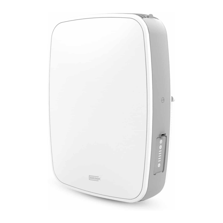
ABrink HRV . . . . . . . . . . . . . . . . . . .
Brink HRV . . . . . . . . . . . . . . . . . . . .
Brink WRG . . . . . . . . . . . . . . . . . . .
Brink CWL . . . . . . . . . . . . . . . . . . . .
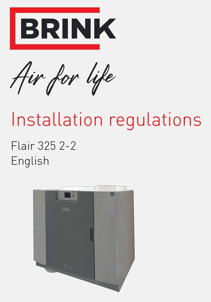
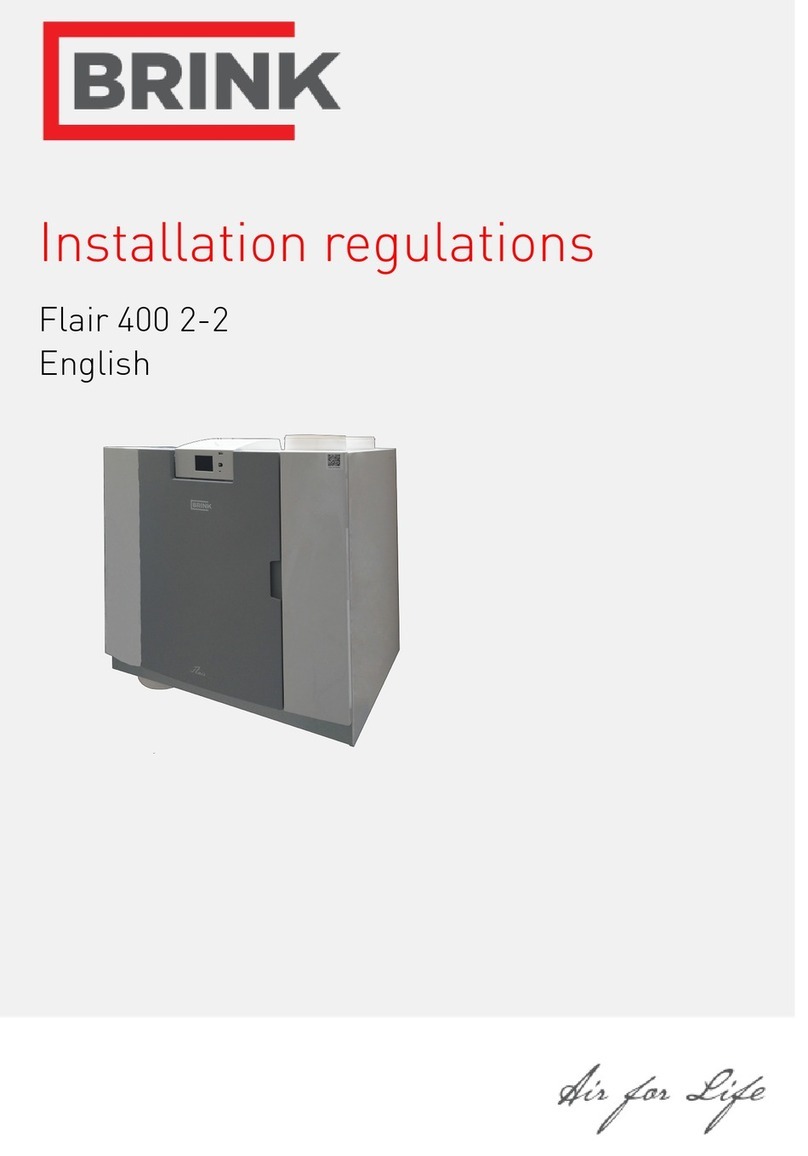
Jednotka rekuperace tepla Brink
Brink heat recovery unit
Brink Wärmerückgewinnungseinheit
Brink unité de récupération de chaleur
BPřívodní sběrné vzduchové potrubí .
Supply manifold . . . . . . . . . . . . . . . .
Frischluftverteiler . . . . . . . . . . . . . . .
Répartiteur d'air d'amenée . . . . . . . .
Sběrné vzduchové potrubí, ke kterému jsou připojeny veškeré trubice přívodu vzduchu, viz odst. 1.3.1
Manifold to which all supply air ducts are connected; see § 1.3.1
Verteilerschrank, an den sämtliche Zuluftkanäle gekoppelt werden; siehe § 1.3.1
COdsávací sběrné vzduchové potrubí
Abluftverteiler . . . . . . . . . . . . . . . . . .
Répartiteur d'air d'évacuation . . . . . .
Sběrné vzduchové potrubí, ke kterému jsou připojeny veškeré trubice odsávání vzduchu, viz odst. 1.3.2
Verteilerschrank, an den sämtliche Abluftkanäle gekoppelt werden; siehe § 1.3.1
DSyntetické vzduchové trubice HR. . .
HR synthetic air ducts . . . . . . . . . . . .
Wärmegedämmtes Rohrsystem . . . .
aus Kunststoff
Conduites d'air HR en matière . . . . .
The synthetic HR ducts are used to connect the roof and wall sleeves as well as the manifolds to
the HRV. Use of these synthetic ducts prevents condensation
Das Wärmegedämmte Rohrsystem aus Kunststof wird verwendet, um die Dach- bzw. Fassaden-
durchführung und die Luftverteiler an den WRV Gerät anzuschließen. Der Einsatz dieser Kunst-
stoffrohre verhindert die Bildung von Kondensat.
E
Odsávací ventilační průchodka střechou
roof
Abluft-Lüftungsdurchführung durchs.
Dach
Passage de ventilation Évacuation . .
par la toiture
-
lation instructions supplied with the HRV.
Der Lüftungsluftabzug durchs Dach; für Einbau und/oder Abmessungen siehe die zum WRG Gerät
mitgelieferte Installationsanleitung.
L'évacuation de l'air de ventilation par la toiture ; pour la mise en place et / ou les dimensions voir
les Consignes d'installations livrées avec le CWL.
FPřívodní ventilační průchodka střechou
-
rior wall
Frischluftzufuhr durch die Fassade. .
Amenée de ventilation d'air par . . . .
la façade
The internally insulated wall sleeve through which the clean outdoor air is sucked in; installation
and dimensions are described in the installation instructions supplied with the HRV.
Die innenseitig gedämmte Fassadendurchführung, durch die saubere Außenluft angesaugt wird;
für den Einbau und/oder Abmessungen siehe die zum WRG mitgelieferte Installationsanleitung.
L'évacuation de l'air de ventilation par la toiture ; pour la mise en place et / ou les dimensions voir
les Consignes d'installations livrées avec le CWL.
GSyntetické potrubí pro rozvod vzduchu
Synthetic air distribution duct . . . . . .
Flachkanal . . . . . . . . . . . . . . . . . . . .
HHrdla sběrného vzduchového potrubí
Manifold couplers . . . . . . . . . . . . . . .
Verteilerschrankstutzen . . . . . . . . . .
Branchement de boîtier de . . . . . . . .
répartition
The manifold couplers are used to connect the air ducts to the manifold; there are manifolds with
5, 10 or 15 couplers; see § 1.3.2
Der Verteilerschrankstutzen wird für den Anschluss der Luftkanäle an den Luftverteilerschrank
verwendet; es gibt einen Verteilerschrank mit 5, 10 oder 15 Verteilerschrankstutzen; siehe § 1.3.2
Le branchement de boîtier de répartition est utilisé pour raccorder les conduites d'air au boîtier de
répartition d'air ; le boîtier de répartition d'air peut avoir 5, 10 ou 15 branchements de boîtier de
répartition d'air; voir le § 1.3.2
I
Regulátor proudění vzduchu
Flow rate regulator . . . . . . . . . . . . . .
Drosselscheibe . . . . . . . . . . . . . . . . .
. . . . . . . . . . . . . .
Flow rate regulators are mounted in the manifold couplers on the air distribution duct sealing ring;
; see § 1.3.4.
Die Drosselscheibe wird in die Verteilerschrankstutzen am montierten Dichtring des Luftvertei-
lerschlauchs eingebaut; durch Wegschneiden eines Ringes bzw. mehrerer Ringe lässt sich der
Luftdurchsatz damit anpassen; siehe § 1.3.4
d'adapter l'ouverture d'air; voir le § 1.3.4.
Syntetické trubice HR se používají k připojení střešních a stěnových průchodek i sběrných vzducho-
vých potrubí k jednotce rekuperace tepla. Používání těchto syntetických trubic zabraňuje kondenzaci.
Odsávání vzduchu střechou; instalace a rozměry jsou popsány v pokynech pro instalaci dodávaných s
jednotkou rekuperace tepla.
Stěnová průchodka s vnitřní izolací, kterou se nasává čistý venkovní vzduch; instalace a rozměry jsou
popsány v pokynech pro instalaci dodávaných s jednotkou rekuperace tepla
Syntetické potrubí pro rozvod vzduchu o rozměrech 50 x 100 mm; viz 1.3.5.
Hrdla sběrného vzduchového potrubí se používají pro připojení vzduchových trubic ke sběrnému
vzduchovému potrubí; tato potrubí mají 5, 10 nebo 15 spojek – viz 1.3.2.
Regulátory rychlosti proudění vzduchu se montují do spojek sběrného vzduchového potrubí na těsnící
kroužek potrubí pro rozvod vzduchu; průchod vzduchu lze upravit odříznutím jednoho nebo více
kroužků – viz 1.3.4.
Systému pro rozvod vzduchu/ Air Distribution System/ Luftverteilersystems/ Systéme de répartition d‘air
1retpahC/Kapitola 1noisreV/Versa
1ertipahC/1letipaKelédoM/gnurhüfsuA
