Broan 192 User manual

1
IMPORTANT SAFETY INSTRUCTIONS
WARNING – TO REDUCE THE RISK OF FIRE, ELECTRIC
SHOCK, OR INJURY TO PERSONS, OBSERVE THE FOLLOW-
ING:
1. All electrical work must be done in accordance with local or
nationalelectricalcodeasapplicable.For safety, this product
must be grounded. Ifyouareunfamiliarwithmethodsofin-
stallingelectricalwiring,securetheservices ofaqualifiedelec-
trician.
2. Whenwiring, servicing orcleaningthisunit,turnoffpowerand
lockout servicepanel. Failureto doso couldallow othersor
thermostatto turn on power unexpectedly which may cause
fatalelectricalshock.
3. Toavoid electricalshock:
•Do not installunitinatuborshowerenclosureoranyloca-
tionwhereitmaycomeincontact with water.
•Never placeaswitchwhere it can be reachedfromatub or
shower.
4. Do not installthisunit in an areawhere chemicals and other
flammablesarestoredorused.Explosionandfiremayresult.
CAUTION
1. ThisproductmayONLYbeinstalledinawall.Do not mountin
anyotherposition.
2. Install heater at least 12" from floor or any adjacent vertical
surface.
3. Do not locate heater behind a door, furniture, drapes, etc.,
wheretheairflowto the unit wouldberestricted.
4. Provideheater with anappropriately-ratedelectricalcircuitto
preventtrippedbreakersor blown fuses.
5. Do not connectheatertodimmerswitchorspeedcontrol.
6. Toavoid motor bearing damage and noisyand/orunbalanced
impellers,keepdrywallspray,constructiondust,etc.,offpower
unit.
7. Pleaseread specification label on productforfurtherinforma-
tionandrequirement.
INSTALLATION INSTRUCTIONS
READ & SAVE THESE INSTRUCTIONS!
Wall Heater
MODELS: 192, 194, 198
FIGURE 1
PLAN THE INSTALLATION
This heater is intended to be used to supply supplemental heat
fromawalllocationinneworexistingconstruction.
Choosea location where edge of heater will be at least 12" from
thefloororanyadjacentverticalsurface.
The heater can be operated using its built-in thermostat or a re-
motethermostat(Choose eithertheModel86WLine-Voltagether-
mostatorusetheModel82Transfomer/Relaywithanappropriate
low-voltagethermostat.).The Model85Kitisavailableforsurface-
mountapplications.Purchasetheseaccessories separately.
Plantosupplytheheater with proper line voltage andappropriate
powercable.
NOTE: Powercan be tappedfroma nearby circuitdepending on
theheaterwattagerequired and theamperageratingofthecircuit.
Heatercanbe convertedtohalf-wattagetoavoidoverloadingsuch
circuits.
MODEL VOLTS AMPS WATTS BTU/HR
192 240 8.33/4.17 2000/1000 6827/3413
194 240 12.50/6.25 3000/1500 10240/5120
198 240 16.67/8.33 4000/2000 13653/6827
DRYWALL
THERMAL
OVERLOAD
GRILLE
BUILT-IN
THERMOSTAT
HEATER HOUSING
POWER CABLE
Bold ratingsare factorywired.
See“OPTIONAL WIRINGCONVERSIONS” sectionfor wattage
conversioninstructions.
Refer to FIGURE 1
Followthesebasicstepswheninstallingthisheater:
1) Nailhousing to studs.
2) Connectpowercable.
3) Fastenheater assembly andgrilletohousing.
Call 1-800-667-8721 anywhere in the US and Canada - www.bathroomsource.com
::
bathroomsource
.
com
Broan at
::bathroomsource.com
is a division of
kitchen::
accessories
U N L I M I T E D

2
FIGURE 2
FIGURE 3
GROUNDING CLIP DETAIL
FIGURE 4
INSTALL THE HEATER
Refer to FIGURE 2
1. Removeheater assemblyfromhousing. Take out thefour(4)
screwsshownandsetheater assembly aside.
Refer to FIGURE 3
2. Attachhousing to wall studs.
NOTE: Locatehousingatleast12"fromflooronanyadjacentwalls.
Usethe measuringguidesonthe sidesofhousingtopositionhous-
ing so that it will be flush with finished wall. Nail the housing to
studsthroughthehole and slot on bothsidesofhousing.
NOTE: In24"-on-centerstudconstruction,framinginbetweenstuds
isnecessary.
WIRE THE HEATER
Refer to FIGURE 4
1. Connectpower cabletohousing.Attachelectricalpower cable
tohousingusingappropriate connector. Allow6"ofwireinside
housing.Securegroundwiretohousingwith groundingclip,as
shown.
Refer to FIGURE 5 and FIGURE 6
2. Wirethe heater assembly. Connectwiresfromheaterassem-
blyto power cable wires. Followwiring diagram.
Ifheateriswireddirect,usethebuilt-inthermostatfortempera-
turecontrol.
OPTIONAL WIRING CONVERSIONS
Whenusingaseparatewall control, simply turn theheater'sbuilt-
inthermostattoitshighestsetting.Thereisnoneedtodisconnect
thebuilt-inthermostat:
a) Turnbuilt-inthermostat to highest setting.
b) Removeknob.
c) Fastensecurity cover togrille.
LINE-VOLTAGE THERMOSTAT
Refer to FIGURE 7
Ifwall-mounted control isdesired, use the Model 86WLine-Volt-
ageThermostat.Purchasethermostatseparately.
Cutbluewire.Strip” of insulation from eachend.Connectwires
fromwall control to eachstripped wire.
LOW-VOLTAGE THERMOSTAT
If wall-mounted control is desired, use a Model 82 Transfomer/
Relaywithan appropriatelow-voltagethermostat(purchasesepa-
rately).Follow themounting andwiring instructionspacked with
thecontrols.
HALF-WATTAGE CONVERSION
Refer to FIGURE 8
The heater will produce less heat and use less electricity if con-
verted to half-wattage. Remove the black jumper wire from the
heatingelement and discardwire.
HEATER
ASSEMBLY
MOUNTING
SCREWS
THERMAL
OVERLOAD
“RESET”
BUTTON
THERMOSTAT
MEASURING
GUIDES
NAIL HERE –
BOTH SIDES
FIGURE 5
Call 1-800-667-8721 anywhere in the US and Canada - www.bathroomsource.com
::
bathroomsource
.
com
Broan at
::bathroomsource.com
is a division of
kitchen::
accessories
U N L I M I T E D

3
BLACK JUMPER
HEATING ELEMENT
THERMAL
OVERLOAD
THERMOSTAT
MOTOR
FAN
DELAY
BLK
BLU
BLK
BLK
BLK
BLK
RED
T1 T2
FACTORY-
WIRED
HEATER
240/208 VAC
LINE IN
COMPLETE THE INSTALLATION
1. Install housing mask. A housing mask has been provided to
keepconstructiondust, drywall spray,paint,etc.,fromdamag-
ingthe heater. Bendthe flap on the maskand push itinto the
heaterhousing.
NOTE: Maskcanbe put intoplacebeforeorafterheaterassembly
isreinstalled.Removemask beforeoperation.
2. Reinstallheater assembly.Secureheaterassembly tohousing
withfour (4)screws. Checkthermal overload button marked
"RESET".Heaterwillnotoperateunlessthisbuttonisdepressed.
Refer to FIGURE 9
3. Install grille. Place grille over heater and attach with four (4)
screws.Pushknobontothermostat stem.
4. Attachsecuritycovertogrille(optional).Whenheaterisinstalled
in a public area without a separate wall control, it is recom-
mendedthat:
a) Built-inthermostat be settodesiredtemperaturelevel.
b) Thermostatknob beremoved.
c) Securitycover beattachedtogrillewithtwo(2)screws, pro-
vided.
5. Checkoperation.Turnonpoweratserviceentrance.Turnther-
mostat to its highest setting and make sure heating element
andblowercomeon.Thenturnitto itslowestsettingandmake
sureelementandblowershutoff.
NOTE: The fan delay prevents the fan from coming on until the
elementishot.Likewise,itkeepsthefanrunninguntiltheelement
coolsdown.
USE AND CARE
CAUTION – DISCONNECT POWER AT SERVICE ENTRANCE
AND LOCK OUT PANEL BEFORE CLEANING OR SERVICING
UNIT.
Thermal Overload Protector
Yourheateris equippedwithamanual-resetthermaloverloadpro-
tector. If heater fails to operate when thermostat is turned to its
highestsetting:
1) Turnoff poweratserviceentrance.
2) Removeknob andgrille.
3) Pressbutton marked"RESET".
Thistype of device is particularly useful (compared to automatic
resetdevices)because it encourages theuserto find andcorrect
thecauseofoverheatingunitwhenresettingthe protector.
Toavoidpropertydamagewhenusingthisheatertopreventfreeze-
ups:
Make sure heaterfunctionsproperlybefore leavingunattended.A
trippedprotectorwillpreventtheheater from operating.
Cleaning
Cleantheheaterusingtheroundbrushtoolonyourvacuumcleaner.
Removelargeaccumulatoins of dust, lint,etc.,thatmight impede
theflowofairthroughthe heater. Such blockage willloweritseffi-
ciencyandcreatea possible overheating condition.
To clean grille, use a soft cloth which has been moistened with
householdwindowcleaner.
CAUTION – METAL AND ELECTRICAL PARTS SHOULD NEVER
BE IMMERSED IN WATER.
HEATER CONVERTED TO HALF-WATTAGE
FIGURE 9
REMOVE THIS
JUMPER WIRE
TOP / FRONT
OF HEATER
FIGURE 6
FIGURE 7
FIGURE 8
BLACK JUMPER
HEATING ELEMENT
THERMAL
OVERLOAD
THERMOSTAT
MOTOR
FAN
DELAY
BLK
BLU
BLK
BLK
BLK
BLK
RED
T1 T2
FACTORY-
WIRED
HEATER
240/208 VAC
LINE IN
CUT WIRE
FOR
REMOTE
THERMOSTAT
➙
Call 1-800-667-8721 anywhere in the US and Canada - www.bathroomsource.com
::
bathroomsource
.
com
Broan at
::bathroomsource.com
is a division of
kitchen::
accessories
U N L I M I T E D

4
PART
REF. NUMBER PART DESCRIPTION
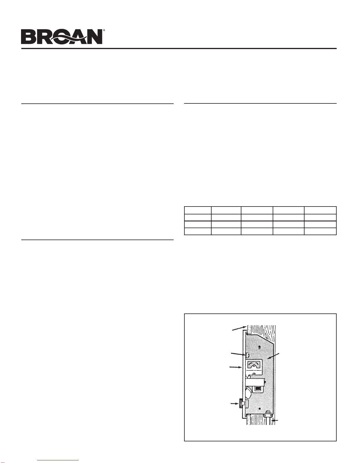
1 97009334 Housing
2 99390015 GroundingClip
3 99030190 FanDelay
4 98006989 ElementBracket (2Required)
5 99271155 HeatingElement(Model192)
99270723 HeatingElement(Model194)
99270724 HeatingElement(Model198)
6 99400061 Bushing
7 97008688 BlackWireAssembly(29–1/2")
8 97008690 BlackJumperWire
9 * ThermalOverloadBracket
10 * ThermalOverload
11 97008692 RedPowerWire
12 99150491 Screw,8–18x 3/8 Ph.PanHead
(14Required)
13 97008683 PartitionPlate Assembly
14 93270619 Wire Clamp (3Required)
15 99260425 Nut, 8–32HexKeps(2Required)
20 99160350 Screw,6–32x1/4Ph.PanHead
(2Required)
21 99030324 Thermostat
22 99080251 Motor(Model198)
23 99080249 Motor(Models192&194)
24 99020255 FanBlade
25 97013822 Grille
26 99150478 Screw,8–18x3/8PHTrussHd.
(4Required)
27 99090683 GrilleLogo
29 99360136 Knob
30 99110687 SecurityCover
31 93150462 Screw,8–18x5/8OvalHead(2Required)
* 97013945 Assembly,ThermalOverload(IncludesKey
Nos.9, 10,&12 (2))
PARTS LIST
BROAN-NUTONE ONE YEAR LIMITED WARRANTY
Broan-NuTonewarrantstotheoriginalconsumerpurchaser ofour
productsthatsuchproductswillbefreefromdefectsinmaterialsor
workmanshipforaperiodofoneyearfromdateoforiginalpurchase.
THEREARENOOTHERWARRANTIES,EXPRESSEDORIMPLIED,
INCLUDING,BUTNOTLIMITEDTO,IMPLIEDWARRANTIESOR
MERCHANTABILITYORFITNESSFORAPARTICULARPURPOSE.
Duringthisone-yearperiod,Broan-NuTonewill,atouroption,repair
orreplace,withoutcharge,any productorpartwhichisfoundtobe
defectiveundernormaluseandservice.
THISWARRANTYDOESNOTEXTENDTOFLUORESCENTLAMP
STARTERSANDTUBES.Thiswarrantydoesnotcover(a)normal
maintenanceand service or(b)any productsorparts which have
beensubjecttomisuse,negligence,accident,impropermaintenance
orrepair(otherthanbyus),faultyinstallationorinstallationcontrary
torecommendedinstallationinstructions.
Thedurationofanyimpliedwarrantyislimitedtotheone-yearperiod
asspecifiedfortheexpress warranty. Some states do not allow
limitationonhowlonganimpliedwarrantylasts,sotheabovelimita-
tionmaynotapplytoyou.
BROAN-NUTONE’SOBLIGATIONTOREPAIRORREPLACE,AT
OUROPTION, SHALL BETHEPURCHASER'SSOLE AND EX-
CLUSIVEREMEDYUNDER THIS WARRANTY.Broan-NuTone
SHALLNOTBELIABLEFORINCIDENTAL,CONSEQUENTIALOR
SPECIALDAMAGESARISINGOUTOFORINCONNECTIONWITH
PRODUCTUSEORPERFORMANCE.Somestatesdonotallowthe
exclusionorlimitationofincidentalorconsequentialdamages,sothe
abovelimitationsorexclusionmaynotapplytoyou.
Thiswarrantygivesyouspecificlegalrights,andyoumayalsohave
otherrights,whichvary from state to state. This warrantysuper-
sedesallpriorwarranties.
Toqualifyforwarrantyservice,youmust(a)notifyusatanaddress
ortelephonenumberbelow,(b) give the model number and part
identificationand(c)describethenatureofanydefectintheproduct
orpart.Atthetimeofrequestingwarrantyservice,youmustpresent
evidenceoftheoriginalpurchasedate.
Broan-NuTone LLC
926WestStateStreet
Hartford,WI53027
(1-800-637-1453)
WARRANTY
Productspecifications
subjectto change
withoutnotice.
99043273B
Call 1-800-667-8721 anywhere in the US and Canada - www.bathroomsource.com
::
bathroomsource
.
com
Broan at
::bathroomsource.com
is a division of
kitchen::
accessories
U N L I M I T E D
Other manuals for 192
2
This manual suits for next models
2
Table of contents
Other Broan Heater manuals

Broan
Broan QTX110HL User manual

Broan
Broan 9815WH SERIES User manual

Broan
Broan 164 User manual

Broan
Broan BHFLED80 User manual

Broan
Broan 170 User manual

Broan
Broan 192 User manual

Broan
Broan QTX110HL User manual

Broan
Broan QTX110HFLT User manual

Broan
Broan QTX110HFLT User manual

Broan
Broan 165FT User manual
Popular Heater manuals by other brands

Morso
Morso 1410 Installation and operating instructions

GOLDSUN
GOLDSUN AQUA GSA15 Installation and operation manual

cecotec
cecotec Ready Warm 5300 Power Box Ceramic instruction manual

Blumfeldt
Blumfeldt Ontario manual

Stadler Form
Stadler Form Max operating instructions

Levante
Levante LEVPH500TPSW Operation manual