manuals.online logo
Brands
  1. Home
  2. •
  3. Brands
  4. •
  5. Bticino
  6. •
  7. Switch
  8. •
  9. Bticino F67SR64 User manual

Bticino F67SR64 User manual

F67SR64
F6422B-WR-13W09
PROGRAM / EXCEPTION
The weekly and annual programs defined for a channel are not executed as long as an extra program is active.
However, other exception programs will be executed while an exception program is active.
The various exception programs are ORed together as described above. (see OR function 3a)
• The option EVERY YEAR should be selected if the exception program is to be activated for the same period in each year
(e.g. Christmas, national holidays, birthdays, etc.).
• The option ONCE should be selected if the exception program is to be activated only during a single period (e.g. vacation period), but the start
and end dates of this period are different in each year.
• Option MON TO SUN: the exception program is active from 00:00 hours on the start date to 24:00 hours on the end date.
During this period, the output of the related channel switches only as defined in the exception program.
• Option INDIVIDUAL: the exception program is active from 00:00 hours on the start date to 24:00 hours on the end date.
During this period, the output of the related channel switches only as defined in the exception program.
• Option PROG ON: the exception program is active from the ON time on the start date to OFF time on the end date. During this period, the output
of the channel is permanently on.
• Option PROG OFF: the exception program is active from the ON time on the start date to OFF time on the end date. During this period, the
output of the channel is permanently off.
Channel 2 is to be switched off each year for the entire period 01.08. to 31.08.

Each year from 25.12. to 26.12., channel 2 is to be switched on at 6:00 hours, switched off at sunrise, switched on at sunset and switched
off at 23:00 hours. For this, two programs are needed:
Program 1: ON at 6:00 and OFF at sunrise
Program 2: ON at sunset and OFF at 23:00

Sample EXCEPTION programs
PROGRAM
Edit/Check/Delete
3C
3D
Overview
Day, time, date
Switch state
Function
Channel
number
Socket for
data key
Ref. F68K
Separate
manual switch
for each
channel
One-week overview of the
programmed switching times.
Resolution: 0.5 h
Menu selection, back in menu,
Actuation >1s = operating display
Confirm a selection or accept
a parameter setting
• Selection of a menu item
or set a parameter.
• Channel selection
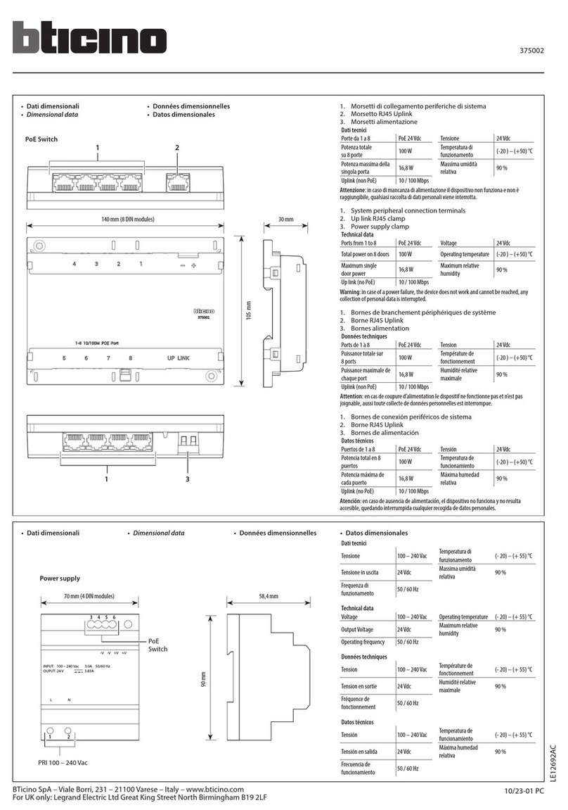
Safety notes This product may be installed only by a qualified electrician. Non-compliance may result in a fire hazard or electric shocks. Before installation, read the operating
instructions and observe the product-specific requirements for the installation location. Use only original spare parts for repair and maintenance. All Legrand products may be
opened and repaired only by specially trained Legrand personnel. Unauthorised opening and repair by other persons will invalidate all claims for liability, replacement or warranty
services. When operated from the mains voltage, the time switch may not be used to switch safe extra-low voltages (SELV). When operated from a safe extra-low voltage, it may
not be used to switch mains voltages. When The device contains a Li-SOCl2 cell. When the product reaches the end of its life, this cell must be correctly removed and disposed
of in accordance with national legislation and the requirements of environmental protection.operated from a safe extra-low voltage, it may not be used to switch mains voltages.
Supply voltage: 120 / 230V 50/60Hz Delay time: 0 … 23 h 59 min 59 s
Power consumption: approx. 0,3…2 W Local coordinates: Risoluzione 1°
Relay outputs 1- 4: 4 changeover contacts 16A 250V~ cos ϕ = 1 Battery reserve: 5 anni
Accuracy: ± 0,2 s/day under typical installation conditions
Storage temperature:
da - 20°C a +60°C
single-strand Operating principle:
Typ 1.B. S. T. IEC/EN 60730-2-7
Wire cross-sections: 1,5...4 mm2Operation in a normal environment
Programs 4 channels x 3 program types x 28 programs
Degree of contamination:
2
Control signal for channel 1: supply voltage, referred to neutral Installation: in distribution panel
Control-pulse duration: > 200ms
Control-wire length: max. 50m
Technical data
+
+
+
c
3600W 1800W 100W 1800W 1800W 2300W 1400VA 1x 58W 7uF
N292244/05
PROGRAM / YEAR
This menu item permits the input of (additional) annual programs which are to be executed only during a specified period. These programs and the
weekly programs of the same channel are ORed together as described above.
The period during which a program is to be executed is defined by entering a start date and an end date.
• The option EVERY YEAR should be selected if the additional program is to be executed during the same period of each year
(e.g. Christmas, national holidays, birthdays, etc.).
• The option ONCE should be selected if the additional program is to be executed only during a single period (e.g. vacation period), but the
start and end dates of this period are different in each year.
Sample YEAR program
Channel 2 is to be activated each year on at 09:00 hours on 01.11. and deactivated at 23:00 hours.
PROGRAM / WEEK
This menu item is provided for the simple input of programs which are to be repeated weekly (such as switching of lights and boilers).
A weekly program consists of an ON time, an OFF time and the associated ON and OFF days.
• MON TO SUN: the days of the week are already assigned and you only need to set the ON and OFF times. This is used where the same pro-
gram is to be executed on every day of the week.
• INDIVIDUAL: you can assign the ON and OFF times to any desired days. This is used where the same program is to be executed only on
certain days of the week or different programs are to be executed on the various days.
OR function
The programs defined for each channel are ORed together. In other words, the output will be active if this is defined in any of the programs.
Example: channel 1
Sample WEEK program
The timer is to switch on at sunset on each day of the week and switch off at sunrise.
ON at sunset
OFF at sunrise
ON / OFF at programmed time
Prog 1
Prog 2
Channel-1 relay
3A
3B
General information
• Starting: After connection of the supply voltage, the clock
starts to run with the last selected function. The relay
position is determined by the currently active program.
• Backup battery operation mode:
- background lighting not available.
- data key READ/WRITE only via the menu.
• If, during programming, no key is pressed for 60 seconds,
the timer automatically switches from the menu display to
the normal operating display.
Select language

Factory setting: 8°E 52°N
The MINUS key is used to adjust the westward longitude value in the range
from 000°EAST/WEST to 180°WEST.
The PLUS key is used to adjust the eastward longitude value in the range
from 000°EAST/WEST to 180°EAST.
The PLUS key is used to adjust the northward latitude value in the range from
00°NORTH/SOUTH to 90°NORTH.
The MINUS key is used to adjust the southward latitude value in the range from
00°NORTH/SOUTH to 90°SOUTH.
0h 3 6 9 12 15 18
21 24h
t
1
0
++
max. 120min
max. 120min
The time switch switches on at the calculated sunset time and off at the calculated sunrise time.
By setting an offset, you can shift the switching times by up to ±120 minutes with respect to the calculated sunrise and
sunset times.
Example:
If you set the offset to +30 minutes, the time switch will switch 30 minutes after sunrise and 30 minutes after sunset.
If you set the offset to -30 minutes, the time switch will switch 30 minutes before sunrise and 30 minutes before
sunset.
Seting

Astro
C
Offset
D
Time and date
A
Use the enclosed time-zone map to set
the correct time zone.
From this map, determine the difference
between local time and UTC (Universal Time
Coordinated) and set this value.
Select country.
Select the city
closest to the
planned location
for use.
You can adjust the coordinates
more precisely with
LONGITUDE and
LATITUDE.
Summer time +1h
BEurope: factory setting.
Special: The dates for switching to
and from summer time can be set
as desired by entering a start date
and end date. In the following years,
switching will be carried out on the
corresponding day of the week (e.g.
Sunday).
F68K
• Data key (F68K)
• Operating-hours counter
• This displays the total duration of the ON times, from
0 to 065535 hours, and the date on which this counter
was last reset.
• Contrast adjustment
• Load the programs from the data key to the time switch (READ KEY)
Warning! all programs already programmed in the time switch will be overwritten.
• Load the programs of the time switch on to a data key (WRITE KEY)
Warning! all programs already existing on the data key will be overwritten.
• or
• or
F68K
Reset
• 1 h test

• Note!
A reset clears the entire memory, which means that all previously set data will be lost.
Press and hold all four keys together for about 2 seconds, then release them.
After a reset, the language, time and date, summertime, coordinates, time zone,
switching times and pin code must be set again.
Example
• PINCODE ACTIVE: the PINCODE must be entered before the time switch can be operated.
The access protection can be cancelled by selecting PASSIVE. It is also cancelled by a reset.
• If this menu item is activated, the outputs are switched on for one hour.
The test can be terminated at any time by selecting the option PASSIVE.
Pincode (access protection)
0 ... 23h 59min 59s
0 … 23h 59min 59s
• Important note:
If the battery is replaced with the supply voltage connected, all stored program data are retained. If the battery is replaced
with the supply voltage disconnected, the date and time must be set again. Notes for disposal of the lithium battery:
Dispose of the exhausted battery in accordance with your local regulations. Make sure the battery is fully discharged before
disposal.
• Control input with delaytime
• The control signal affects only channel 1 and overrides all program settings for this channel (OR function). Channel 1 remains switched on as along
as the control signal is present. If the function CYCLE is selected under SETUP, channel 1 is switched on and off cyclically.
When the control signal is switched off, the output of channel 1 switches off after the defined delaytime, unless one of the programs for this channel
specifies otherwise.
• Setting the delaytime
• Delaytime
• Switched output
• Control input
• Changing the lithium battery module
0:10:00 0:10:00 0:10:00
0:04:00 0:04:000:04:00
15:00:00 15:10:00 15:20:00 15:30:00
15:32:00
• Instead of its STANDARD function, the output of channel 1 is switched on and off cyclically.
The available parameters are the PERIOD and the PULSE-TIME within this period
Program channel 1,
or control signal S
Channel-1 relay
PERIOD
PULSE-TIME PULSE-TIME PULSE-TIME
PERIOD PERIOD
• Extended Settings
• senza funzione
• The data interface KEY is preset and cannot be changed
• The default setting is PASSIVE. In order to improve the accuracy, it is advisable to
activate this synchronisation with the mains frequency (50/60 Hz).
• Activating and deactivating mains synchronisation.
min max
PERIOD 2 s 2h
PULSE-TIME 1 s 1h 59min 59s
• Cycle function for channel 1
PA RT. F6637B Instruction sheet 11/12-01 WR
F67SR64
PA RT. F6637B Instruction sheet 11/12-01 WR
F67SR64

Other Bticino Switch manuals

Bticino Classia W4411CM2 User manual

Bticino

Bticino Classia W4411CM2 User manual

Bticino 335828 User manual

Bticino

Bticino 335828 User manual

Bticino K4574CWI User manual

Bticino

Bticino K4574CWI User manual

Bticino AM4510C User manual

Bticino

Bticino AM4510C User manual

Bticino K4411C User manual

Bticino

Bticino K4411C User manual

Bticino K4413CM2 User manual

Bticino

Bticino K4413CM2 User manual

Bticino RW4411CM2 User manual

Bticino

Bticino RW4411CM2 User manual

Bticino LIVINGLIGHT N4574CW User manual

Bticino

Bticino LIVINGLIGHT N4574CW User manual

Bticino QMT Series User manual

Bticino

Bticino QMT Series User manual

Bticino 323002 User manual

Bticino

Bticino 323002 User manual

Bticino K4003CWI User manual

Bticino

Bticino K4003CWI User manual

Bticino L4411C User manual

Bticino

Bticino L4411C User manual

Bticino RW4027C User manual

Bticino

Bticino RW4027C User manual

Bticino BTK4003CWI User manual

Bticino

Bticino BTK4003CWI User manual

Bticino RW4003C User manual

Bticino

Bticino RW4003C User manual

Bticino K4411CM2 User manual

Bticino

Bticino K4411CM2 User manual

Bticino LIVING NOW K4001C User manual

Bticino

Bticino LIVING NOW K4001C User manual

Bticino LIVINGLIGHT N4570CW User manual

Bticino

Bticino LIVINGLIGHT N4570CW User manual

Bticino Livinglight 3577C User manual

Bticino

Bticino Livinglight 3577C User manual

Bticino F67SR11 User manual

Bticino

Bticino F67SR11 User manual

Bticino LIVING NOW K4574CW User manual

Bticino

Bticino LIVING NOW K4574CW User manual

Bticino AM4531C User manual

Bticino

Bticino AM4531C User manual

Bticino HA48 VNN Series User manual

Bticino

Bticino HA48 VNN Series User manual

Bticino L4413CM2 User manual

Bticino

Bticino L4413CM2 User manual

Popular Switch manuals by other brands

TSi Power ATS-1000 operating manual

TSi Power

TSi Power ATS-1000 operating manual

Agilent Technologies 34950A user guide

Agilent Technologies

Agilent Technologies 34950A user guide

steute RF 10 SW868 Mounting and wiring instructions

steute

steute RF 10 SW868 Mounting and wiring instructions

steute ZS 80 Mounting and wiring instructions

steute

steute ZS 80 Mounting and wiring instructions

GarrettCom Magnum S14 Installation and user guide

GarrettCom

GarrettCom Magnum S14 Installation and user guide

Rose electronics QuadraVista Installation and operation manual

Rose electronics

Rose electronics QuadraVista Installation and operation manual

ADTRAN 600 Series Interface guide

ADTRAN

ADTRAN 600 Series Interface guide

Lindy 32488 user manual

Lindy

Lindy 32488 user manual

Edimax ES-3116RE+ user manual

Edimax

Edimax ES-3116RE+ user manual

Grundfos IO 50 SQFlex Installation and operating instructions

Grundfos

Grundfos IO 50 SQFlex Installation and operating instructions

Ruijie RG-SF2920U Series Hardware  installation and reference guide

Ruijie

Ruijie RG-SF2920U Series Hardware installation and reference guide

Linksys SRW2008 user guide

Linksys

Linksys SRW2008 user guide

Raven Slingshot Field Hub troubleshooting guide

Raven

Raven Slingshot Field Hub troubleshooting guide

Cisco Linksys SE1500 user guide

Cisco

Cisco Linksys SE1500 user guide

TRENDnet TEG-S18TX user guide

TRENDnet

TRENDnet TEG-S18TX user guide

Cabletron Systems SmartSTACK EPIM1000-S1LX 1000BASE-LX Quick installation guide

Cabletron Systems

Cabletron Systems SmartSTACK EPIM1000-S1LX 1000BASE-LX Quick installation guide

Kontron ETX CD user guide

Kontron

Kontron ETX CD user guide

Flowserve F5 User instructions

Flowserve

Flowserve F5 User instructions

manuals.online logo
manuals.online logoBrands
  • About & Mission
  • Contact us
  • Privacy Policy
  • Terms and Conditions

Copyright 2025 Manuals.Online. All Rights Reserved.