Bticino 365711 User manual

365711 - 365721
Video Kit
Manuale installatore • Installation manual
LE07588AA-1PC-15W03

2

Video Kit
3
• Vecchio impianto a campanello
Impianto esistente con 3 fili e sola chiamata.
• Old system with bell
Existing system with 3 wires and just call.
• Ancienne installation a sonnette
Installation existante à 3 fils et un seul appel.
• Alte klingelanlage
Vorhandene 3-Leiter Anlage nur mit Ruffunktion.
• Vieja instalación con timbre
Instalación existente con 3 hilos y una llamada.
• Oude deurbelinstallatie
Bestaande 3-aderige installatie met alleen een
oproepfunctie.
• Antiga instalação em campaínha
Instalação existente com 3 fios e somente
chamada.
230 Vac 12 V
230 Vac
}
34 6 0 0 0
032206
IP30
PRI230V~50 - 60Hz 260mA
BUS
2-1 27V 1,2A
PRI
PS
BUSTK BUS P I
346830
230 Vac 12 V
230 Vac
}
34 6 0 0 0
032206
IP30
PRI230V~50 - 60Hz 260mA
BUS
2-1 27V 1,2A
PRI
PS
BUSTK BUS P I
346830
230 Vac 12 V
230 Vac
}
34 6 0 0 0
032206
IP30
PRI230V~50 - 60Hz 260mA
BUS
2-1 27V 1,2A
PRI
PS
BUSTK BUS P I
346830
• Nuovo impianto citofonico
Impianto realizzato senza modifiche ai 2 fili
esistenti: chiamata, videocitofono e serratura.
• New door entry system
System made without modifications to the 2 existing
wires; call, video handset and electric door lock.
• Nouvelle installation phonique
Installation réalisée sans modifications sur les 2 fils
existants: appel, vidéophone, et serrure électrique.
• Neue haustelefonanlage
Anlage ohne Änderungen an den vorhandenen 2 Leiter:
Ruffunktion, Gegensprechanlage und elektrisches Schloss.
• Nueva instalación interfónica
Instalación realizada sin las modificaciones a los 2 hilos
existentes: llamada, videoportero y cerradura eléctrica.
• Nieuwe deurtelefooninstallatie
Installatie aangelegd zonder wijzigingen aan de
2 bestaande aders: oproep, beeldhuistelefoon en
elektrisch deurslot.
• Nova instalação do intercomunicador
Instalação realizada sem modificar os 2 fios existentes:
chamada, intercomunicador vídeo e fechadura eléctrica.

4
D
B C
A
IP30
PRI
PRI 230 V~ 50 - 60 Hz 260 mA
346000
}
BUS
2 - 1 27V 1,2A
CEBEC
N
N
F
>0,2 mm2
BTicino
L4669
0,35 mm20,28 mm2
BTicino
C9881U/5E
AWG24 UTP5
BTicino
336904
One PTT
278TP
0,28 mm2
OneSYT
+ Digital
TP
5/10
OneSYT
+ NumTP
5/10
GIGATW
CAT5E
AWG24
One SYT
+ NumTP
8/10
Cable
ARB.6060-1
6/10
Cable
EV6R
6/10
1
mm2
A 50 m 140 m 145 m 200 m 200 m 150 m 200 m 50 m –
B 50 m 115 m 80 m 200 m 115 m 80 m 200 m 50 m –
C 50 m 130 m 80 m 200 m 100 m 80 m 200 m 50 m –
D 30 m 30 m – 50 m 30 m – – – 100 m
• Cavi e distanze (mm2)
• Cables and distances (mm2)
• Câbles et distances (mm2)
• Kabeln und Abstände (mm2)
• Cables y distancias (mm2)
• Kabels en afstanden (mm2)
• Cabos e distâncias (mm2)

Video Kit
5
•
Schema monofamigliare (366711)
•
One-family diagram (366711)
•
Schéma mono-familial (366711)
•
Schema Einfamilienhaus (366711)
•
Esquema monofamiliar (366711)
•
Schema eensgezins (366711)
•
Esquema monofamiliar (366711)
BUS
PL S+S-
PS
BUS TK BUS PI
346830
BUS 2 1
230 Vac
IP30
PRI
PRI 230V~ 50 - 60 Hz 260mA
346000
}
BUS
2 - 1 27V 1,2A
CEBEC
N
N
F
N= –
= –
T = –
S = –
P= –
–
=
A
ON
OFF
P= –
= –
= –
= –
M
J2
J1
N= –
= –
BUS
B
•APulsante apertura serratura.
BChiamata al piano.
S+ S- 18V; 4 A impulsivi. 250 mA mantenimento (30 Ω max).
•ADoor lock pushbutton.
BFloor call.
S+ S- 18 V; 4 A impulsive. 250 mA holding current (30 Ω max).
•APoussoir d’ouverture serrure.
BAppel à l’étage.
S+ S- 18V; 4 A impulsifs. 250 mA entretien (30 Ω max).
•ASchalter Türöffner.
BEtagenruf.
S+ S- 18 V; 4 A impulsstrom. 250 mA Haltestrom (30 Ω max).
•APulsador de apertura de cerradura.
BLlamada al piso.
S+ S- 18V; 4 A por impulsos. 250 mA mantenimiento (30 Ω max).
•ADrukknop opening.
BOproep aan verdieping.
S+ S- 18 V; 4 A impulsief; 250 mA onderhoud (30 Ω max).
•ABotão para abertura do trinco.
BChamada ao piso.
S+ S- 18V; 4 A instantâneos. 250 mA continuos (30 Ω max).

6
• Schema bifamigliare 1 (366721)
• Two-family diagram 1 (366721)
• Schéma bi-familiale 1 (366721)
• Schema Zweifamilienhaus 1 (366721)
• Esquema bifamiliar 1 (366721)
• Schema tweegezins 1 (366721)
• Esquema bifamiliar 1 (366721)
BUS
PL S+S-
PS
BUS TK BUS PI
346830
BUS 2 1
230 Vac
IP30
PRI
PRI 230V~ 50 - 60 Hz 260mA
346000
}
BUS
2 - 1 27V 1,2A
CEBEC
N
N
F
A
N= –
= –
T = –
S = –
P= –
–
=
ON
OFF
ON
OFF
BUS
B
BUS
B
P= –
= –
= –
= –
M
J2
J1
N= –
= *1
P= –
= –
= –
= –
M
J2
J1
N= –
= –
* • Inserire il configuratore fornito a corredo.
• Connect the configurator supplied as standard.
• Mettre en place le configurateur fourni à cet effet.
• Den mitgelieferten Konfigurator einsetzen.
• Inserte el configurador suministrado.
• Breng de standaard geleverde configurator aan.
• Inserir o configurador fornecido no equipamento base.
•APulsante apertura serratura.
BChiamata al piano.
S+ S- 18V; 4 A impulsivi. 250 mA mantenimento (30 Ω max).
•ADoor lock pushbutton.
BFloor call.
S+ S- 18 V; 4 A impulsive. 250 mA holding current (30 Ω max).
•APoussoir d’ouverture serrure.
BAppel à l’étage.
S+ S- 18V; 4 A impulsifs. 250 mA entretien (30 Ω max).
•ASchalter Türöffner.
BEtagenruf.
S+ S- 18 V; 4 A impulsstrom. 250 mA Haltestrom (30 Ω max).
•APulsador de apertura de cerradura.
BLlamada al piso.
S+ S- 18V; 4 A por impulsos. 250 mA mantenimiento (30 Ω max).
•ADrukknop opening.
BOproep aan verdieping.
S+ S- 18 V; 4 A impulsief; 250 mA onderhoud (30 Ω max).
•ABotão para abertura do trinco.
BChamada ao piso.
S+ S- 18V; 4 A instantâneos. 250 mA continuos (30 Ω max).

Video Kit
7
BUS
PL S+S-
PS
BUS TK BUS PI
346830
BUS 2 1
230 Vac
IP30
PRI
PRI 230V~ 50 - 60 H z 260 mA
346000
}
BUS
2 - 1 27V 1,2A
CEBEC
N
N
F
A
N= –
= –
T = –
S = –
P= –
=
ON
OFF
ON
OFF
BUS
B
BUS
B
P= –
= –
= –
= –
M
J2
J1
N= –
= *1
P= –
= –
= –
= –
M
J2
J1
N= –
= –
* • Inserire il configuratore fornito a corredo.
• Connect the configurator supplied as standard.
• Mettre en place le configurateur fourni à cet effet.
• Den mitgelieferten Konfigurator einsetzen.
• Inserte el configurador suministrado.
• Breng de standaard geleverde configurator aan.
• Inserir o configurador fornecido no equipamento base.
• Schema bifamigliare 2 (366721)
• Two-family diagram 2 (366721)
• Schéma bi-familiale 2 (366721)
•
Schema Zweifamilienhaus 2 (366721)
• Esquema bifamiliar 2 (366721)
• Schema tweegezins 2 (366721)
• Esquema bifamiliar 2 (366721)

8
• Opzione serratura a relè
• Relay door lock option
• Option serrure à relais
• Option Relais-Schloss
• Opción cerradura de relé
• Optie relaisslot
• Opção trinco de relê
•APulsante apertura serratura.
S+ S- 18V; 4 A impulsivi. 250 mA mantenimento (30 Ω max).
•ADoor lock pushbutton.
S+ S- 18 V; 4 A impulsive. 250 mA holding current (30 Ω max).
•APoussoir d’ouverture serrure.
S+ S- 18V; 4 A impulsifs. 250 mA entretien (30 Ω max).
•ASchalter Türöffner.
S+ S- 18 V; 4 A impulsstrom. 250 mA Haltestrom (30 Ω max).
•APulsador de apertura de cerradura.
S+ S- 18V; 4 A por impulsos. 250 mA mantenimiento (30 Ω max).
•ADrukknop opening.
S+ S- 18 V; 4 A impulsief; 250 mA onderhoud (30 Ω max).
•ABotão para abertura do trinco.
S+ S- 18V; 4 A instantâneos. 250 mA continuos (30 Ω max).
BUS
PL S+S-
A
N= –
= –
T = –
S = –
P= –
–
=
8 A cosφ = 1
4 A cosφ = 0,7
3 A cosφ = 0,4
24 Vdc; 24 Vac
24 Vac
24 Vac
NO
NC
C
346250 (*)
S- S+ CNC NO
* • Fornito a corredo.
• Supplied.
• Fourni.
• Wird mitgeliefert.
• En dotación.
• Standaard meegeleverd.
• Fornecido no equipamento base.

Video Kit
9
• Altezza consigliata salvo diversa normativa vigente.
• Recommended height, unless different regulations are specified.
• Hauteur conseillée sauf autre norme en vigueur.
• Empfohlene Höhe falls die gesetzlichen Vorschriften nichts
anderes vorschreiben.
• Altura recomendada salvo normativa vigente diferente.
• Aanbevolen hoogte behoudens andere normen in voege.
• Altura aconselhada a não ser se a norma em vigor for diferente.
160 – 165 cm
135–140 cm
• Dati dimensionali
• Dimensional data
• Données dimensionnelles
• Maße
• Datos dimensionales
• Formaatgegevens
• Dados dimensionais
35 mm
106 mm
185 mm
194 mm
162 mm
25 mm
115 cm 50 cm
240 cm
• Campo di ripresa
• Field of view
• Éclairage cadrage
caméra
• Aufnahmebereich
• Campo de filmación
• Campo de filmagem
• Opnameveld

10
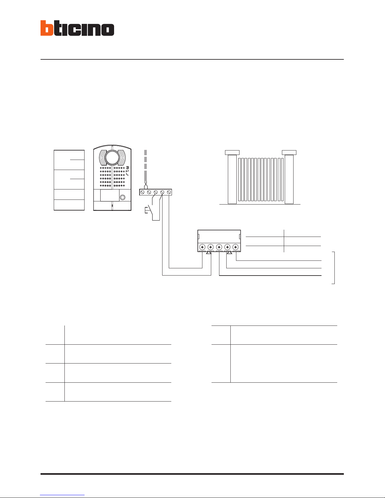
1 - Activação/desactivação do sinal de confir-
mação da abertura da fechadura.
2 - Regulação do volume
(*veja as próxima
página).
3 - Indicadores luminosos verde: indicação de
porta aberta.
4 - Indicadores luminosos verde: comunicação
activa.
5 - Indicador luminoso lampejante Verde:
chamada enviada; Indicador luminoso lam-
pejante Vermelho: sistema cupado.
6 - Alojamento configurador.
• Posto esterno
• Entrance panel
• Poste extérieur
• Türstation
• Placa exterior
• Externe plaats
• Unidade externa
1 - Habilitación/deshabilitación del tono de
confirmación de apertura de la cerradura.
2 - Regulación del volumen (*véase la pág.
siguiente).
3 - Led verde: indicación puerta abierta.
4 - Led verde: comunicación activada.
5 - Led parpadenate Verde: llamada enviada;
Led parpadenate Rojo: sistema ocupado.
6 - Alojamiento configuradores.
1 - Enabling/disabling of door lock opening confir-
mation tone.
2 - Adjustment volume (*see the following page).
3 - Green LED: door open indication.
4 - Green LED: communication active.
5 - Green flashing LED; call forwarded;
Red flashing LED: system busy.
6 - Configurator seat.
1 - Abilitazione/disabilitazione tono conferma
apertura serratura.
2 - Regolazione del volume (*vedi pag. seguente).
3 - Led verde: indicazione porta aperta.
4 - Led verde: comunicazione attiva.
5 - Led lampeggiante Verde: chiamata inoltrata;
Led lampeggiante Rosso: sistema occupato.
6 - Sede configuratori.
1 - Aktivierung/Deaktivierung des Bestätigungs-
signals nach erfolgter Türöffnung.
2 -
Einstellung der Lautstärke (*siehe nachfolgende
Seiten).
3 - Grüne Led: Meldet offene Tür.
4 - Grüne Led: Kommunikation aktiv.
5 - Grüne blinkende Led: Ruf gesendet;
Rote blinkende Led: System belegt.
6 - Sitz der Konfiguratoren.
1 - Activation/désactivation tonalité de confirma-
tion ouverture serrure.
2 - Réglage du volume (* voir page suivante).
3 - Diode verte: indication porte ouverte.
4 - Diode verte: communication active.
5 - Témoin clignotant vert - appel passé;
Témoin clignotant rouge: système occupé.
6 - Logement configurateurs.
1 - Activering/desactivering toon bevestiging
opening slot.
2 - De geluidssterkte regelen
(*zie de volgende
pagina’s).
3 - Groene led: aanduiding open deur.
4 - Groene led: communicatie actief.
5 - Groene knipperende led: oproep doorge-
stuurd; Rode knipperende led: systeem bezet.
6 - Plaats van de configuratiemodules.
ON OFF
3
4
5
1
6
2

Video Kit
11
(*)
• Se si manifestasse il disturbo del fischio, (effetto Larsen), ridurre prima la potenza del microfono , agen-
do con un cacciavite sul potenziometro corrispondente, fino ad un livello accettabile. Qualora il fenomeno
persista, agire sul potenziometro dell’altoparlante in modo da eliminare l’inconveniente. Se il volume è
troppo basso, aumentare prima il volume dell’altoparlante ed eventualmente anche quello del microfono,
tenendo presente che è preferibile una trasmissione chiara e priva di disturbi, che una al limite dell’innesco
(Larsen).
• In case of a whistle (Larsen effect), first reduce the microphones power, adjusting the corresponding
potentiometers with a screw driver, until an acceptable level is reached. Should the whistle persist, adjust the
loudspeakers volume in order to eliminate the trouble. If the volume is too low level then, increase first the
potentiometer of the loudspeaker and secondly the one for the microphone, bearing in mind that a clear and
noise free reception is preferable than one just before whistling (Larsen).
• Lors de sifflement (effet de Larsen), reduire d’abord la puissance du micro sur le potentiomètre corres-
pondant, à l’aide d’un tournevis, jusqu’à l’obtention d’un niveau satisfaisant. Si le sifflement persiste, régler
le potentiomètre du hautparleur jusqu’à l’élimination de celui-ci. Si le volume est trop bas, augmenter
d’abord la puissance du haut-parleur et éventuellement celle du micro, en considérant qu’une réception
claire et sans parasite est préférable à une communication à la limite de l’accrochage (effet de Larsen).
• Beim etwaigen Auftreten eines Pfeiftones (Larsen-Effekt), zuerst die Lautstärke des Mikrophones bis auf einen
annehmbaren Wert herabsetzen, indem man das entsprechende Potentiometer mit einem Schraubendreher
einstellt. Sollte die Störung weiterhin bestehen, dann das Potentiometer des Lautsprechers bis zur Beseitigung
des Pfeiftones einstellen. Ist die Lautstärke nun zu niedrig, dann zuerst die des Lautsprechers und erst danach
evtl. auch die des Mikrophones erhohen, wobei ein deutlicher und störungsfreier Empfang einem an der
Störungsgrenze liegendem (Larsen-Effekt) vorzuziehen ist.
•Si se manifesta el silbido de acoplamiento, (efecto Larsen), reducir primero la potencia del micrófono
, girando con un destornillador el potenciómetro correspondiente, hasta obtener un nivel aceptable. Si el
fenómeno persistiera, regular el potenciómetro del altavoz hasta eliminar la interferencia. Si el volumen
es demasiado bajo, aumentar primero el volumen del altavoz y eventualmente también el del micrófono,
teniendo en cuenta que es preferible una transmissión clara y limpia de interferencias, que una al limite del
acoplo (Larsen).
• Als er een fluittoon hoorbaar is (effect van Larsen): verminder eerst het vermogen van de microfoon
met behulp van een schroevendraaier zijn stroomregelaar zo te regelen dat de geluidssterkte van het gefluit
aanvaardbaar is. Als het verschijnsel niet verdwijnt, dan moet u ook de stroomregelaar van de luidspreker
bijstellen. Als de geluidssterkte nu te klein is, verhoog dan eerst de geluidssterkte van de luidspreker en daarna
eventueel ook die van de microfoon, en denk er bij het bijstellen aan dat een duidelijk hoorbaar en ongestoord
geluid beter is dan een harder geluid op de grens van het Larsen effect.
• Se se manifestar uma interferência no som (efeito de Larsen), começar por diminuir a potência do microfone
, rodando o potenciómetro correspondente com uma chave de parafusos, até obter um nível aceitável.
Se o fenómeno persistir, regular o potenciómetro do altifalante de modo a eliminar o problema. Se o
volume estiver demasiado baixo, começar por aumentar o volume do altifalante e depois, se necessário,
o do microfone, tendo presente que é melhor ter uma transmissão clara e sem interferências, que uma no
limiar de início de efeitos Larsen.

12
• Posto interno
• Handset
18
21
22
2323
19
20
24252627
1 2 3 4 5 76
16
15
14
17
91011
12
139
8

Video Kit
13
L’immagine rappresenta il dispositivo con
tutte le funzioni abilitate. Verifica sul manuale
installatore come abilitare le funzioni.
1 - Display 7”(16 : 9)
2 - Tasto spegnimento
3 - Data e ora
4 - Esclusione suoneria
5 - Attivazione Studio professionale
6 - Microfono
7 - Attivazione Segreteria
8 - Azioni rapide
9 - Guide tattili per non vedenti
10 - Tasto connessione:
l’accensione del led verde lampeggiante indica
una chiamata in arrivo
l’accensione del led verde fisso indica la
comunicazione in corso
11 - Autoaccensione/Ciclamento:
alla pressione del tasto il LED rosso si accende
12 - Tasto Preferiti:
alla pressione del tasto il LED rosso si accende
(Configurazione base = LUCE SCALE. Per una
diversa configurazione fare riferimento alla tabella
della configurazione fisica alle pagine successive.)
13 - Tasto apertura serratura:
alla pressione del tasto il LED rosso si accende
14 - Stato Segreteria:
Led rosso fisso = segreteria attiva
Led rosso lampeggiante = presenza registrazione/i
non visionata/e
15 - Stato presenza note:
Led rosso lampeggiante = nuova/e note non lette
16 - Stato Esclusione chiamata:
Led rosso acceso = Suoneria chiamata disattivata
17 - Funzioni (compaiono solo le icone delle funzioni
configurate)
18 - Sede dei configuratori
19 - Configuratore J1: estrai per alimentazione
supplementare
20 - Configuratore J2: Master/Slave, estrai per Slave
21 - Microinterruttore ON/OFF di terminazione di
tratta
22 - Presa mini USB per aggiornamento Firmware
dispositivo
23 - Altoparlante
24 - Morsetti (1 - 2) per alimentazione supplementare
25 - Morsetti per il collegamento al BUS SCS 2 FILI
26 - Morsetti ( ) per il collegamento di un pulsante
esterno di chiamata al piano
27 - Morsetti (1 - 5M) per il collegamento di una
suoneria supplementare. Devi effettuare il
collegamento punto - punto sui morsetti delle
suonerie supplementari
The image shows the device with all its
functions enabled.
Check on the Installer Manual how to enable
the functions.
1 - 7”(16 : 9) display
2 - OFF key
3 - Date and time
4 - Bell exclusion
5 - Office activation
6 - Microphone
7 - Answering machine activation
8 - Quick actions
9 - Tactile guides for the blinds
10 - Connection key:
The green LED flashes to indicate an incoming call
The green LED comes on steady to indicate that
there is an active call
11 - Auto-switching on/Cycling:
The red LED turns on when the key is pressed
12 - Favorites Key:
The red LED turns on when the key is pressed
(Basic configuration = STAIRCASE LIGHT. For
a different configuration refer to the physical
configuration table in the following pages.)
13 - Door lock release key:
The red LED turns on when the key is pressed
14 - Answering machine Status:
Red LED steady = answering machine active
Red LED flashing = new recording/s
15 - Message status:
Red LED flashing = new unread note/s
16 - Call Exclusion Status:
Red LED on = Call bell disabled
17 - Functions (only the icons for the configured
functions are displayed)
18 - Configurator seat
19 - Configurator J1: remove for additional power
supply
20 - J2 configurator: Master/Slave, remove for Slave
21 - Line termination ON/OFF micro-switch
22 - Mini USB socket for device Firmware update
23 - Loudspeaker
24 - Additional power supply clamps (1 - 2)
25 - 2 WIRE SCS/BUS connection clamps
26 - Clamps ( ) for the connection of an external
call to the floor pushbutton
27 - Additional bell connection clamps (1 - 5M) Point-
to-Point connections are required on the clamps
of the additional bells

14
• Poste interne
• Hausstation
18
21
22
2323
19
20
24252627
1 2 3 4 5 76
16
15
14
17
91011
12
139
8

Video Kit
15
L’image représente le dispositif avec toutes les
fonctions activées.
Vérifier dans le Manuel Installateur le mode
d’activation des fonctions.
Das Bild stellt eine Vorrichtung mit allen
aktivierten Funktionen dar.
Sehen Sie im Installationshandbuch nach, wie
die Funktionen aktiviert werden.
1 -
Écran 7”(16:9)
2 -
Touche d’extinction
3 -
Date et heure
4 -
Exclusion sonneries
5 -
Activation Bureau
6 -
Micro
7 -
Activation Répondeur
8 -
Actions rapides
9 -
Guides tactiles pour non-voyants
10 -
Touche connexion :
l’allumage du voyant vert clignotant indique la
présence d’un appel entrant
l’allumage du voyant vert fixe indique la
communication en cours
11 -
Auto-allumage/Cyclage :
à la pression sur la touche le VOYANT rouge s’allume
12 -
Touche Favoris :
à la pression sur la touche le VOYANT rouge s’allume
(Configuration de base = LUMIÈRE ESCALIER. Pour
une configuration différente, faire référence au
tableau de la configuration physique dans les pages
suivantes.)
13 -
Touche d’ouverture serrure:
à la pression sur la touche le VOYANT rouge s’allume
14 -
État Répondeur:
Voyant rouge fixe = répondeur activé
Voyant rouge clignotant = présence
enregistrement(s) non visionné(s)
15 -
État présence notes :
Voyant rouge clignotant = nouvelle(s) note(s) non
lue(s)
16 -
État Exclusion appel:
Voyant rouge allumé = Sonnerie appel désactivée
17 -
Fonctions (seules les icônes des fonctions
configurées s’affichent)
18 -
Logement configurateurs
19 -
Configurateur J1 : extraire pour alimentation
supplémentaire
20 -
Configurateur J2: Master/Slave, extraire pour Slave
21 -
Microinterrupteur ON/OFF de terminaison de ligne
22 -
Prise miniUSB de mise à jour Firmware dispositif
23 -
Haut-parleur
24 -
Bornes (1 – 2) d’alimentation supplémentaire
25 -
Bornes de branchement au BUS SCS 2 FILS
26 -
Bornes ( ) de branchement d’un bouton externe
d’appel à l’étage
27 -
Bornes (1 - 5M) de branchement d’une sonnerie
supplémentaire Le branchement doit être
effectué point - point sur les bornes des sonneries
supplémentaires
1 -
Display 7”(16 : 9)
2 -
Ausschalttaste
3 -
Datum und Uhrzeit
4 -
Ausschluss des Läutwerks
5 -
Freigabe Büro-Funktion
6 -
Mikrofon
7 -
Freigabe Anrufbeantworter
8 -
Schnellfunktionen
9 -
Taktile Hilfe für Sehbehinderte
10 -
Anschlusstaste:
Das Blinken der grünen Led meldet einen
eintreffenden Anruf
Das Aufleuchten der grünen Led meldet Gespräch
im Gang
11 -
Selbstschaltung/Taktierung:
Durch Drücken der Taste, leuchtet die rote LED auf
12 -
Taste Favoriten:
Durch Drücken der Taste, leuchtet die rote LED
auf (Basis-Konfiguration = TREPPENLICHT. Um
die Konfiguration zu ändern, siehe Tabelle der
physischen Konfiguration auf der nachfolgenden
Seite.)
13 -
Taste Schlossöffner:
Durch Drücken der Taste, leuchtet die rote LED auf
14 -
Status Anrufbeantworter:
Rote Led leuchtet = Anrufbeantworter aktiv
Rote Led blinkt = nicht abgehörte Nachricht/en
vorhanden
15 -
Status Nachrichten vorhanden:
Rote Led blinkt = neue nicht gelesene Nachricht/en
16 -
Status Ausschluss des Anrufs:
Rote Led leuchtet = Anrufklingel deaktiviert
17 -
Funktionen (es werden nur die Symbole der
konfigurierten Funktionen angezeigt)
18 -
Sitz der Konfiguratoren
19 -
Konfigurator J1: für eine zusätzliche
Stromversorgung abziehen
20 -
Konfigurator J2: Master/Slave, abziehen für Slave
21 -
Mikroschalter ON/OFF fur den Streckenabschluss
22 -
Mini-USB-Steckbuchse zur Aktualisierung der
Firmware der Vorrichtung
23 -
Lautsprecher
24 -
Klemmen (1 -2) für eine zusätzliche
Stromversorgung
25 -
Klemmen zum Anschluss an BUS, SCS, 2-DRAHT
26 -
Klemmen ( ) zum Anschluss an eine externe
Etagenruftaste
27 -
Klemmen (1 - 5M) zum Anschluss an ein zusätzliches
Läutwerk Der Anschluss muss Punkt zu Punkt an den
Klemmen des zusätzlichen Läutwerks erfolgen

16
• Unidad interior
• Intern punt
18
21
22
2323
19
20
24252627
1 2 3 4 5 76
16
15
14
17
91011
12
139
8

Video Kit
17
La imagen representa el dispositivo con todas
las funciones habilitadas.
Busque en el manual del instalador cómo
habilitar las funciones.
De afbeelding toont het apparaat met
ingeschakelde functies.
Raadpleeg de installatiehandleiding voor de
inschakeling van de functies.
1 - Pantalla 7” (16 : 9)
2 - Tecla apagado
3 - Fecha y hora
4 - Exclusión timbre
5 - Activación Oficina Profesional
6 - Micrófono
7 - Activación Contestador
8 - Acciones rápidas
9 - Guías táctiles para invidentes
10 - Tecla conexión:
el encendido del led verde parpadeante indica
una llamada entrante
el encendido del led verde fijo indica la
comunicación en curso
11 - Autoencendido/Visualización cíclica:
al presionar la tecla el LED rojo se enciende
12 - Tecla Favoritos:
al presionar la tecla el LED rojo se enciende
(Configuración base = LUZ ESCALERAS. Para una
configuración distinta, consulte la tabla de la
configuración física en las páginas sucesivas.)
13 - Tecla apertura cerradura:
al presionar la tecla el LED rojo se enciende
14 - Estado Contestador:
Led rojo fijo = contestador activado
Led rojo parpadeante = presencia grabación/es
no vista/s
15 - Estado presencia notas:
Led rojo parpadeante = nueva/s notas no leída/s
16 - Estado Exclusión llamada:
Led rojo encendido = Timbre llamada desactivado
17 - Funciones (aparecen solamente los iconos de las
funciones configuradas)
18 - Alojamiento configuradores
19 - Configurador J1: extraiga para alimentación
adicional
20 - Configurador J2: Master/Slave, extraiga para Slave
21 - Microinterruptor ON/OFF terminal de tramo
22 - Toma mini USB para actualización del firmware del
dispositivo
23 - Altavoz
24 - Bornes (1 - 2) para alimentación adicional
25 - Bornes para la conexión al BUS SCS 2 HILOS
26 - Bornes ( ) para la conexión de un pulsador
externo de llamada a la planta
27 - Bornes (1 - 5M) para la conexión de un timbre
adicional. Ha de efectuar la conexión punto -
punto en los bornes de los timbres adicionales
1 -
Display 7”(16 : 9)
2 -
Uitschakeltoets
3 -
Datum en tijd
4 -
Uitsluiting beltoon
5 -
Activering professionele studio
6 -
Microfoon
7 -
Activering antwoordapparaat
8 -
Sneltoetsen
9 -
Tastgeleiders voor blinden
10 -
Toets verbinding:
de groene led knippert om een binnenkomende
oproep aan te geven
de groene led brandt om een lopend gesprek aan
te geven
11 -
Automatische inschakeling/cyclische weergave:
bij een druk op de toets gaat de rode led branden
12 -
Toets Favorieten:
bij een druk op de toets gaat de rode led branden
(Standaardconfiguratie = TRAPHUISVERLICHTING.
Voor een andere configuratie raadpleeg de tabel
met de fysieke configuratie op de volgende
pagina’s.)
13 -
Toets slotontgrendeling:
bij een druk op de toets gaat de rode led branden
14 -
Status antwoordapparaat:
Rode led brandt = antwoordapparaat geactiveerd
Rode led knippert = nieuwe registratie(s) aanwezig
15 -
Status notities aanwezig:
Rode led knippert = nieuwe notitie(s)
16 -
Status uitsluiting oproep:
Rode led brandt = Beltoon oproep gedeactiveerd
17 -
Functies (uitsluitend de iconen van de
geconfigureerde functies worden weergegeven)
18 -
Plaats van de configuratiemodules
19 -
Configurator J1: uitnemen voor extra voeding
20 -
Configurator J2: Master/Slave, uitnemen voor Slave
21 -
Microschakelaar ON/OFF van beëindiging traject
22 -
Mini-UBS-aansluiting voor de update van de
firmware van het apparaat
23 -
Luidspreker
24 -
Aansluitklemmen (1 - 2) voor extra voeding
25 -
Aansluitklemmen voor de verbinding met de SCS
2-DRAADS BUS
26 -
Morsetti ( ) voor de verbinding van een externe
knop op de etage
27 -
Aansluitklemmen (1 - 5M) voor de verbinding
van een extra beltoon. Verricht een punt - punt
verbinding op de aansluitklemmen van de extra
beltonen

18
• Unidade interna
18
21
22
2323
19
20
24252627
1 2 3 4 5 76
16
15
14
17
91011
12
139
8

Video Kit
19
A imagem representa o dispositivo com todas
as funções ativadas.
Verifique no manual do instalador como ativar
as funções
1 -
Ecrã 7”(16 : 9)
2 -
Botão de desligar
3 -
Data e hora
4 -
Exclusão da campainha
5 -
Ativação do Estúdio profissional
6 -
Microfone
7 -
Ativação do Respondedor de chamada
8 -
Ações rápidas
9 -
Guias táteis para não videntes
10 -
Botão de ligar:
o acendimento do led verde intermitente indica
uma chamada em chegada
o acendimento do led verde fixo indica a
comunicação em andamento
11 -
Autoacendimento e Ciclamento:
ao carregar no botão acende-se o LED vermelho
12 -
Botão Preferido:
ao carregar no botão acende-se o LED vermelho
(Configuração básica = LUZ DAS ESCADAS. Para uma
configuração diferente, roga-se consultar a tabela
da configuração física nas próximas páginas.)
13 -
Botão de abertura da fechadura:
ao carregar no botão acende-se o LED vermelho
14 -
Estado do Respondedor de chamada:
Led vermelho fixo = respondedor de chamadas
ativo
Led vermelho intermitente = presença de gravação
(ções) não visionada (s)
15 -
Estado de presença de notas:
Led vermelho intermitente = nova (s) nota (s) não
lida (s)
16 -
Estado de Exclusão de chamada:
Led vermelho aceso = Campainha de chamada
desativada
17 -
Funções (aparecem apenas os ícones das funções
configuradas)
18 -
Alojamento configurador
19 -
Configurador J1: extrai para alimentação adicional
20 -
Configurador J2: Master/Slave, extrai para Slave
21 -
Microinterruptor ON/OFF de término de trecho
22 -
Tomada mini USB para atualização do Firmware do
dispositivo
23 -
Altifalante
24 -
Bornes (1 - 2) para alimentação adicional
25 -
Bornes para a conexão ao BUS SCS DE 2 FIOS
26 -
Bornes ( ) para a conexão de um botão externo
de chamada no piso
27 -
Bornes (1 - 5M) para a conexão de uma campainha
adicional. Você deverá fazer a conexão – ponto a
ponto - nos bornes das campainhas adicionais

20
• Installazione posto esterno
• Entrance panel installation
•
Installation du poste extérieur
• Installation der Türstation
•
Instalación de la placa exterior
• Installatie externe plaats
•
Instalação da unidade externa
2
13
Ø 5 mm
max
4
5
6
This manual suits for next models
1
Table of contents
Other Bticino Telephone manuals

Bticino
Bticino 344612 User manual

Bticino
Bticino 323001 User manual

Bticino
Bticino Classe 300X User manual

Bticino
Bticino Classe 300X User manual

Bticino
Bticino 363911 User manual

Bticino
Bticino 344682 User manual

Bticino
Bticino BTI-366511 User manual

Bticino
Bticino Terraneo 335022 User manual

Bticino
Bticino Classe 300X User manual