Bticino 363911 User manual

363911
Video Kit
Manuale installatore • Installation manual
LE08972AD-01PC-17W47

2
Attenzione: Le operazioni di installazione, configurazione, messa in servizio e manutenzione devono
essere effettuate da personale qualificato.
Caution: Installation, configuration, starting-up and maintenance must be performed by qualified
personnel
Attention: Les opérations d’installation, de configuration, de mise en service et d’entretien doivent
être confiées à un personnel qualifié.
Achtung: Die Installation, Konfiguration, Inbetriebnahme und Wartung dürfen nur von qualifizierten
Fachleuten vorgenommen werden
Atención: Las operaciones de instalación, configuración, puesta en servicio y mantenimiento han de
ser efectuadas por personal cualificado
Opgelet: Laat de installatie, de configuratie, de inbedrijfstelling en het onderhoud door gekwalificeerd
personeel verrichten
Atenção: As operações de instalação, configuração, colocação em serviço e manutenção devem ser
realizadas por pessoal qualificado
Uwaga: instalacja, konfiguracja, uruchomienie i serwis muszą być wykonywane przez wykwalifikowany
personel

Video Kit
3
• Vecchio impianto a campanello
Impianto esistente con 3 fili e sola chiamata.
• Old system with bell
Existing system with 3 wires and just call.
• Ancienne installation a sonnette
Installation existante à 3 fils et un seul appel.
• Alte klingelanlage
Vorhandene 3-Leiter Anlage nur mit Ruffunktion.
• Vieja instalación con timbre
Instalación existente con 3 hilos y una llamada.
• Oude deurbelinstallatie
Bestaande 3-aderige installatie met alleen een
oproepfunctie.
• Antiga instalação em campaínha
Instalação existente com 3 fios e somente
chamada.
• Stara instalacja dzwonkowa
Istniejąca instalacja 3-przewodowa tylko z funkcją
dzwonka
230 Vac
230 Vac 12 V
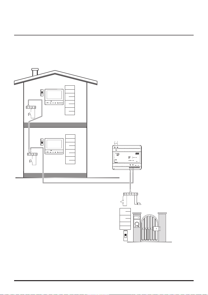
• Nuovo impianto citofonico
Impianto realizzato senza modifiche ai 2 fili
esistenti: chiamata, videocitofono e serratura.
• New door entry system
System made without modifications to the 2 existing
wires; call, video handset and electric door lock.
• Nouvelle installation phonique
Installation réalisée sans modifications sur les 2 fils
existants: appel, vidéophone, et serrure électrique.
• Neue haustelefonanlage
Anlage ohne Änderungen an den vorhandenen 2 Leiter:
Ruffunktion, Gegensprechanlage und elektrisches Schloss.
• Nueva instalación interfónica
Instalación realizada sin las modificaciones a los 2 hilos
existentes: llamada, videoportero y cerradura eléctrica.
• Nieuwe deurtelefooninstallatie
Installatie aangelegd zonder wijzigingen aan de
2 bestaande aders: oproep, beeldhuistelefoon en
elektrisch deurslot.
• Nova instalação do intercomunicador
Instalação realizada sem modificar os 2 fios existentes:
chamada, intercomunicador vídeo e fechadura eléctrica.
• Nowy system wideodomofonowy
Instalacja realizowana bez modyfikacji istniejącego
okablowania (2 przewody) z funkcjami systemu
wideodomofonowego
230 Vac
230 Vac 12 V
*
*Acquistabile separatamente
*Can be purchased separately
*Vendu séparément
*Auf Anfrage getrennt erhältlich
*A la venta por separado
*Apart verkrijgbaar
*Adquirível separadamente
*Dodatkowy aparat zamawiany oddzielnie

4
D
BC
A
>0,2 mm2
BTicino
L4669
0,35 mm20,28 mm2
BTicino
C9881U/5E
AWG24 UTP5
BTicino
336904
One PTT
278 TP
0,28 mm2
OneSYT
+ Digital
TP
5/10
OneSYT
+ Num TP
5/10
GIGA TW
CAT5E
AWG24
One SYT
+ Num TP
8/10
Cable
ARB.6060-1
6/10
Cable
EV6R
6/10
1
mm2
A 50 m 140 m 145 m 200 m 200 m 150 m 200 m 50 m –
B 50 m 115 m 80 m 200 m 115 m 80 m 200 m 50 m –
C 50 m 100 m 65 m 200 m 100 m 65 m 200 m 50 m –
D 30 m 30 m – 50 m 30 m – – – 100 m
• Cavi e distanze (mm2)
• Cables and distances (mm2)
• Câbles et distances (mm2)
• Kabeln und Abstände (mm2)
• Cables y distancias (mm2)
• Kabels en afstanden (mm2)
• Cabos e distâncias (mm2)
• Przekrój przewodu (mm2) a odległość

Video Kit
5
•
Schema monofamiliare
•
One-family diagram
•
Schéma mono-familial
•
Schema Einfamilienhaus
•
Esquema monofamiliar
•
Schema eensgezins
•
Esquema monofamiliar
•
Schemat dla domu jednorodzinnego
B
N=–
=–
T=–
S=–
P=–
–
=
2
1
BUS
PL S+S-
A
ON
OFF
P=–
=–
=–
=–
M
J2
J1
N=–
=–
BUS
230 Vac
•APulsante locale apertura serratura.
BChiamata al piano.
S+ S- 18 V; 4 A impulsivi. 250 mA mantenimento (30 Ω max).
•ADoor lock release local pushbutton.
BFloor call.
S+ S- 18 V; 4 A impulsive. 250 mA holding current (30 Ω max).
•ABouton local ouverture serrure.
BAppel à l’étage.
S+ S- 18 V; 4 A impulsifs. 250 mA entretien (30 Ω max).
•ALokale Schlossöffnungstaste.
BEtagenruf.
S+ S- 18 V; 4 A impulsstrom. 250 mA Haltestrom (30 Ω max).
•APulsador local apertura cerradura.
BLlamada al piso.
S+ S- 18 V; 4 A por impulsos. 250 mA mantenimiento (30 Ω max).
•ALokale knop opening slot.
BOproep aan verdieping.
S+ S- 18 V; 4 A impulsief; 250 mA onderhoud (30 Ω max).
•ABotão local de abertura da fechadura.
BChamada ao piso.
S+ S- 18 V; 4 A instantâneos. 250 mA continuos (30 Ω max).
•ALokalny przycisk otwarcia zamka
BWywołanie z przycisku dzwonka
S+ S- 18V; 4A impuls, 250 mA podtrzymanie (maks. 30 Ω)
1Monofamiliare - One family - Mono-familial - Einfamilienhaus
Monofamiliar - Eengezins - Monofamiliar - Jednorodzinny
2Bifamiliare -Two family - Bi-familial - Zweifamilienhaus
Bifamiliar - Tweegezins - Bifamiliar - Dwurodzinny

6
• Schema bifamiliare 1
• Two-family diagram 1
• Schéma bi-familiale 1
• Schema Zweifamilienhaus 1
• Esquema bifamiliar 1
• Schema tweegezins 1
• Esquema bifamiliar 1
• Schemat dla domu dwurodzinnego - 1
*
BUS
PL S+S-
N=–
=–
T=–
S=–
P=–
–
=
2
1
A
ON
OFF
ON
OFF
BUS
B
BUS
B
P=–
=–
=–
=–
M
J2
J1
N=–
=*1
P=–
=–
=–
=–
M
J2
J1
N=–
=–
230 Vac
* • Il secondo posto interno ed il configuratore 3501/1 devono essere acquistati separatemente.
• The second internal unit and the 3501/1 configurator must be purchased separately.
• Le deuxième poste interne et le configurateur 3501/1 doivent être achetés séparément.
• Die zweite Hausstation und der Konfigurator 3501/1 werden getrennt verkauft.
• La segunda unidad interior y el configurador 3501/1 se han de comprar por separado.
• De tweede binnenpost en de configurator 3501/1 moeten apart worden gekocht.
• A segunda unidade interna e o configurador 3501/1 devem ser adquiridos separadamente.
• Dodatkowy aparat wewnętrzny oraz konfigurator 3501/1 zamawiane oddzielnie.
•APulsante locale apertura serratura.
BChiamata al piano.
S+ S- 18 V; 4 A impulsivi. 250 mA mantenimento (30 Ω max).
•ADoor lock release local pushbutton.
BFloor call.
S+ S- 18 V; 4 A impulsive. 250 mA holding current (30 Ω max).
•ABouton local ouverture serrure.
BAppel à l’étage.
S+ S- 18 V; 4 A impulsifs. 250 mA entretien (30 Ω max).
•ALokale Schlossöffnungstaste.
BEtagenruf.
S+ S- 18 V; 4 A impulsstrom. 250 mA Haltestrom (30 Ω max).
•APulsador local apertura cerradura.
BLlamada al piso.
S+ S- 18 V; 4 A por impulsos. 250 mA mantenimiento (30 Ω max).
•ALokale knop opening slot.
BOproep aan verdieping.
S+ S- 18 V; 4 A impulsief; 250 mA onderhoud (30 Ω max).
•ABotão local de abertura da fechadura.
BChamada ao piso.
S+ S- 18 V; 4 A instantâneos. 250 mA continuos (30 Ω max).
•ALokalny przycisk otwarcia zamka
BWywołanie z przycisku dzwonka
S+ S- 18V; 4A impuls, 250 mA podtrzymanie (maks. 30 Ω)
Nota: è possibile installare un solo Classe300X per ogni rete Wi-Fi (SSID)
Nota: It is possible to install just one Classe300X for each Wi-Fi (SSID) network
Note : il est possible d’installer un seul dispositif Classe 300X pour chaque réseau Wi-Fi (SSID)
Anmerkung: es kann nur ein Gerät Classe 300X für jedes Wi-Fi-Netz (SSID) installiert werden
Nota: se pueden instalar un solo Classe300X por cada redWi-Fi (SSID)
Opmerking: per WiFi-netwerk (SSID) kan slechts één Classe300X worden geïnstalleerd
Nota: é possível instalar apenas um Classe300X para cada rede Wi-Fi (SSID)
Uwaga: dla jednej sieci Wi-Fi (SSID) można zainstalować wyłącznie 1 aparat Classe300X13E
1Monofamiliare - One family - Mono-familial - Einfamilienhaus
Monofamiliar - Eengezins - Monofamiliar - Jednorodzinny
2Bifamiliare -Two family - Bi-familial - Zweifamilienhaus
Bifamiliar - Tweegezins - Bifamiliar - Dwurodzinny

Video Kit
7
230 Vac
BUS
PL S+ S-
N= –
= –
T = –
S = –
P= –
–
=
2
1
A
ON
OFF
ON
OFF
BUS
B
BUS
B
P= –
= –
= –
= –
M
J2
J1
N= –
= *1
P= –
= –
= –
= –
M
J2
J1
N= –
= –
*
• Schema bifamiliare 2
• Two-family diagram 2
• Schéma bi-familiale 2
•
Schema Zweifamilienhaus 2
• Esquema bifamiliar 2
• Schema tweegezins 2
• Esquema bifamiliar 2
• Schemat dla domu dwurodzinnego - 2
* • Il secondo posto interno ed il configuratore 3501/1 devono essere acquistati separatemente.
• The second internal unit and the 3501/1 configurator must be purchased separately.
• Le deuxième poste interne et le configurateur 3501/1 doivent être achetés séparément.
• Die zweite Hausstation und der Konfigurator 3501/1 werden getrennt verkauft.
• La segunda unidad interior y el configurador 3501/1 se han de comprar por separado.
• De tweede binnenpost en de configurator 3501/1 moeten apart worden gekocht.
• A segunda unidade interna e o configurador 3501/1 devem ser adquiridos separadamente.
• Dodatkowy aparat wewnętrzny oraz konfigurator 3501/1 zamawiane oddzielnie.
*
Nota: è possibile installare un solo Classe300X per ogni rete Wi-Fi (SSID)
Nota: It is possible to install just one Classe300X for each Wi-Fi (SSID) network
Note : il est possible d’installer un seul dispositif Classe 300X pour chaque réseau Wi-Fi (SSID)
Anmerkung: es kann nur ein Gerät Classe 300X für jedes Wi-Fi-Netz (SSID) installiert werden
Nota: se pueden instalar un solo Classe300X por cada redWi-Fi (SSID)
Opmerking: per WiFi-netwerk (SSID) kan slechts één Classe300X worden geïnstalleerd
Nota: é possível instalar apenas um Classe300X para cada rede Wi-Fi (SSID)
Uwaga: dla jednej sieci Wi-Fi (SSID) można zainstalować wyłącznie 1 aparat Classe300X13E
1Monofamiliare - One family - Mono-familial - Einfamilienhaus
Monofamiliar - Eengezins - Monofamiliar - Jednorodzinny
2Bifamiliare -Two family - Bi-familial - Zweifamilienhaus
Bifamiliar - Tweegezins - Bifamiliar - Dwurodzinny

8
• Opzione serratura a relè
• Relay door lock option
• Option serrure à relais
• Option Relais-Schloss
• Opción cerradura de relé
• Optie relaisslot
• Opção trinco de relê
• Opcja z przekaźnikiem dla zamka
BUSPL S+S-
N=–
=–
T=–
S=–
P=–
–
=
8 A cosφ = 1
4 A cosφ = 0,7
3 A cosφ = 0,4
24 Vdc; 24 Vac
24 Vac
24 Vac
NO
NC
C
346250 (*)
S- S+ CNC NO
A
* • Fornito a corredo.
• Supplied.
• Fourni.
• Wird mitgeliefert.
• En dotación.
• Standaard meegeleverd.
• Fornecido no equipamento base.
• W zestawie
•APulsante locale apertura serratura.
S+ S- 18 V; 4 A impulsivi. 250 mA mantenimento (30 Ω max).
•ADoor lock release local pushbutton.
S+ S- 18 V; 4 A impulsive. 250 mA holding current (30 Ω max).
•ABouton local ouverture serrure.
S+ S- 18 V; 4 A impulsifs. 250 mA entretien (30 Ω max).
•ALokale Schlossöffnungstaste.
S+ S- 18 V; 4 A impulsstrom. 250 mA Haltestrom (30 Ω max).
•APulsador local apertura cerradura.
S+ S- 18 V; 4 A por impulsos. 250 mA mantenimiento (30 Ω max).
•ALokale knop opening slot.
S+ S- 18 V; 4 A impulsief; 250 mA onderhoud (30 Ω max).
•ABotão local de abertura da fechadura.
S+ S- 18 V; 4 A instantâneos. 250 mA continuos (30 Ω max).
•ALokalny przycisk otwarcia zamka
S+ S- 18V; 4A impuls, 250 mA podtrzymanie (maks. 30 Ω)

Video Kit
9
160 – 165 cm
90 – 130 cm
• Dati dimensionali
• Dimensional data
• Données dimensionnelles
• Maße
• Datos dimensionales
• Formaatgegevens
• Dados dimensionais
• Dane wymiarowe
194 mm
162 mm
25 mm
100 mm
190 mm
26 mm
80°
115 cm 50 cm
105°
140cm
50cm
• Altezza consigliata salvo diversa normativa vigente.
• Recommended height, unless different regulations are specified.
• Hauteur conseillée sauf autre norme en vigueur.
• Empfohlene Höhe falls die gesetzlichen Vorschriften nichts anderes vorschreiben.
• Altura recomendada salvo normativa vigente diferente.
• Aanbevolen hoogte behoudens andere normen in voege.
• Altura aconselhada a não ser se a norma em vigor for diferente.
• Zalecana wysokość montażu o ile inne wymagania lub normy nie stanowią inaczej
• Campo di ripresa
• Field of view
• Éclairage cadrage caméra
• Aufnahmebereich
• Campo de filmación
• Campo de filmagem
• Opnameveld
• Pole widzenia kamery

10
• Posto esterno
• Entrance panel
• Poste extérieur
• Türstation
• Placa exterior
• Externe plaats
• Unidade externa
• Panel zewnętrzny
1
2
3
4
5
4
6
7
16
15
14
12
13
11
10
9
8
1 - Telecamera
2 - LED illuminazione campo di ripresa
3 - Morsetti di collegamento
4 - Pulsanti di chiamata
5 - Posizione antenna lettore badge
6 - LED connessione attiva
7 - LED indicazione porta aperta
8 - Microfono
9 - Regolazione microfono
10 - Regolazione altoparlante
11 - Switch mono/bifamiliare
12 - Pulsante programmazione badge/Reset
13 - Pannello LED per illuminazione pulsante di
chiamata
14 - Sede dei configuratori
15 - Sensore di luminosità per retroilluminazione
notturna
16 - Altoparlante
1 - Caméra
2 - Voyant éclairage champ de cadrage
3 - Bornes de branchement
4 - Boutons d’appel
5 - Position antenne lecteur badge
6 - Voyant connexion active
7 - Voyant indication porte ouverte
8 - Micro
9 - Réglage micro
10 - Réglage haut-parleur
11 - Commutateur mono/bi-familial
12 - Bouton de programmation badge/Reset
13 - Panneau Voyant d’éclairage bouton d’appel
14 - Logement des configurateurs
15 - Capteur de luminosité pour rétro-éclairage
nocturne
16 - Haut-parleur
1 - Camera
2 - Viewing field lighting LED
3 - Connection clamps
4 - Call pushbuttons
5 - Position of the key card reader aerial
6 - Active connection LED
7 - Open door notification LED
8 - Microphone
9 - Microphone adjustment
10 - Loudspeaker adjustment
11 - One-family/two-family switch
12 - Key card programming pushbutton / Reset
13 - LED panel for call pushbutton lighting
14 - Configurator socket
15 - Brightness sensor for night backlighting
16 - Loudspeaker

Video Kit
11
1 - Camera
2 - Led verlichting camerabereik
3 - Aansluitklemmen
4 - Oproepknoppen
5 - Positie antenne badgelezer
6 - LED verbinding geactiveerd
7 - LED aanduiding deur geopend
8 - Microfoon
9 - Regeling microfoon
10 - Regeling luidspreker
11 - Schakelaar een-/tweegezins
12 - Knop badgeprogrammering/reset
13 - LED paneel voor verlichting oproepknop
14 - Plaats van de configuratoren
15 - Lichtsensor voor achtergrondverlichting ‘s nachts
16 - Luidspreker
1 - Kamera
2 - LED oświetlenia pola widzenia kamery
3 - Zaciski przyłączeniowe
4 - Przyciski wywołania
5 - Pozycja anteny czytnika zbliżeniowego
6 - LED sygnalizacji połączenia
7 - LED sygnalizacji otwarcia zamka
8 - Mikrofon
9 - Regulacja mikrofonu
10 - Regulacja głośnika
11 - Mikroprzełącznik trybu jednorodzinny /
dwurodzinny
12 - Przycisk programowania / resetu breloków
13 - Podświetlenie LED dla przycisku wywołania
14 - Gniazda konfiguratorów
15 - Czujnik oświetlenia dla aktywacji podświetlenia
nocnego
16 - Głośnik
1 - Kamera
2 - LED Beleuchtung des Aufnahmefelds
3 - Anschlussklemmen
4 - Ruftasten
5 - Position der Antenne Badge-Lesegerät
6 - LED Verbindung aktiv
7 - LED Anzeige Tür offen
8 - Mikrophon
9 - Einstellung des Mikrophons
10 - Einstellung des Lautsprechers
11 - Switch Ein-/Zweifamilienhaus
12 - Programmierungstaste Badge/Reset
13 - LED-Tafel zur Beleuchtung der Ruftaste
14 - Sitz der Konfiguratoren
15 - Helligkeitssensor zur nächtlichen
Rückbeleuchtung
16 - Lautsprecher
1 - Câmara de vídeo
2 - LED de iluminação do campo de filmagem
3 - Bornes de conexão
4 - Botões de chamada
5 - Posição da antena do leitor de crachá
6 - LED de conexão ativa
7 - LED indicação de porta aberta
8 - Microfone
9 - Regulação do microfone
10 - Regulação do altifalante
11 - Interruptor mono/bifamiliar
12 - Botão de programação do Crachá/Rearme
13 - Painel LED para iluminação do botão de
chamada
14 - Sede dos configuradores
15 - Sensor de luminosidade para retroiluminação
noturna
16 - Altifalante
1 - Telecámara
2 - LED iluminación campo de grabación
3 - Bornes de conexión
4 - Pulsadores de llamada
5 - Posición de la antena del lector credencial
6 - LED conexión activada
7 - LED indicación puerta abierta
8 - Micrófono
9 - Regulación del micrófono
10 - Regulación del altavoz
11 - Switch mono/bifamiliar
12 - Pulsador de programación credencial/Reset
13 - Panel LED para iluminación pulsador de
llamada
14 - Alojamiento de los configuradores
15 - Sensor de luminosidad para retroiluminación
nocturna
16 - Altavoz

12
• Posto interno
1 2 4 5 63 7 8 109
19
18
17
20
121314151612
11
21
24
25
26
26
22
23
27282930

Video Kit
13
L’immagine rappresenta il dispositivo con tutte le funzioni abilitate. Verifica sul manuale installatore come
abilitare le funzioni.
I manuali completi sono disponibili sul sito: www.bticino.com
1 - Display 7”(Touch screen)
2 - Tasto spegnimento
3 - App:
tocca per passare alla pagina informazioni dove è
presente un QR Code che ti permette di scaricare
l’app DOOR ENTRY per interagire con il tuo
dispositivo
4 - Data e ora
5 - Connessione Wi-Fi
6 - Associazione dispositivo/app e inoltro chiamata
abilitato/disabilitato
7 - Esclusione suoneria
8 - Attivazione Studio professionale
9 - Microfono
10 - Attivazione Segreteria
11 - Azioni rapide
12 - Guide tattili per non vedenti
13 - Tasto connessione:
l’accensione del led verde lampeggiante indica
una chiamata in arrivo
l’accensione del led verde fisso indica la
comunicazione in corso
14 - Autoaccensione/Ciclamento:
alla pressione del tasto il LED rosso si accende
15 - Tasto Preferiti:
alla pressione del tasto il LED rosso si accende
(Configurazione base = LUCE SCALE. Per una
diversa configurazione fare riferimento alla tabella
della configurazione fisica alle pagine successive.)
16 - Tasto apertura serratura:
alla pressione del tasto il LED rosso si accende
17 - Stato Wi-Fi:
Led rosso lampeggiante = Wi-Fi attivo ma non
connesso ad una rete
Led spento = Wi-Fi disabilitato o correttamente
funzionante
Led verde fisso = il Classe 300X sta scambiando
dati con l’app DOOR ENTRY
(inoltro chiamata, autoaccensione)
Nota: Nel momento in cui l’app DOOR ENTRY è
collegata con l’impianto (es. rispondere ad una
chiamata, visualizzare un Posto Esterno, ecc.), non si
possono eseguire altre operazioni ad eccezione del
tasto apertura serratura e Tasto Preferiti (configurato
per la funzione Luci Scale o Comando Diretto Serratura )
che continuano a funzionare
18 - Stato presenza note:
Led rosso lampeggiante = nuova/e note non lette
o messaggio/i in segreteria
19 - Stato Esclusione suoneria:
Led rosso acceso = Suoneria chiamata disattivata
20 - Funzioni (compaiono solo le icone delle funzioni
configurate)
21 - Sede dei configuratori (vedi“Funzioni
configuratori”)
22 - Configuratore J1: estrai se è presente
l’alimentazione supplementare (morsetto 1 & 2)
23 - Configuratore J2: per il corretto funzionamento
non estrarre
24 - Microinterruttore ON/OFF di terminazione di
tratta
25 - Presa mini USB per aggiornamento Firmware
dispositivo
26 - Altoparlante
27 - Morsetti (1 - 2) per alimentazione supplementare
28 - Morsetti per il collegamento al BUS SCS 2 FILI
29 - Morsetti ( ) per il collegamento di un pulsante
esterno di chiamata al piano
30 - Morsetti (1 - 5M) per il collegamento di una
suoneria supplementare. Devi effettuare il
collegamento punto - punto sui morsetti delle
suonerie supplementari

14
• Video Internal unit
1 2 4 5 63 7 8 109
19
18
17
20
121314151612
11
21
24
25
26
26
22
23
27282930

Video Kit
15
The image shows the device with all its functions enabled. Check on the Installer Manual how to enable the functions.
The complete manuals are available on the website: www.bticino.com
1 - 7” (Touch screen) display
2 - OFF key
3 - App:
touch to display the information page where you
find a QR code that allows the download of the
DOOR ENTRY app to interact with your device
4 - Date and time
5 - Wi-Fi Connection
6 - Device/app association and enabled/disabled
forwarding of call
7 - Bell exclusion
8 - Office activation
9 - Microphone
10 - Answering machine activation
11 - Quick actions
12 - Tactile guides for the blinds
13 - Connection key:
The green LED flashes to indicate an incoming call
The green LED comes on steady to indicate that there
is an active call
14 - Auto-switching on/Cycling:
The red LED turns on when the key is pressed
15 - Favorites Key:
The red LED turns on when the key is pressed
(Basic configuration = STAIRCASE LIGHT. For
a different configuration refer to the physical
configuration table in the following pages.)
16 - Door lock release key:
The red LED turns on when the key is pressed
17 - Wi-Fi Status:
Red LED flashing = Wi-Fi is active but not connected
to a network
LED off = disabled or properly functioning Wi-Fi
Green LED fixed = the Classe 300X is exchanging
data with the DOOR ENTRY app
(forwarding of call, auto-switching on,
configuration)
18 - Message status:
Red LED flashing = new unread note/s or message/s
in the answering machine
19 - Bell exclusion Status:
Red LED on = Call bell disabled
20 - Functions (only the icons for the configured
functions are displayed)
21 - Configurator seat (See “Configurator Functions”)
22 - Configurator J1: remove if the additional power
supply is present (clamp 1 and 2)
23 - J2 configurator: for correct operation do not remove
24 - Line termination ON/OFF micro-switch
25 - Mini USB socket for device Firmware update
26 - Loudspeaker
27 - Additional power supply clamps (1 - 2)
28 - 2 WIRE SCS/BUS connection clamps
29 - Clamps ( ) for the connection of an external call
to the floor pushbutton
30 - Additional bell connection clamps (1 - 5M) Point-to-
Point connections are required on the clamps of the
additional bells
Note: When the DOOR ENTRY is connected to the
system (e.g. answer a call, display an Entrance Panel,
etc.), no operations can be made, with the exception of
the door lock release key and Favorite Key (configured
for the Staircase Light or Door Lock Direct Control
functions) that continue to operate.

16
• Poste interne
1 2 4 5 63 7 8 109
19
18
17
20
121314151612
11
21
24
25
26
26
22
23
27282930

Video Kit
17
L’image représente le dispositif avec toutes les fonctions activées.
Vérifier dans le Manuel Installateur le mode d’activation des fonctions.
Les manuels complets sont disponibles sur le site: www.bticino.com
1 -
Écran 7” (Écran Tactile
2 -
Touche d’extinction
3 -
Application :
toucher pour passer à la page des informations où
est présent un code QR qui permet de télécharger
l’application DOOR ENTRY pour interagir avec le
dispositif
4 -
Date et heure
5 -
Connexion Wi-Fi
6 -
Association dispositif/application et envoi d’appel
activé/désactivé
7 -
Exclusion sonneries
8 -
Activation Bureau
9 -
Micro
10 -
Activation Répondeur
11 -
Actions rapides
12 -
Guides tactiles pour non-voyants
13 -
Touche connexion :
l’allumage du voyant vert clignotant indique la
présence d’un appel entrant
l’allumage du voyant vert fixe indique la
communication en cours
14 -
Auto-allumage/Cyclage :
à la pression sur la touche le VOYANT rouge s’allume
15 -
Touche Favoris :
à la pression sur la touche le VOYANT rouge s’allume
(Configuration de base = LUMIÈRE ESCALIER. Pour
une configuration différente, faire référence au
tableau de la configuration physique dans les pages
suivantes.)
16 -
Touche d’ouverture serrure:
à la pression sur la touche le VOYANT rouge s’allume
17 -
État Wi-Fi :
Voyant rouge clignotant = Wi-Fi activé mais non
connecté à un réseau
Voyant éteint = Wi-Fi désactivé ou fonctionnant
correctement
Voyant vert fixe = le dispositif Classe 300X échange
des données avec l’application DOOR ENTRY (envoi
d’appel, auto-allumage ou configuration).
18 -
État présence notes :
Voyant rouge clignotant = nouvelle(s) note(s) non
lue(s) ou message(s) sur le répondeur
19 -
État Exclusion sonnerie:
Voyant rouge allumé = Sonnerie appel désactivée
20 -
Fonctions (seules les icônes des fonctions
configurées s’affichent)
21 -
Logement configurateurs (voir “Fonctions
configurateurs”)
22 -
extraire en présence de l’alimentation
supplémentaire (bornes 1 et 2)
23 -
Configurateur J2: pour le bon fonctionnement ne
pas extraire
24 -
Microinterrupteur ON/OFF de terminaison de ligne
25 -
Prise miniUSB de mise à jour Firmware dispositif
26 -
Haut-parleur
27 -
Bornes (1 – 2) d’alimentation supplémentaire
28 -
Bornes de branchement au BUS SCS 2 FILS
29 -
Bornes ( ) de branchement d’un bouton externe
d’appel à l’étage
30 -
Bornes (1 - 5M) de branchement d’une sonnerie
supplémentaire Le branchement doit être
effectué point - point sur les bornes des sonneries
supplémentaires
Note : Au moment où l’application DOOR ENTRY est
connectée à l’installation (ex. réponse à un appel,
visualisation d’un poste externe, etc.), aucune autre
opération ne peut être effectuée, seules la touche
d’ouverture serrure et la touche des favoris (configurée
pour la fonction Lumière escaliers ou Commande
directe serrure) continuent de fonctionner.

18
1 2 4 5 63 7 8 109
19
18
17
20
121314151612
11
21
24
25
26
26
22
23
27282930
• Hausstation

Video Kit
19
Das Bild stellt eine Vorrichtung mit allen aktivierten Funktionen dar.
Sehen Sie im Installationshandbuch nach, wie die Funktionen aktiviert werden.
Die vollständigen Handbücher können von dieser Webseite herunter geladen werden: www.bticino.com
1 -
Display 7” (Touchscreen)
2 -
Ausschalttaste
3 -
App:
Berühren, um die Informationsseite abzurufen,
in der ein QR Code enthalten ist, mit dem die App
DOOR ENTRY heruntergeladen werden kann, die der
Steuerung der Vorrichtung dient.
4 -
Datum und Uhrzeit
5 -
Wi-Fi-Anschluss
6 -
Verbindung Vorrichtung/App und senden eines Rufs
aktivieren/deaktivieren
7 -
Ausschluss des Läutwerks
8 -
Freigabe Büro-Funktion
9 -
Mikrofon
10 -
Freigabe Anrufbeantworter
11 -
Schnellfunktionen
12 -
Taktile Hilfe für Sehbehinderte
13 -
Anschlusstaste:
Das Blinken der grünen Led meldet einen eintreffenden
Anruf
Das Aufleuchten der grünen Led meldet Gespräch im
Gang
14 -
Selbstschaltung/Taktierung:
Durch Drücken der Taste, leuchtet die rote LED auf
15 -
Taste Favoriten:
Durch Drücken der Taste, leuchtet die rote LED auf
(Basis-Konfiguration = TREPPENLICHT. Um die
Konfiguration zu ändern, siehe Tabelle der physischen
Konfiguration auf der nachfolgenden Seite.)
16 -
Taste Schlossöffner:
Durch Drücken der Taste, leuchtet die rote LED auf
17 -
Wi-Fi-Status:
Rot blinkende Led = Wi-Fi aktiv aber nicht mit einem
Netz verbunden
Led aus = Wi-Fi deaktiviert oder defekter Betrieb
Grüne LED fest leuchtend = das Gerät Classe 300X
tauscht Daten mit der App DOOR ENTRY aus (Ruf
senden, automatisches Einschalten, Konfiguration)
18 -
Status Nachrichten vorhanden:
Rote Led blinkt = neue nicht gelesene Meldung/en oder
Meldung/en im Anrufbeantworter
19 -
Ausschluss-Status des Läutwerks:
Rote Led leuchtet = Anrufklingel deaktiviert
20 -
Funktionen (es werden nur die Symbole der
konfigurierten Funktionen angezeigt)
21 -
Sitz der Konfiguratoren (Siehe „Funktion der
Konfiguratoren“)
22 -
Konfigurator J1: abziehen, wenn ein zusätzliche
Stromversorgung vorhanden ist (Klemme 1 & 2)
23 -
Konfigurator J2: für einen einwandfreien Betrieb nicht
heraus nehmen
24 -
Mikroschalter ON/OFF fur den Streckenabschluss
25 -
Mini-USB-Steckbuchse zur Aktualisierung der Firmware
der Vorrichtung
26 -
Lautsprecher
27 -
Klemmen (1 -2) für eine zusätzliche Stromversorgung
28 -
Klemmen zum Anschluss an BUS, SCS, 2-DRAHT
29 -
Klemmen ( ) zum Anschluss an eine externe
Etagenruftaste
30 -
Klemmen (1 - 5M) zum Anschluss an ein zusätzliches
Läutwerk Der Anschluss muss Punkt zu Punkt an den
Klemmen des zusätzlichen Läutwerks erfolgen
Anmerkung: Wenn die App DOOR ENTRY mit der
Anlage verbunden ist (z.B. einen Ruf beantworten,
eine Türstation anzeigen usw.), können keine
Funktionen außer die Tasten Türöffner und Favoriten
(für Treppenlicht oder direkte Schlosssteuerung
konfiguriert) verwendet werden.

20
• Unidad interior
1 2 4 5 63 7 8 109
19
18
17
20
121314151612
11
21
24
25
26
26
22
23
27282930
Table of contents
Other Bticino Telephone manuals

Bticino
Bticino 365711 User manual

Bticino
Bticino 344612 User manual

Bticino
Bticino Classe 300X User manual

Bticino
Bticino Terraneo 335022 User manual

Bticino
Bticino Classe 300X User manual

Bticino
Bticino BTI-366511 User manual

Bticino
Bticino 344682 User manual

Bticino
Bticino Classe 300X User manual

Bticino
Bticino 323001 User manual