Securing the Tail of the Lifeline to the Ladder:
1. Pull the slack out of the lifeline (pulling away from anchor), and form a loop in the lifeline in front of the 2nd or 3rd rung (on the
bottom) of the ladder (Fig. 7).
2. Wrap the loop behind the rung (Fig. 8).
3. Bring loop around behind the doubled lifeline and back through the doubled loop formed (Fig. 9 –10).
4. Pull knot tight (Fig. 11).
Note: Securing the lifeline to the ladder allows for the user to remove slack from the lifeline
Attaching MFA to Harness:
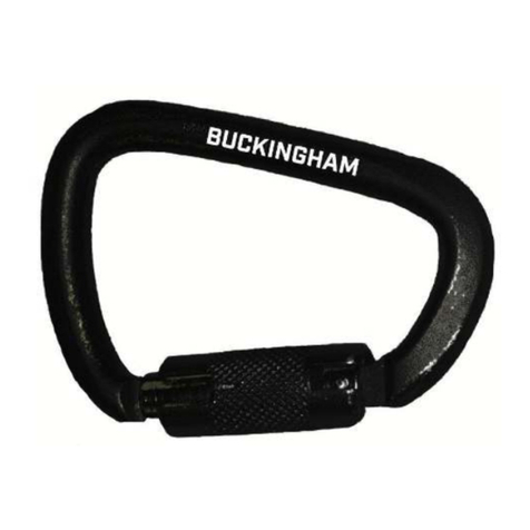
1. Open the Integral Attachment Carabiner gate (Fig. 12).
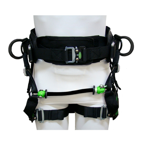
2. Connect the carabiner to the Harness Sternal D-ring (Fig. 13).
3. Ensure the carabiner gate is completely closed (Fig. 14).
Inspect Prior to Each Use
Inspection should include but not be limited to the following:
•BuckArrester MFA is free of cracks –(usually depicted by fine jagged lines) and extensive wear or corrosion to the cam or
housing.
•Cam is properly installed into the frame and facing the correct direction (as shown in the sketch on the frame) (Fig. 15).
•Shoulder Bolt and locking nut are in place and securely tightened.
•Inspect rope (lifeline installed on ladder) to ensure no excessive wear, burns, cuts, abrasions, kinks, knots, ice buildup, or any
broken strands in any given area of rope exist. Additionally, the core of the rope is of a contrasting color from the cover to aid in
inspection.
•BuckArrester MFA is properly installed onto the lifeline with the UP Arrow facing the anchor, or top of the ladder.
•Proper operation of the BuckArrester MFA by pivoting the cam lever back and forth. Movement should be unrestricted with no
binding resulting from debris, packed snow, or ice, etc.
•Proper movement of the BuckArrester MFA up and down the rope.
•Carabiner gate is not cracked or bent, is free of burrs, clean, and functioning properly.
•Impact load indicator is intact and not deployed. The impact load indicator is located in the integral lanyard inside of the
carabiner eye (Fig. 16 - 17). It consists of a fold in the webbing that is stitched such that when a force in excess of 600 lb. is
applied to the unit, the thread breaks causing the indicator to deploy resulting in the length of the eye to increase indicating the
unit has been subjected to an impact (Fig. 18 - 19).
5004BQ2 BuckArrester_112917 (Rev. 11/08/18) 2 of 4
PN 230425
