manuals.online logo
Brands
  1. Home
  2. •
  3. Brands
  4. •
  5. Buckingham
  6. •
  7. Security Sensor
  8. •
  9. Buckingham BuckAdjuster User manual

Buckingham BuckAdjuster User manual

Fig. 3c
BUCKINGHAM MFG.
Adjustable Positioning Lanyard Instructions / Warnings
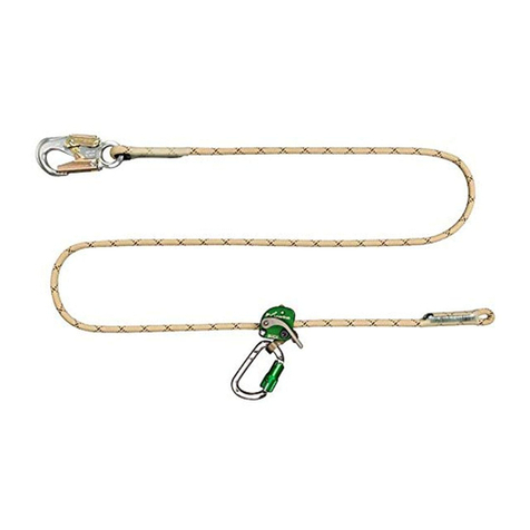
“BuckAdjuster” 1/2” 16 strand braided rope. Manufacturing matrix material option “8K” (see Fig.1)
“RigidLine” 7/16” parallel core cable
of polyester filament. Manufacturing
matrix material option “8R” (see Fig.2)
Inspect Prior to each use: inspection
should include but not be limited to the
following:
Rope Inspection:
Inspecting your rope should be a continuous process of observation
before, during, and after each use.
Inspect rope fibers for signs of excessive wear, burns, cuts,
abrasions, kinks, knots, hockling, ice buildup, broken strands in any
given area of the rope.
If ice or snow build-up is noted, remove build-up prior to use by
running the length adjusting device along the length of the rope. Ensure
the length adjusting device is clean and free of packed
snow or ice.
Both outer and inner fibers contribute to the ropes strength. If either is
worn, the rope will naturally be weakened. Open the rope strands and
look for powdered fiber, which is one sign of internal rope wear.
Inspect the rope for frayed strands and broken yarns. Check for pulled strands. A pulled strand
should be re-threaded into the rope if possible, otherwise it may snag on a foreign object during
use.
Inconsistent texture or stiff areas can indicate excessive dirt or grit embedded in the rope or shock
load damage. Check that rope has not become hard or compacted. A hard or compacted rope
indicates reduced strength.
Inconsistent diameter (flat areas, bumps, or lumps). This condition indicates core or internal
damage from overloading or shock loading.
With use, all ropes become dirty. Inspect for areas of discoloration that could have been caused by
chemical contamination and may result in the rope becoming brittle or stiff.
Glossy or glazed areas that generally indicate signs of heat damage.
Rope, rope stitching, splice or rope crimp and all whipped ends are free of defects
(see Fig. 3a, 3b & 3c). Stitched eyes must have a protective cover (shrink tube) over the stitching
and the cover must not be damaged, missing or torn. (see Fig. 3b ).
Terminations of RigidLine extends through crimp. The crimp is secure and tight.
If your Adjustable Positioning Lanyard is manufactured using Matrix Rope Option “8K” or “8R”
do not use rope that has the red warning center / core exposed.
See photos below for examples of a variety of conditions indicated above:
Hockled Rope Rope with a Pulled Strand Rope with Broken or Cut Strands
Fig. 1
Fig. 3a
Fig. 3b
MODEL 9-8 shown in Fig. 1.
Other models may have varying lengths, options
& hardware from figures shown.
MODEL 7V08R18GM6 shown in Fig. 2.
Other models may have varying lengths, options
& hardware from figures shown.
Fig. 2
BuckAdjuster.Doc
P/N 230194 Rev. 3-7-17
1/4
Melted / Glossy or Glazed Strands Rope with Excessive Abrasion Wear RigidLine with Excessive Abrasion Wear
(Red Warning core showing)
Snap Hook / Carabiner Inspection:
Ensure locking device and keeper / gate operate freely and smoothly and that keeper / gate closes and remains closed and locked until
intentionally opened.
Inspect to ensure component is free of cracks, distortion, corrosion, or nicks.
Ensure keeper / gate is not bent, is free of burrs, not packed with snow or ice, and that snap hooks / carabiners are clean and
functioning properly.
Length Adjusting Device (LAD) Inspection:
Unit is free of cracks –(usually depicted by fine jagged lines) and extensive wear or corrosion to cam lever, housing, or cam
lever eye.
The spring is assembled into the cam lever and body correctly.
Ensure that the cam lever is installed in the proper orientation to the body (cam lever must be mounted in the same direction as
shown in the sketch on the side of Length Adjusting Device (LAD)).
Ensure that the centerlock nut is securely attached to the shoulder bolt. The bolt should be above or flush with the surface of the nut.
Proper operation of mechanism by pivoting cam lever back and forth. Movement should be unrestricted with no binding.
Binding could be caused by burrs, packed snow, or ice. A burr can be removed by disassembling the Length Adjusting Device
(LAD) and lightly sanding the burr down with fine grit emery cloth.
NOTE: Also read and follow other instructions, warnings, and inspection guidelines enclosed with this product.
If any evidence of wear or deterioration as outlined above is observed, immediately cease use, destroy the product, and replace it with
new equipment. Should any unusual conditions not outlined above be observed, or you have reasonable doubt about a particular
condition, remove the equipment from service and notify your Supervisor, Safety Director, or contact Buckingham Mfg. Co. for
clarification. Failure to carefully and completely inspect your equipment could result in serious injury or death.
Warnings:
Know the job and the regulations governing performance requirements and select the proper equipment.
Read carefully, understand, and heed these and all other included instructions, warnings, and cautions before using this equipment.
Failure to do so could result in your serious injury or death. Should questions arise concerning the proper use or condition of your
equipment, contact Buckingham Manufacturing Co. at 1-800-937-2825.
All affixed labels should be left in place and all instructional material kept for future reference.
This equipment is intended for use by properly trained professionals only.
This product is designed to be used by a person with a maximum weight of 350 lbs. when fully equipped.
For personal use only. NOT for towing or hoisting.
Fall protection equipment, (i.e. fall arrest, work positioning belts, climbers, retrieval, suspension etc.) should not be resold or
provided to others for re-use after use by original user as assurance cannot be granted that a used product meets criteria of applicable
standards and is safe for use to a subsequent user.
Be certain this equipment is suitable for the intended use and work environment. It should only be used as personal protection
equipment (PPE). If suitability for intended use is in doubt, consult a safety engineer or contact Buckingham Mfg. before using.
Destroy any and all equipment subjected to impact loading.
Always attach each snap hook of the positioning strap to the proper circle D-ring of the body belt.
Do not attach work positioning snap hooks to accessory rings. Accessory rings are intended for attachment of a belt supporter only.
Note: Belt supporters are intended to distribute belt weight of users who carry an unusually heavy load of tools. Belt supporters are
not intended to support the weight of the user.
As outlined by OSHA 1926.502 (e)(2) positioning devices shall be secured to an anchorage capable of supporting at least twice the
potential impact load of an employee's fall or 3,000 lbf. (13.3 kN), whichever is greater.
Manufactured to the following standards / regulations as they are applicable ASTM F887 / ANSI Z359.3 / OSHA 1926.959 /
CA. OSHA 2940.6.
The Adjustable Positioning Lanyard is only one component / element of a positioning system outlined by ASTM F887 / ANSI Z359.3.
Avoid contact of this equipment with sharp edged or pointed tools, high temperature surfaces, welding or other heat sources.
(Be aware of the lanyards position / placement on the pole or tree at all times in relation to the operations being performed. Use
extreme caution when performing operations such as cutting, drilling, sawing, etc. Always perform this type of work well above the
lanyard to avoid the potential of tool contact with the lanyard, causing damage which may result in a fall, serious injury or death).
BuckAdjuster.Doc
P/N 230194 Rev. 3-7-17
2/4
Fig. 9
Fig. 8
Guard against debris which could block the action of the cam (pebbles, twigs, ice, snow, etc.).
If ice or snow buildup is noted, run the adjusting device along the length of the rope to remove the build-up and ensure the adjusting
device is clean and free of packed snow or ice.
Only Buckingham Mfg. Co., or those authorized in writing by Buckingham Mfg. Co., may make repairs / modifications to this
equipment.
Remove from service if subjected to impact loading. Even though no visible signs are present, internal damage may have occurred
thus reducing its strength and margin of safety.
This product is intended for work positioning only.
The arrow on the housing should always point away from the user & towards the attached locking snaphook. Note: - Improper
orientation of the LAD will result in the loss of locking action required to maintain adjustment of the rope when in use.
The cam lever must be installed in the body in the same direction as shown in the sketch on the LAD body. Note: - Improper
orientation of the cam lever will result in the loss of locking action required to maintain adjustment of the rope when in use.
Center lock nut is not to be re-used after initial loosening or removal.
LAD shall not be used on steel cable or wire rope.
In the event of a cutout and if the cam lever of the LAD is held in the open position, rope will continue to feed through unit.
Therefore, cam lever must be released for rope to stop feeding through LAD.
Never wrap an Adjustable Positioning Lanyard around a sharp member as the material could be cut or damaged.
Units manufactured with Anti Wear Tubing intended to minimize wear (i.e. abrasion, cuts, etc.) to the rope is intended for use on
poles, trees, and other structures. When used for this function, ensure Anti Wear Tubing is adjusted properly to cover all contact
points of pole, tree, or structure.
With each use, visually check that the Adjustable Positioning Lanyard snap hook / carabiner freely engages the body belt circle D-
ring and that the keeper / gate is completely closed and facing outward. Never rely solely on the feel or sound of a snap hook /
carabiner engaging.
Make sure each snap hook / carabiner is positioned so that its keeper / gate is never load bearing.
When in the work position, ensure there is no pressure on the snap hook locking mechanism sufficient to depress it as this will, due to
its length, render it incompatible with currently designed D-rings and make it very susceptible to rollout.
Lubricate lock mechanism and keeper on both sides of snap hook at least weekly or as often as required to maintain smooth operation
(no binding) with light weight lubricant such as WD-40®.
Product covered under these instructions / warnings should not be resold / redistributed or re-used after use by original user.
Disconnecting / Reconnecting Length Adjusting Device (LAD) onto Rope: This section applies only in the event the
Adjustable Positioning Lanyard (rope line which includes locking snaphook and stitched or spliced eye) is replaced or LAD requires
cleaning or the removal of a burr. Otherwise LAD is not to be disassembled. (See Fig. 4 for LAD part description). Notes: Only use LAD
on compatible and proper diameter ropes which are stated on the side of LAD (see Fig.5). Buckingham LADs have been tested and
approved for use as a Length Adjusting Devices used in conjunction with an Adjustable Positioning Lanyard on the following types of
ropes: M4 LAD (Green) [PN 221027] is designed for ½” rope only and is compatible with the following ropes: ½” Blue Streak 16 strand
rope, ½” XTC 16 strand rope, ½” Kernmantle rope and ½” High Vee rope. The M6 LAD (Blue) [PN 221029] is designed to be used with
7/16” RigidLine only.
To Disconnect / Disassemble:
1. Remove the centerlock nut from the shoulder bolt using a 3/16” Allen
wrench and a 1/2” box end wrench (Fig. 6 & 7).
2. Discard the centerlock nut. Do not re-use.
3. Remove the shoulder bolt by pulling it out through the cam and the body of
the LAD (Fig.8). Discard the bolt. Do not re-use.
4. Remove the cam lever from the body being cautious not to lose the return
spring assembled into it. (Fig.9). Remove the rope from the LAD.
To Connect / Assemble:
Note- Reassembly requires the use of PN 5004BKIT (Nut & Bolt Kit).
1. Insert the rope into the groove of the LAD. The arrow shown on the
device (Fig. 10) must point to the locking snap hook / carabiner end of
the Adjustable Positioning Lanyard. If the Adjustable Positioning Lanyard
is mounted on a pole, tree, or other structure, the arrow must point towards the same.
2. Place the spring into the cam spring slot. The bent tab portion of the spring must point outward, away from the cam (Fig.11).
Fig. 7
Fig. 10
Fig. 11
BuckAdjuster.Doc
P/N 230194 Rev. 3-7-17
3/4
Fig. 4
Fig. 5
Fig. 6
Patent Pending
3. Insert the cam lever and spring back into the body of the LAD (on top of the rope). The spring tab must be started into the small
hole in the side of the LAD body first and then rotated inward (Fig.12).
4. Align the holes of the cam lever and the body of the LAD by pushing the cam lever in the
directions shown (Fig.13 & 14). The cam lever must be mounted in the same direction as shown
in the sketch on the side of the LAD.
5. From either side of the body, insert the new shoulder bolt from PN 5004BKIT completely through
the body and the cam lever (Fig.15).
6. Thread the new centerlock nut from PN 5004BKIT onto the shoulder bolt and tighten until snug
(75 in. lbs. max.) with a 3/16” Allen wrench and a 1/2” box end wrench. Do not over tighten the
nut. The bolt should slightly protrude or be flush with the surface of the nut. (Fig.16).
7. Check by pulling on the eye of the cam lever that the device grips the rope in the required direction.
Be sure to perform a trial test while standing on the ground to ensure the LAD properly grips the rope / locks prior to climbing.
Adjustable Positioning Lanyard Attachment: (options & hardware may vary from product shown below)
Proper Attachment Examples of Improper Attachment
Proper Attachment: Carabiner and locking snaphook must be attached to work positioning D-rings as shown in Fig. 17.
Gates of the carabiner and locking snaphook must be facing out.
Examples of Improper Attachment: Do not connect locking snaphook to anchor point other than work positioning D-rings.
See Fig. 18a & 18b. Do not connect Adjustable Positioning Lanyard back onto itself and use as a cinch or choking device. See Fig.19.
To Operate:
1. Ensure Adjustable Positioning Lanyard is properly attached
by leaning back slowly. Unit should support user.
2. To shorten the Adjustable Positioning Lanyard, lean slightly into
the pole, tree, or other structure while pulling the free end of the
rope through the cam lever and towards the same (Fig.20).
3. To lengthen the Adjustable Positioning Lanyard, slightly lean into
the pole, tree, or other structure, to relax tension on the cam lever,
slowly depress the cam lever towards the pole, tree, or other
structure while leaning back slowly. (Fig.21).
4. While climbing above or below obstructions adjust Adjustable Positioning Lanyard to minimize fall distance to under two feet (2’).
Cleaning / Storage Instructions:
A dirty product should be washed and rinsed in clean water, then dried. Do not store near solvents or corrosive chemicals or at extreme
temperatures. Inspect your equipment carefully before use. This product should be stored in a clean and dry environment out of direct
sunlight and away from extreme climate conditions. Ropes should be stored on racks or hooks to provide ventilation and should never be
stored on concrete or dirt surfaces.
BUCKINGHAM MFG. CO.
1-800-937-2825
E-mail –sales @buckinghammfg.com
Web site –www.buckinghammfg.com
Information contained in these written instructions supersedes all other information (written, audio, video etc.) produced by Buckingham Mfg. prior to the revision date of
this document.
Fig. 13
Fig. 14
Fig. 12
Rotate
Spring
Hole
Fig. 16
Fig.19
Fig.18b
Fig.18a
Fig.17
BuckAdjuster.Doc
P/N 230194 Rev. 3-7-17
4/4
Fig. 21
Fig. 20
Fig. 15

This manual suits for next models

1

Other Buckingham Security Sensor manuals

Buckingham 60007 User manual

Buckingham

Buckingham 60007 User manual

Buckingham BuckTooth 485 User manual

Buckingham

Buckingham BuckTooth 485 User manual

Buckingham 20192CM Guide

Buckingham

Buckingham 20192CM Guide

Buckingham 2139 User manual

Buckingham

Buckingham 2139 User manual

Buckingham 600071 User manual

Buckingham

Buckingham 600071 User manual

Buckingham 101SR Product manual

Buckingham

Buckingham 101SR Product manual

Buckingham 5005TC User manual

Buckingham

Buckingham 5005TC User manual

Buckingham 21402 User manual

Buckingham

Buckingham 21402 User manual

Buckingham RFPDELUXE User manual

Buckingham

Buckingham RFPDELUXE User manual

Buckingham Buck LeverJust 9M8 Series User manual

Buckingham

Buckingham Buck LeverJust 9M8 Series User manual

Buckingham BuckCat Series Product manual

Buckingham

Buckingham BuckCat Series Product manual

Buckingham 4812 Series Product manual

Buckingham

Buckingham 4812 Series Product manual

Buckingham 17904 Product manual

Buckingham

Buckingham 17904 Product manual

Buckingham 5005S5 User manual

Buckingham

Buckingham 5005S5 User manual

Buckingham 3111 User manual

Buckingham

Buckingham 3111 User manual

Buckingham 6263 Series User manual

Buckingham

Buckingham 6263 Series User manual

Buckingham BuckWheel 487 User manual

Buckingham

Buckingham BuckWheel 487 User manual

Buckingham ERGOVATION Series User manual

Buckingham

Buckingham ERGOVATION Series User manual

Buckingham Buck Hook Product manual

Buckingham

Buckingham Buck Hook Product manual

Buckingham K9RETRO User manual

Buckingham

Buckingham K9RETRO User manual

Buckingham 102SR Series Product manual

Buckingham

Buckingham 102SR Series Product manual

Buckingham BuckSkinner User manual

Buckingham

Buckingham BuckSkinner User manual

Buckingham 5004BQ2 User manual

Buckingham

Buckingham 5004BQ2 User manual

Buckingham 574 User manual

Buckingham

Buckingham 574 User manual

Popular Security Sensor manuals by other brands

IntelliSense AWARE installation guide

IntelliSense

IntelliSense AWARE installation guide

Satel AGD-100-BR user manual

Satel

Satel AGD-100-BR user manual

BFT SIBOX instructions

BFT

BFT SIBOX instructions

GEV ATHLET 16873 manual

GEV

GEV ATHLET 16873 manual

Kistler 2629DK instruction manual

Kistler

Kistler 2629DK instruction manual

Xylem OI Analytical 5383 Quick reference guide

Xylem

Xylem OI Analytical 5383 Quick reference guide

ratiotec Soldi Smart Pro USD instruction manual

ratiotec

ratiotec Soldi Smart Pro USD instruction manual

THORLABS PDA10CS user guide

THORLABS

THORLABS PDA10CS user guide

Besantek BST-CBF01 instruction manual

Besantek

Besantek BST-CBF01 instruction manual

MGC MIX-4030 Installation and maintenance instructions

MGC

MGC MIX-4030 Installation and maintenance instructions

THORLABS SPDMA Operation manual

THORLABS

THORLABS SPDMA Operation manual

Varian 990 CLD Autoline instruction manual

Varian

Varian 990 CLD Autoline instruction manual

hager TCC520E Setting instructions

hager

hager TCC520E Setting instructions

GEV LBU 1237 manual

GEV

GEV LBU 1237 manual

HWM PCorr+ manual

HWM

HWM PCorr+ manual

Ferno XT User and maintenance manual

Ferno

Ferno XT User and maintenance manual

BEA IXIO-DT1 manual

BEA

BEA IXIO-DT1 manual

NookBox IRD-23 installation guide

NookBox

NookBox IRD-23 installation guide

manuals.online logo
manuals.online logoBrands
  • About & Mission
  • Contact us
  • Privacy Policy
  • Terms and Conditions

Copyright 2025 Manuals.Online. All Rights Reserved.